D. A.
Sheppard
*a,
C.
Corgnale
b,
B.
Hardy
b,
T.
Motyka
b,
R.
Zidan
b,
M.
Paskevicius
a and
C. E.
Buckley
a
aHydrogen Storage Research Group, Fuels and Energy Technology Institute, Department of Imaging and Applied Physics, Curtin University, GPO Box U1987, Perth, WA 6845, Australia. E-mail: drew.sheppard@gmail.com
bSavannah River National Laboratory, 999-2W, Aiken, SC 29808, USA
First published on 4th June 2014
A simplified techno-economic model has been used as a screening tool to explore the factors that have the largest impact on the costs of using metal hydrides for concentrating solar thermal storage. The installed costs of a number of paired metal hydride concentrating solar thermal storage systems were assessed. These comprised of magnesium-based (MgH2, Mg2FeH6, NaMgH3, NaMgH2F) high-temperature metal hydrides (HTMH) for solar thermal storage and Ti1.2Mn1.8H3.0 as the low-temperature metal hydride (LTMH) for hydrogen storage. A factored method approach was used for a 200 MWel power plant operating at a plant capacity factor (PCF) of 50% with 7 hours of thermal storage capacity at full-load. In addition, the hydrogen desorption properties of NaMgH2F have been measured for the first time. It has a practical hydrogen capacity of 2.5 wt% (2.95 wt% theoretical) and desorbs hydrogen in a single-step process above 478 °C and in a two-step process below 478 °C. In both cases the final decomposition products are NaMgF3, Na and Mg. Only the single-step desorption is suitable for concentrating solar thermal storage applications and has an enthalpy of 96.8 kJ mol−1 H2 at the midpoint of the hydrogen desorption plateau. The techno-economic model showed that the cost of the LTMH, Ti1.2Mn1.8H3.0, is the most significant component of the system and that its cost can be reduced by increasing the operating temperature and enthalpy of hydrogen absorption in the HTMH that, in turn, reduces the quantity of hydrogen required in the system for an equivalent electrical output. The result is that, despite the fact that the theoretical thermal storage capacity of NaMgH2F (1416 kJ kg−1) is substantially lower than the theoretical values for MgH2 (2814 kJ kg−1), Mg2FeH6 (2090 kJ kg−1) and NaMgH3 (1721 kJ kg−1), its higher enthalpy and operating temperature leads to the lowest installed cost of the systems considered. A further decrease in cost could be achieved by utilizing metal hydrides with yet higher enthalpies and operating temperatures or by finding a lower cost option for the LTMH.
The three main methods of thermal energy storage use; (1) the sensible heat (or heat capacity) of materials; (2) the phase change heat (or latent heat of fusion) of materials and; (3) reversible thermochemical reactions. Sensible heat materials, such as the eutectic molten salt NaNO3/KNO3, can store ∼150 kJ kg−1 of heat per 100 °C,4 whilst phase change materials, such as NaNO3, can store ∼199 kJ kg−1 of heat during melting.5 Thermochemical candidates, such as those involving the partial oxidation of metals, can store 200–850 kJ kg−1 of heat.4 In the case of phase change and thermochemical candidates, their total heat storage capacity can also be supplemented by a sensible heat contribution. An alternative class of thermochemical candidates is represented by metal hydrides.3 A wide range of compounds in this class can reversibly react with hydrogen gas over a wide range of temperatures and have substantially higher theoretical heat storage capacities than other thermochemical candidates. These compounds range from Mg2NiH4 with an operating temperature of 260 °C–400 °C and a theoretical heat storage capacity of 1117 kJ kg−16 to LiH with an operating temperature above 850 °C and a theoretical heat storage capacity of 8397 kJ kg−1. Including the sensible heat of the metal hydrides adds another 4–7% of heat storage capacity for every 50 °C of operating temperature range. The low cost of magnesium means that a range of Mg-based metal hydrides, such as Mg2NiH4, MgH2, Mg2FeH6, Mg2CoH5
6 and NaMgH3,7 have been considered as heat storage candidates. A further advantage of metal hydrides as a thermal storage medium for CSP is that they can potentially operate at temperatures above 600 °C where molten salts would decompose.8
The use of metal hydrides for concentrating solar thermal energy storage requires a system of paired metal hydrides:9 the high-temperature metal hydride (HTMH) as the heat storage medium and a low-temperature metal hydride (LTMH) for hydrogen (H2) storage. During periods of sunlight, incoming solar radiation is focused by mirrors to generate heat. Part of this heat is transferred to a heat engine to generate electricity and part of the heat is directed to the HTMH to release H2 in an endothermic reaction, with the released H2 temporarily stored in the LTMH or in a compressed gas tank. During night time or periods of cloud cover, the reactor temperature of the HTMH hydride begins to fall, causing the system pressure to drop and H2 is consequently released from the LTMH and absorbed by the HTMH in a self-regulating cycle. This absorption by the HTMH hydride is an exothermic reaction that can be used to drive the heat engine and generate electricity.3 The reader is referred to the literature for further details.3,9
In basic terms, the total cost for a paired metal hydride solar thermal energy storage system can be calculated based on: (1) the raw materials cost of both the HTMH and LTMH; (2) the heat transfer system and pressure vessel installed cost for both the HTMH and LTMH. In particular the HTMH material cost is determined by: the raw material price for the metal hydride and its mass, which is a function of its hydrogen capacity, the heat released during hydrogen absorption (enthalpy of absorption, ΔHabs) and the operating temperature and efficiency of the power plant. The cost of the LTMH is also determined by its raw material price, its hydrogen capacity and the quantity of hydrogen to be stored. The quantity of hydrogen to be stored, and hence the quantity and cost of the LTMH, can be reduced by using a HTMH with a higher enthalpy of hydrogen absorption/desorption and increasing the efficiency of the power plant by operating at higher temperature. In the ideal scenario the HTMH would be cheap, with maximized hydrogen capacity, enthalpy of absorption and operating temperature while the LTMH would be cheap with a large hydrogen capacity and a low enthalpy of hydrogen absorption. In practice, most LTMH candidate materials are intermetallic alloys with modest hydrogen capacity (<2.0 wt% H2) and high-cost components such as titanium, zirconium, vanadium, lanthanum etc.3 They, therefore, have the potential to add substantial cost to a solar thermal storage system based on metal hydrides.
The benefit of employing HTMHs with higher enthalpies and operating temperatures, to reduce the amount of hydrogen that must be stored in the LTMH hydride, is illustrated by the equation for the Practical Carnot Efficiency (PCE) of electricity generation.10 For most metal hydrides, the entropy of hydrogen absorption is relatively constant (ΔS ∼ 134 J mol−1 H2 K) and so by defining the high temperature of the heat engine (Th) to be the 1 bar H2 desorption temperature of the HTMH (given by Th = ΔH/ΔS) then the efficiency of the heat engine can be related to the enthalpy of hydrogen absorption/desorption, ΔH, by eqn (1):
![]() | (1) |
The relationship between the enthalpy of hydrogen desorption for the HTMH hydride and the amount of hydrogen that must be stored in the LTMH hydride is represented in Fig. 1. For example, changing the enthalpy of desorption of the HTMH from 75 kJ mol−1 H2 to 90 kJ mol−1 H2 reduces the amount of H2 that must be stored and the amount of LTMH required by ∼50%.
![]() | ||
Fig. 1 The amount of H2 required to generate an equivalent amount of electricity as a function of the enthalpy of hydrogen desorption, ΔH, and the minimum operating temperature for the HTMH. |
The perovskite metal hydride, NaMgH3,13–15 has recently been considered as a solar thermochemical heat storage medium.7 NaMgH3 releases hydrogen in a two-step process:
NaMgH3 → NaH + Mg + H2 (g) | (2) |
NaH → Na(l) + H2 (g) | (3) |
Eqn (2) releases 4.0 wt% of hydrogen with an enthalpy of 86.6 kJ mol−1 H27 (1721 kJ kg−1) and eqn (3) releases a further 2.0 wt% of hydrogen with an enthalpy of 117 kJ mol−1 H2 (1160 kJ kg−1) for a total hydrogen capacity of 6.0 wt% and a theoretical thermal energy storage capacity of 2881 kJ kg−1. This capacity exceeds the theoretical value of both MgH2 (2814 kJ kg−1) and Mg2FeH6 (2090 kJ kg−1). The higher enthalpy of hydrogen desorption means that higher operating temperatures can be used with NaMgH3 at lower hydrogen pressures. One drawback of NaMgH3 is that full hydrogen desorption results in molten sodium metal segregation with poor kinetics during hydrogen reabsorption.7,16 However if only the first hydrogen desorption step is employed (eqn (2)) then the kinetics of hydrogen absorption are not impeded7 but the total hydrogen capacity and thermal storage capacity are limited to a theoretical maximum of 4.0 wt% and 1721 kJ kg−1, respectively. Additionally, the thermodynamics of eqn (2) and (3) suggest that they will have the same H2 desorption pressure between ∼580 °C and ∼600 °C. The result will be that the reaction will combine into a single desorption event between 580 °C and 600 °C. In the case of KMgH3, the transformation to a single desorption plateau was followed by limited reversibility that may hinder its high temperature viability.17 A similar transformation to a single desorption plateau in the NaMgH3 system may hinder its practical application at high temperatures.
One approach to alter the properties of NaMgH3 is to partially substitute fluorine for hydrogen to form NaMgH2F. This substitution has been shown to stabilize the structure relative to pure NaMgH314 and should increase the enthalpy of hydrogen absorption/desorption, increase the minimum operating temperature (Th) of the HTMH and decrease the amount of hydrogen that needs to be stored in the LTMH. If the decomposition reaction is similar to eqn (2) then the formation of molten Na can be avoided and H2 absorption kinetics improved (eqn (4)):
NaMgH2F → NaF + Mg + H2 (g) | (4) |
Here we first examine the hydrogen desorption/absorption properties of NaMgH2F and consider its suitability as a high-temperature concentrating solar thermal storage medium when paired with Ti1.2Mn1.8H3.0 (originally reported as TiMn1.5H2.5)18 as the LTMH. A model has been devised to perform preliminary estimates of the engineering costs for the solar thermal storage system based on paired metal hydrides for a 200 MW power plant operating at a plant capacity factor (PCF) of 50% and with 7 h of full-load thermal storage. Comparisons are made between NaMgH2F and other potential low-cost Mg-based metal hydride concentrating solar thermal storage materials (MgH2, Mg2FeH6, NaMgH3).
Above ∼420 °C, the permeation of hydrogen directly through the walls of the stainless steel sample cell becomes an issue and the measured hydrogen content at each PCI data point has to be corrected for this loss. The hydrogen loss through the stainless steel sample cell can be calculated by the diffusional flux of hydrogen20 (eqn (5)), the dimensions of each of the stainless steel components that comprise the sample cell within the furnace, the pressure of the system and the duration for which the system is at a given pressure.
At the temperatures and hydrogen pressures used in this study there is negligible difference between the hydrogen fugacity and pressure. Consequently the hydrogen pressure can be substituted directly for the fugacity in calculating the steady state diffusional flux of hydrogen, eqn (5).20
![]() | (5) |
The leak rate of hydrogen predicted by this method was verified by performing a pressure test over 15 h at a temperature of 450 °C and an initial hydrogen pressure of 14.01 bar. The pressure drop over this time period, as predicted with eqn (5), was 0.42 bar whilst the measured pressure drop was 0.415 bar. Based on the calculated leak rates, the duration of each data point in the PCI was limited to 2 h as a compromise between the kinetics of the sample and the hydrogen lost to diffusion through the stainless steel.
To evaluate system installed costs a screening tool was developed at Savannah River National Laboratory, which includes simplified system techno-economic models. An in-depth description of the tool is an object of another paper and goes beyond the scope of the present paper. However the main properties of the techno-economic models, as well as the analysis assumptions, will be highlighted in the present work.
The preliminary conceptual design and economic evaluation of the coupled metal hydride solar thermal storage systems have been carried out under the following assumptions:
• A 200 MWel turbine is assumed to operate with a PCF factor of 50%, based on typical values of current solar plants,21 corresponding to an average annual electric power output of 100 MWel;
• The storage time is equal to 7 hours at full load: similar to that for the Andasol Solar Power Station in Spain;
• The efficiency of the turbine has been assessed based on the practical Carnot efficiency equation;10
• The hydrogen capacity of each of the HTMH was based on practical values as discussed in the following sections and accounted for the addition of 5 wt% Expanded Natural Graphite (ENG) used to improve the thermal conductivity of the metal hydride powders;
• The enthalpy of H2 absorption/desorption for Ti1.2Mn1.8H3.0 (LTMH) was assumed to be 28 kJ mol−1 H2 and its practical hydrogen capacity to be 1.7 wt%.18 It is also envisioned that the H2 desorption from the LTMH will be driven by waste heat available from condensing steam from the steam power plant.
• The operating temperature range for Mg2FeH6, NaMgH3 and NaMgH2F was chosen so that each of the systems had comparable hydrogen operating pressures that were compatible with Ti1.2Mn1.8H3.0 operating at 25 °C. For Ti1.2Mn1.8H3.0 the H2 absorption pressure at 25 °C was assumed to be ∼20 bar and the hydrogen desorption pressure at 25 °C was assumed to be ∼8 bar.18,22
• The maximum operating temperature for MgH2 is limited to 400 °C to avoid sintering effects and the resulting loss of capacity.23 The enthalpy for NaMgH2F was taken to be the value at the midpoint of the desorption plateau.
The installed cost of the system has been assessed adopting a factored method approach.24 The cost of the storage system accounts for (1) the cost of the metal hydride material and, based on previous experiences for small scale stationary applications,25 an additional 20% that includes the cost due to handling, processing and placement of the material in the system (Table 1); and (2) the cost of the heat transfer system, which includes the cost of the heat exchanger, tube bundle and pressure vessel.
Material | Raw material cost (US$ per kg) | Processed material cost (US$ per kg) |
---|---|---|
a Ref. 26. b Estimate. c Estimated from ref. 27. d Estimate. e Ref. 28. f Ref. 29. g Estimate. | ||
MgH2a | 3.00 | 3.60 |
Feb | 0.70 | 0.84 |
NaHc | 4.00 | 4.80 |
NaFd | 1.00 | 1.20 |
Mne | 2.93 | 3.52 |
Ti spongef | 11.60 | 13.92 |
ENGg | 1.60 | 1.92 |
Mg2FeH6 | 1.77 | 2.12 |
NaMgH3 | 3.50 | 4.20 |
NaMgH2F | 1.73 | 2.08 |
Ti1.2Mn1.8H3.0 | 6.10 | 7.32 |
For the present initial techno-economic evaluation of the system, the shell and tube heat exchanger has been assumed as the baseline concept to exchange the needed thermal power. This is due to the fact that it is a consolidated and well known technology, which can give a reasonable indication of the heat transfer system influence on the overall system cost. The heat transfer fluid has been assumed to be flowing inside tubes with the metal hydride material packed around the tubes. Thus the overall heat transfer coefficient has been assessed based on the convective heat exchange with the heating/cooling fluid flowing inside the tubes and the conductive heat transfer determined by the metal hydride materials conductive properties and the geometry. An improved metal hydride thermal conductivity has been taken into consideration (equal to 7 W m−1 K−1), considering the use of Expanded Natural Graphite (ENG) (5 wt%) or other systems already discussed and reported in the literature.30–32 The hydrogen weight capacity of the modified material (e.g. with inclusion of ENG) has suitably been assessed accounting for the reduced system capacity. Regarding the convective heat transfer coefficient, a value of 2000 W m−2 K−1 has been assumed for both the HTMH and the LTMH. Regarding the HTMH system, convective heat transfer coefficients on the order of 1500 W m−2 K−1 are reported in literature for the heat exchange between CSP system high temperature fluids (flowing inside tubes) and storage system materials.33 Such values also depend on the operating conditions and on the heat transfer fluid. For the LTMH system, given the LTMH properties, the low temperature system heat transfer fluid will be condensing steam or liquid water (with the storage system coupled to a solar driven steam power plant). Such fluids typically allow heat transfer coefficients on the order of 1000–10000 W m−2 K−1 (or even higher) to be achieved. Thus an overall heat transfer coefficient on the order of 400 W m−2 K−1 (depending on the system considered) can be achieved for both high temperature and low temperature tanks.
The costs of the heat transfer and pressure vessel system have also been evaluated by adopting a factored method approach. The cost has been assessed based on the component heat transfer area and size of the vessel. In addition, suitable factors that account for the type of heat exchanger (straight fixed tubes for the present application), pressure conditions (depending on the high and low temperature metal hydrides) and material (stainless steel has been assumed as the baseline material for this application) have been adopted to evaluate the Free On Board (FOB) component cost. The database adopted to evaluate heat transfer system and pressure vessel costs are based on ref. 34. Suitable installation factors (which account for piping, insulation, painting, concrete as well as labor etc.) and cost escalation indexes have also been included in the calculations to evaluate the final component installed cost. Such installation factors have been assessed based on suitable considerations for the current application and on the available databases.34 More details on the system economic cost assessment will also be provided as part of a future publication.35
![]() | ||
Fig. 2 X-ray diffraction of NaMgH2F after annealing at 300 °C under 58 bar of H2 overnight. All unlabelled peaks are consistent with NaMgH2F. |
The Pressure–Composition-Isotherm (PCI) for hydrogen desorption and absorption at 450 °C is shown in Fig. 3(a). Hydrogen desorption reaches ~2.50 wt%, which is 85% of the theoretical capacity of 2.95 wt%, but occurs in a two-step process. The first desorption plateau extends to a H2 desorption value of −1.2 wt% while the 2nd plateau is initially quite flat at 450 °C but begins to slope after reaching a desorption value of −1.7 wt% before desorbing a further −0.5 wt% H2.
Fig. 3(a) also suggests that there is some degree of hysteresis between absorption and desorption. However, from the kinetic data for the desorption and absorption curves (Fig. 3(b) and (c)) it is apparent that while the desorption kinetics are quite rapid, the absorption kinetics at 450 °C are somewhat slower. Consequently, the hysteresis is an artifact of the slow absorption kinetics. The desorption kinetics of NaMgH2F, even at 450 °C, appear to be fast enough for its application as a solar thermal heat storage medium where absorption kinetics are less demanding than for hydride candidates for passenger vehicles. The rehydriding kinetics appear to need improvement, with further work required at higher temperatures to determine how the kinetics change with temperature. It can also be seen in Fig. 3(a) that full rehydriding was not achieved. After complete desorption at 450 °C XRD, Fig. 4(a), shows the formation of Na, Mg and NaMgF3 rather than the desired phases of NaF and Mg.
![]() | ||
Fig. 4 (a) XRD of NaMgH2F after H2 desorption at 450 °C where unindexed peaks are NaMgF3. (b) XRD of NaMgH2F after rehydriding at 491 °C where unindexed peaks are NaMgH2F. |
XRD was also performed after incomplete rehydriding at 491 °C (Fig. 4(b)) and shows only the NaMgH2F phase and a small amount of the MgO contaminant. There is no unreacted Na and Mg detectable in the XRD as would be expected from incomplete rehydriding. Upon dismantling the sample cell used for hydriding, metal deposits were found beyond the filter used to contain the sample. This result is unexpected since the lowest hydrogen pressure experienced by the sample at 491.2 °C was 0.7 bar, well above the vapor pressure of Na (5 × 10⁻³ bar)36 and Mg (8 × 10⁻⁵ bar)37 at this temperature. One potential explanation for the removal of metal from the system may be the step-wise nature of the Sieverts method used for PCI measurements. At the beginning of each step in the PCI curve there is an instantaneous hydrogen pressure differential between the sample side volume and reference side volume. The resulting transient hydrogen flow may be sufficient to act as a carrier gas for metal vapor in an analogous manner to a carrier gas in temperature programmed desorption mass spectrometry.38 Further work needs to be done on preventing Na and Mg loss from the sample during desorption. However, previous research on small amounts of sodium hydride has addressed this problem by using thin walled iron crucibles that are permeable to hydrogen gas but not sodium vapour.39 The viability of this approach on a large scale would need to be verified.
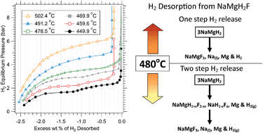
Hydrogen desorption PCI measurements were performed between 450 °C and 502 °C, Fig. 5, in order to determine the thermodynamics of hydrogen release. Desorption measurements below 470 °C show two clear desorption processes. As the temperature increases from 450 °C to 470 °C there is a shortening of the first desorption plateau relative to the second. By 478 °C, the first plateau has almost disappeared and the desorption curves are more consistent with the hydrogen existing as a randomly distributed solid solution rather than a stoichiometric hydride phase. This lack of flat plateaux is a disadvantage from an engineering perspective where absorption and desorption of hydrogen at a constant pressure is ideal.
![]() | ||
Fig. 5 Hydrogen desorption Pressure–Composition-Isotherms (PCI) for NaMgH2F performed between 450 °C and 502 °C. |
Because of their difference in shape, the desorption curves above and below 470 °C were treated separately for determining the thermodynamics of hydrogen release via the construction of van't Hoff plots. Each curve was numerically fitted so that the enthalpy and entropy could be determined at a consistent hydrogen content. The van't Hoff plots for hydrogen desorption values beyond −2.0 wt% showed a poor linear fit and were not considered further. The poor fits are possibly due to small errors in the calculated leak rates that accumulate over the course of the desorption measurements that may compound at lower pressures. Fig. 6(a) shows the variation in desorption enthalpy for the PCI curves measured above and below 470 °C as a function of hydrogen content. Above 470 °C the enthalpy slowly decreases from 100.3 kJ mol−1 H2 to 92.2 kJ mol−1 H2 between H2 desorption values of −0.5 wt% and −2.0 wt%. The enthalpy at the midpoint of full desorption is 96.8 kJ mol−1 H2. This is ∼10 kJ mol−1 H2 higher than for NaMgH3 decomposing into NaH and Mg,7 ∼20 kJ mol−1 H2 higher than for Mg2FeH6 and ∼23 kJ mol−1 H2 higher than for MgH2.6 The entropy (Fig. 6(b)) shows a similar trend in decreasing from 144.3 J mol−1 H2 K to 130.6 J mol−1 H2 K between desorption values of −0.5 wt% and −2.0 wt%.
![]() | ||
Fig. 6 (a) Variation in the hydrogen desorption enthalpy and (b) variation in the hydrogen desorption entropy of NaMgH2F. |
The variation in enthalpy and entropy for desorption below 470 °C is markedly different to that at higher temperatures. The enthalpy increases from 86.8 kJ mol−1 H2 to 98.2 kJ mol−1 H2 between a desorption value of −0.4 wt% and −1.1 wt%. Between −1.1 wt% and −1.2 wt% there is a discontinuity where the enthalpy spikes to 121.4 kJ mol−1 H2 before decreasing to 104.8 kJ mol−1 H2 by −2.0 wt% H2 desorption. The entropy at −0.4 wt% desorption begins at 126.9 J mol−1 H2 K and increases to 140.7 J mol−1 H2 K at −1.1 wt% desorption. Again, there is a discontinuity between −1.1 wt% and −1.2 wt% where the entropy spikes to 172.3 J mol−1 H2 K before decreasing to 148.1 J mol−1 H2 K by −2.0 wt% H2 desorption.
It should be noted that, below 470 °C, the enthalpy and entropy for the beginning of each desorption plateau of NaMgH2F is similar to that observed for each plateau in the desorption of NaMgH3. In the NaAlH4 system doped with fluorine, Eigen et al.40 observed partial hydrogen substitution in NaF and suggested an anion exchange mechanism between NaF1−yHy and fluorine rich Na3AlH6−xFx for the release of hydrogen. In a similar manner, we propose that the first hydrogen desorption plateau below 470 °C, eqn (6), has decomposition products of fluorine enriched NaMgH1+xF2−x and hydrogen rich NaH1−xFx. The second desorption plateau, is proposed to consist of anion exchange between NaMgH1+xF2−x and NaH1−xFx to form NaMgF3 and H2.
3NaMgH2F → 3/2NaMgH1+xF2−x + 3/2NaH1−xFx + 3/2Mg + 3/2H2 (for x ≪ 0.5) → NaMgF3 + 2Na(l) + 2Mg + 3/2H2 | (6) |
This was confirmed by performing a partial hydrogen desorption (−1.0 wt%) at 450 °C. XRD of the product (not shown) revealed the presence of Mg, NaH1−xFx and NaMgH1+xF2−x. The lattice parameter of the NaH1−xFx was contracted slightly to 4.859 Å, compared to the as-milled NaH value of 4.880 Å, that indicates partial substitution of H for F (NaF lattice parameter is 4.632 Å). The lattice parameters of NaMgH1+xF2−x (a = 5.477 Å, b = 7.688 Å and c = 5.393 Å) were, likewise, part-way between the original lattice parameters of NaMgH2F (a = 5.472 Å, b = 7.694 Å and c = 5.402 Å) and NaMgF3 (a = 5.486 Å, b = 7.674 Å and c = 5.370 Å).
Above 478 °C the desorption reaction of NaMgH2F can be represented as a single step reaction:
3NaMgH2F → NaMgF3 + 2Na(l) + 2Mg + 3H2 | (7) |
Hydrogen desorption from NaMgH2F above 478 °C occurs via the incremental concentration of F and the concurrent expulsion of Na and Mg from the perovskite phase, NaMgH2−yF1+y (for 0 ≤ y ≤ 2). The increase in stability of the perovskite NaMgH3 structure as a function of fluorine substitution for hydrogen14 and the fact that NaMgH3 and NaMgF3 form a complete solid solution series with H− and F− anions randomly distributed in the anionic sites,15 accounts for the shape of the observed hydrogen desorption curve.
For NaMgH2F to be considered as a concentrating solar thermal storage medium, operating temperatures above 478 °C are likely to be used given the low hydrogen desorption equilibrium pressures below this temperature. By assuming an operating temperature above 478 °C, by using the enthalpy at the midpoint of the desorption plateau (96.8 kJ mol−1 H2) and by assuming a theoretical H2 capacity of 2.95 wt%, the theoretical thermal storage capacity of NaMgH2F was determined to be 1416 kJ kg−1. This is only half the theoretical thermal storage capacity of MgH2 (2814 kJ kg−1) but, as suggested by Fig. 1 and discussed below, the higher enthalpy and operating temperature of NaMgH2F results in a cost advantage when considering coupled metal hydrides for concentrating solar thermal storage.
Material | Theoretical/practical H2 wt% | ΔH (kJ mol−1 H2) | Operating range (°C) | Operating pressure range (bar) | Practical density (kg m−3) | Thermal conductivity (W m−1 K−1) |
---|---|---|---|---|---|---|
a Ref. 6. b Ref. 7. c Estimated. d This work. | ||||||
MgH2 | 7.66/6.0 | 74a | 300–400 | 1.6–17 | 800a | 7 |
Mg2FeH6 | 5.47/5.0 | 77a | 385–470 | 7–37 | 1220a | 7 |
NaMgH3 | 4.01/3.3 | 86.6b | 475–575 | 7–37 | 1000c | 7 |
NaMgH2F | 2.95/2.5 | 96.8d | 510–605 | 7–37 | 1390d | 7 |
Material | Practical thermal energy stored (MWhth) | H2 mass (tons) | Metal mass in hydride (tons) | Mass of ENG (tons) | Metal hydride + ENG volume (m3) | Heat transfer area (m2) |
---|---|---|---|---|---|---|
MgH2, Ti1.2Mn1.8H3.0 | 5132 | 500 | 7822 | 390 | 10![]() |
67![]() |
28![]() |
1444 | 13![]() |
32![]() |
|||
Mg2FeH6, Ti1.2Mn1.8H3.0 | 4356 | 407 | 7739 | 387 | 6560 | 54![]() |
23![]() |
1178 | 10![]() |
26![]() |
|||
NaMgH3, Ti1.2Mn1.8H3.0 | 3851 | 320 | 9382 | 469 | 9594 | 53![]() |
18![]() |
926 | 8498 | 20![]() |
|||
NaMgH2F, Ti1.2Mn1.8H3.0 | 3704 | 276 | 10![]() |
537 | 7929 | 49![]() |
15![]() |
797 | 7313 | 17![]() |
The practical hydrogen weight capacity (as indicated in Table 2) has been used in the techno-economic assessment. The difference between the practical and the theoretical capacity varies for different high temperature metal hydrides (i.e. the practical capacity of MgH2 for solar thermal applications is only ∼78% of the theoretical value, 7.66 wt% of H2, while the practical capacity of Mg2FeH6 is ∼91% of the theoretical value, 5.47 wt% of H2).6 This results in a variation of the cost of the system material cost, as well as the containment volume and, hence, cost of the containment pressure vessel and heat exchanger as discussed in the following sections.
The NaMgH2F-system shows some promising characteristics. The hydrogen mass to be stored is almost 45% lower than that of the MgH2 system. This is due to the higher reaction enthalpy of the NaMgH2F material (more than 30% higher than MgH2), as well as the higher plant efficiency due to the increased operating temperature. As a consequence the LTMH mass decreases by the same percentage. However, based on the practical weight capacity of the materials, the mass of NaMgH2F material is approximately 37% higher than the corresponding MgH2 system value, since the hydrogen weight capacity of the NaMgH2F material is about 58% lower than that of MgH2 material. Likewise, the heat transfer area of the systems decreases, both for the high temperature and low temperature materials, with an increase in the high temperature hydride heat of reaction (i.e. decreasing of the hydrogen mass to be stored in the same storage time).
The installed costs of the four different Mg-based systems paired with Ti1.2Mn1.8H3.0 are reported in Fig. 7. The costs of the high temperature and low temperature material (including additional material handling and processing) and high-temperature heat exchanger and low-temperature heat exchanger (including heat exchanger and pressure vessel cost) are shown. The NaMgH2F based system shows that, despite requiring ∼58 wt% more HTMH, the overall installed cost decreases by approximately 37% compared to the corresponding MgH2 system cost and by approximately 18% relative to the NaMgH3 system. For all the selected systems, the low temperature material cost is the most significant item, representing approximately 59% of the overall NaMgH2F system cost and about 67% of the overall MgH2 system cost. The large contribution to the overall installed cost from the LTMH considered here (Ti1.2Mn1.8H3.0), despite being one of the lowest cost intermetallic hydrides, is due to a combination of both its low hydrogen capacity and the relatively high cost of titanium compared to the elements comprising the high-temperature metal hydrides. The result of this analysis is that the most effective way to reduce the overall installed cost of a coupled metal hydride concentrating solar thermal storage system is to reduce the quantity of hydrogen to be stored. This results in a decrease of: (1) the LTMH material cost, and (2) the LTMH heat exchanger cost, due to the decrease of the thermal power to be exchanged. The LTMH heat exchanger cost decrease from the MgH2 to the NaMgH2F system is on the order of 30%. With the assumptions made to evaluate the costs, regarding the HTMH costs: (1) the HTMH material cost when changing from MgH2 to NaMgH2F, decreases by almost 23%, mainly due to the reduced raw material cost and the amount of hydrogen required to be stored, despite the reduced weight capacity of the NaMgH2F system compared to MgH2; (2) the HTMH heat exchanger and pressure vessel cost when changing from MgH2 to NaMgH2F, decreases by about 18.5%, mainly due to the reduction of the thermal power to be exchanged and the decrease of the total volume (because of the higher material density).
Based on this cost analysis, NaMgH2F has advantages over the well-studied MgH2 as a solar thermal storage material that include: a higher enthalpy of hydrogen absorption/desorption; a higher operating temperature; a reduction in the quantity and cost of LTMH required, that also reduces the volume and cost of the LTMH containment vessel and; a higher practical density that reduces the volume and cost of the HTMH containment vessel. The disadvantages of NaMgH2F compared to MgH2 include: a sloping plateau; insufficient hydrogen absorption kinetics at 450 °C and; some loss of metallic sodium and magnesium from the system upon hydrogen cycling. Whilst the sloping plateau is an intrinsic feature of NaMgH2F, the potential cost savings of NaMgH2F over other Mg-based hydrides means that further work on improving the kinetics of hydrogen absorption and minimizing sodium and magnesium loss and assessment of the long term cyclic stability of NaMgH2F is required.
The analysis reported here represents a preliminary techno-economic assessment of the proposed storage system (NaMgH2F) with the aim of comparing its performance with that of the other Mg-based metal hydride storage systems. All the coupled systems show a preliminary specific cost on the order of 50–60 $ per kWhth. This cost is on the same order of the values available in the literature for molten salt technology41,42 which range from 30–80 $ per kWhth but a more thorough assessment taking into account the levelised cost of energy (LCOE) is required. However, the new storage system presented here is based on typical current values of the CSP plant properties (e.g. power plant efficiencies, storage time, plant capacity factor, etc.) and only consolidated technologies are examined (e.g. typology of heat exchangers, materials, etc.). Possible future techno-economic improvements of the CSP plant, which result in a remarkable reduction of the system installed cost, will be considered as part of another publication.35 Additional factors that could influence the ultimate cost of a concentrating solar thermal storage system based on coupled metal hydrides include: (1) an assessment of the kinetics of paired metal hydride systems, as differences in hydrogen absorption/desorption kinetics between the paired metal hydrides may place additional constraints/costs on the system; (2) variations in the practical achievable densities of metal hydride powders compacted with ENG needs to be considered and explored; (3) the slope of the hydrogen absorption/desorption curve/plateau (such as for NaMgH2F) that can result in parasitic energy losses; (4) the heat capacities of the metals/metal hydrides, ENG and shell/tube/heat exchangers that have not been included in this assessment and would serve to act as thermal ballast and decrease the quantity and cost of metal hydrides required and; (5) the hydrogen equilibrium pressure of an intermetallic LTMH that may need to be altered by the addition of suitable transition metals (such as, Ti, Zr, V, Cr or Fe as some possible examples) that may increase its cost.
This journal is © The Royal Society of Chemistry 2014 |