Efficient mixed metal oxide routed synthesis of boron nitride nanotubes
Jeghan Shrine Maria Nithyaa and
Arumugam Pandurangan*ab
aDepartment of Chemistry, Anna University, Chennai-600025, Tamilnadu, India. E-mail: pandurangan_a@yahoo.com; Fax: +91-44-2220060; Tel: +91-44-22358653
bInstitute of Catalysis and Petroleum Technology, Anna University, Chennai-600025, Tamilnadu, India
First published on 15th April 2014
Abstract
Boron nitride nanotubes (BNNTs) were successfully synthesized by a simple annealing process. Amorphous boron powder (B) was used as boron source to react with various metal oxide mixtures (V2O5/Fe2O3 and V2O5/Ni2O3). V2O5 acts as an efficient promoter in the synthetic process due to its highly oxidizing and reducing properties. The Fe2O3 and Ni2O3 act as catalysts in combination with the B/V2O5 system to achieve highly crystalline BNNTs at 1100 °C. The morphology and crystalline nature of the BNNTs were characterised by transmission electron microscopy (TEM), X-ray diffraction (XRD) and Raman spectroscopy. The observations revealed the hexagonal-BN (h-BN) phase of the BNNTs, with a highly crystalline tubular structure. This method proved to be simple and economical, using B/V2O5/Fe2O3 and B/V2O5/Ni2O3 mixtures for the large scale production of BNNTs.
1. Introduction
One dimensional (1D) nanomaterials, including nanotubes, nanowires, nanorods and nanobelts, have drawn extensive attention in various areas such as electronics, electrical, pharmaceuticals, cosmetics and biomedical applications.1,2 Among various 1D nanostructures, the most exciting classes of nanotubes are carbon nanotubes (CNTs) and boron nitride nanotubes (BNNTs). Owing to their structural similarities, BNNTs possesses several advantages over CNTs.3 BNNTs exhibit excellent mechanical, electrical and electronic properties, thermal stability, resistance to oxidation and a wide band gap, independent of geometric parameters.4 The theoretical perspective of BNNTs was first proposed by Rubio et al. in 1994, and in the subsequent year BNNT production was achieved by Chopra et al.5,6The most popular methods, such as arc-discharge, laser ablation, ball milling, template assisted synthesis and plasma jet synthesis, have failed to synthesis BNNTs of high purity and in a high yield.7 The chemical vapor deposition (CVD) technique is considered to be a simple method for the production of BNNTs using various liquid precursors such as diborane (B2H6), borazine (B3N3H6) and trimethyl borate (C3H9BO3).8−11 The drawback in this reaction process is the in situ generation of liquid vapors. To date, the boron oxide chemical vapor deposition (BOCVD) method yields large quantities of BNNTs. This method mainly utilizes MgO as a support (B/MgO, B/MgO/Fe2O3 and B/MgO/SnO) for the growth of BNNTs.12 Pakdel et al. (2012) reported the formation of well structured BNNTs by the annealing of B/FeO/MgO.13 Further, Ozmen et al. (2013) explained the formation of BNNT over amorphous B and Fe2O3.14 Li et al. (2011) have reported the synthesis of BNNT over a stainless steel substrate by annealing amorphous B and Fe2O3.15
Apart from using metal oxides as supports, there have also been reports of the production of BNNTs using the self propagation high temperature synthesis (SHS) method,16 and the formation of multi-walled and double walled BNNTs by catalytic chemical vapor deposition (CCVD) aided by a floating nickel catalyst.17 A nano-templated reaction, using single-walled carbon nanotubes (SWCNTs) as a template and ammonia borane complex (ABC) precursors was also reported by Nakanishi et al.18 Colemanite (Ca2B6O11·5H2O) mixed with ZnO, Al2O3, Fe3O4, and Fe2O3 has also produced BNNTs.19 However, all these reported approaches have various disadvantages, either in the selection of precursors with complex operational equipment setup or the requirement of growth temperatures >1200 °C. In the current scenario, BNNT synthesis on a large scale is considered a necessity for various commercial applications in catalysis, drug delivery, storage, nanoencapsulation, transport of various molecules and medical diagnosis.20–22
In order to circumvent the above problems, the present investigation focuses on the preparation of BNNTs at relatively lower temperatures and with simpler processes compared to existing approaches. In this context, a thermal CVD method was selected for the production of high quantities of BNNTs by heating boron with metal oxides. Here we have investigated a pair of reaction mixtures, B/V2O5/Fe2O3 and B/V2O5/Ni2O3, for the synthesis of BNNTs. V2O5, which can act as a promoter, oxidizer and a support, is introduced in the reactions. The motivation for the selection of V2O5 lies in the creative work of Goldberg et al.23 Fe2O3 and Ni2O3 are selected as catalysts due to their high catalytic efficiency towards nanotube formation.24 Metastable Ni2O3 was chosen because it can be easily reduced to NiO or Ni, which leads to the formation of BNNTs at lower temperatures.25 Already our group has been successful in the production of BNNTs using MoO3 as a promoter and using Fe2O3 and Ni2O3 as catalysts.26
In the present investigation, V2O5 undergoes reduction and also oxidizes boron at low temperatures. Simultaneously, boron reacts with Fe2O3/Ni2O3 and generates B2O2 vapor. The large amount of B2O2 vapor formed during this process reacts with NH3, forming BN. Fe/Ni, which attains a liquid state, facilitates the formation of BNNTs. The color of the amorphous boron mixture (B/V2O5/Fe2O3 and B/V2O5/Ni2O3) changes from dark brown to white, and this observation further confirms the formation of BNNTs. The effect of reaction temperature on the growth of BNNTs was studied and morphological changes, such as the tube structure and tube diameter, were also investigated using TEM studies. The role of V2O5 in the synthetic process was also explained in detail.
2. Experimental
2.1 Materials
Amorphous boron powder (Loba Chemie. Pvt. Ltd), Fe2O3 (Central Drug House), V2O5 and Ni2O3 (Sisco Research Laboratories Pvt. Ltd) were purchased and used as received. NH3 and N2 gases were used as the N source and carrier gas, respectively.2.2 Synthesis of boron nitride nanotubes
In this synthesis, a simple annealing process was adopted as reported by Tang et al.27 The reactions were performed in a horizontal tubular furnace, consisting of an alumina tube. The reactant mixtures, B/V2O5/Fe2O3 or B/V2O5/Ni2O3, were mixed adequately with the weight ratio 2![[thin space (1/6-em)]](https://www.rsc.org/images/entities/char_2009.gif) :
:![[thin space (1/6-em)]](https://www.rsc.org/images/entities/char_2009.gif) 1
1![[thin space (1/6-em)]](https://www.rsc.org/images/entities/char_2009.gif) :
:![[thin space (1/6-em)]](https://www.rsc.org/images/entities/char_2009.gif) 1 and loaded in an alumina boat. The boat was placed at the center of the tubular furnace. The ends of the alumina tube were closed with steel lids, carrying a gas inlet and outlet. Initially, the furnace was programmed with a ramp rate of 5 °C min−1 and heated to 900 °C under N2 gas flow (50 sccm) to eliminate the residual air. Then the temperature was raised to 1000–1200 °C and maintained for 1 h in an NH3 atmosphere (50 sccm). After this time, the furnace was slowly cooled to room temperature under an N2 atmosphere.
1 and loaded in an alumina boat. The boat was placed at the center of the tubular furnace. The ends of the alumina tube were closed with steel lids, carrying a gas inlet and outlet. Initially, the furnace was programmed with a ramp rate of 5 °C min−1 and heated to 900 °C under N2 gas flow (50 sccm) to eliminate the residual air. Then the temperature was raised to 1000–1200 °C and maintained for 1 h in an NH3 atmosphere (50 sccm). After this time, the furnace was slowly cooled to room temperature under an N2 atmosphere.
The as-synthesized samples were weighed and purified by stirring with 2 M HCl solution for 6 h at room temperature. The product was further treated with 1 M HNO3 for 24 h at 50 °C, to remove all the metal particles and amorphous boron powder. Finally, it was filtered, washed with distilled water and dried at 100 °C.28
2.3 Characterization methods
The crystalline structure of the samples was investigated by X-ray diffraction (XRD) analysis using a Cu Kα (λ = 1.54 Å) radiation source at room temperature, operated at 40 kV, 230 mA, at a scan rate of 0.02° (2θ) per s from 10 to 80° (2θ). The Fourier transform-infrared (FT-IR) spectra were recorded on a Perkin Elmer spectrophotometer. The morphological changes of the samples were studied by scanning electron microscopy (SEM, JEOL-840) and their elemental compositions were identified by energy dispersive spectroscopy (EDS). Nanostructures were viewed by a transmission electron microscopy (TEM, JEOL-2100) instrument operated at 200 kV. In the analysis, the samples were ultrasonically dispersed in acetone and dropped onto a carbon-coated copper grid. Raman spectroscopy analysis was performed using a WITec alpha 300R instrument with the 532 nm laser line from a Nd:YAG source. X-ray photoelectron spectroscopy (XPS) was performed using an Omicron Nanotechnology GMBH spectrometer employing a monochromatic Al Kα (1486.6 eV) X-ray source. All XPS profiles were corrected according to the binding energy of carbon (C–C) at 284.6 eV.3. Results and discussion
3.1 Structural and morphological studies of BNNTs
 | ||
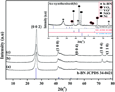
| Fig. 1 XRD patterns of BNNT formed over B/V2O5/Fe2O3 at (a) 1000 °C, (b) 1100 °C, (c) 1200 °C. The inset shows the XRD pattern of the as-synthesized sample obtained at 1100 °C. | ||
The XRD patterns in Fig. 1a–c show the reflections of the h-BN phase at (002), (100), (101), (102), (004), (104) and (110). It is also observed that the crystallinity of the h-BN phase increases with increasing temperature. In Fig. 1b, the diffraction of h-BN at 2θ values of 26.5°, 41.7°, 43.5°, 50.6°, 54.6°, 72.5° and 75.6° corresponds to interplanar spacings of 3.36, 2.16, 2.07, 1.80, 1.67, 1.30 and 1.25 Å respectively. The calculated lattice constant values, a = 2.49 and c = 6.72 Å ,are consistent with JCPDS file no.: 85-1068.
Fig. 2 shows the XRD pattern of the BNNTs formed over B/V2O5/Ni2O3 at 1000, 1100 and 1200 °C. The inset XRD pattern represents the as-synthesized product obtained at 1100 °C. This XRD pattern showed peaks related to h-BN, NiO, Ni, VO2 and VO. The formation of the NiO and Ni phases is due to the reduction of Ni2O3. The characteristic peaks at 2θ values of 37.3° and 43.2° correspond to the NiO phase (JCPDS file no.: 89-3080). Similarly, the peak at a 2θ value of 44.4° corresponds to Ni (JCPDS file no.: 88-2326). The presence of the other two phases, VO2 and VO, is due to the reduction of V2O5, which was observed as in the case of B/V2O5/Fe2O3. The diffraction peaks at 2θ values of 26.29°, 42.4° and 76.38° form the fingerprint of the h-BN phase.
 | ||
| Fig. 2 XRD patterns of BNNT formed over B/V2O5/Ni2O3 at (a) 1000 °C, (b) 1100 °C, (c) 1200 °C. The inset shows the XRD pattern of the as-synthesized sample obtained at 1100 °C. | ||
Fig. 2a–c represents the XRD pattern of purified BNNT formed over B/V2O5/Ni2O3. The entire diffraction pattern depicts the formation of (002), (100), (004), (104) and (110) planes related to h-BN. It is observed that the peaks related to metal oxide were totally absent. Noteworthy, the intensity of the peaks relating to the h-BN phase increase with increasing temperature. In Fig. 2b, the calculated d-spacing values of 3.39, 2.17, 1.68, 1.30 and 1.25 Å correspond to the (002), (100), (004), (104) and (110) planes, respectively. The lattice constants, a = 2.50 and c = 6.77 Å, were found to match with JCPDS file no.: 34-0421.
The presence of Fe2O3 and Ni2O3 in the reactant mixture plays a vital role in the formation of BNNTs. In general, Fe and Ni catalyze the reaction and influence the formation of BNNTs. In this study, Fe2O3 and Ni2O3 completely reduce to Fe and Ni respectively. Although NiO is more stable than Ni2O3, the formation of Ni by reduction is more possible at lower temperatures while using Ni2O3.25
 | ||
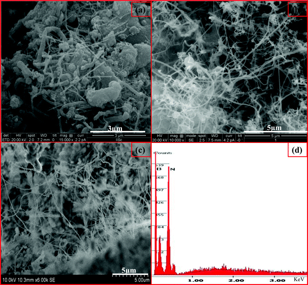
| Fig. 3 SEM images of BNNTs formed over B/V2O5/Fe2O3 at (a) 1000 °C, (b) 1100 °C and (c) 1200 °C, and (d) EDAX spectrum obtained of the BNNTs at 1100 °C shown in image (b). | ||
Similarly, the SEM images of as-synthesised products, obtained using B/V2O5/Ni2O3 at various temperatures, 1000, 1100 and 1200 °C, are shown in Fig. 4. It was observed that BNNTs were grown at 1000 °C. The theoretical background to this reaction process states that the metastable Ni2O3 starts to decompose at 600 °C and a liquid to solid state transition (NiO) occurs at an earlier stage. As stated earlier, V2O5 decomposed to VO2 and VO and attained a liquid state above 953 °C. Both these reduction reactions in turn oxidize boron and generate enormous amounts of B2O2 vapors. When the temperature reaches 1000 °C, these B2O2 vapors react with NH3 gas and promote the precipitation of BN over the Ni catalyst. The nucleation process initiates the growth of nanotubes by layer deposition on the surface of the catalyst, which tends to form BNNTs as shown in Fig. 4a. The maximum yield of BNNTs was obtained at 1100 °C compared to other temperatures. Fig. 4d presents the EDS spectrum of BNNT obtained, depicting the presence of B and N. The additional peaks in Fig. 4d originate from unreacted species.
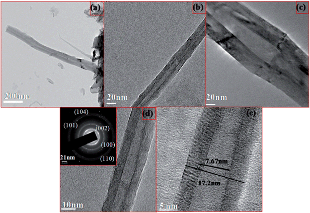
The morphologies of BNNTs synthesised from B/V2O5/Ni2O3 at 1100 °C were studied by TEM analysis as shown in Fig. 6. The TEM images of the as-synthesised BNNTs are shown in Fig. 6a. We can see from Fig. 6a that the tubes are straight in shape and have originated from the support. These tubes were comparatively longer with a smaller diameter than the tubes formed over B/V2O5/Fe2O3. Fig. 6b–e denotes the TEM images of purified BNNTs taken at various magnifications. The lengths of the tubes were found to be >1 μm. The bunching of BNNTs and multi-walled layers can be clearly identified from the TEM images. The tubes had both opened and closed ends. The inset SAED pattern shown in Fig. 6c corresponds to the (002), (100), (004), (104) and (110) crystalline planes of the h-BN structure, which coincide with the XRD analysis. These results confirm the formation of highly crystalline BNNTs. The BNNTs obtained in our case were similar in morphology to those reported by Zhi et al.30 The inner and outer diameters of the tubes were found to be 5.16 and 10.96 nm, respectively.
 | ||
| Fig. 9 XPS spectra of purified BNNTs formed over B/V2O5/Fe2O3 at 1100 °C; (a) the survey spectrum, (b) B 1s and (c) N 1s. | ||
 | ||
| Fig. 10 XPS spectra of purified BNNTs formed over B/V2O5/Ni2O3 at 1100 °C; (a) the survey spectrum, (b) B 1s and (c) N 1s. | ||
Fig. 10a shows the survey spectrum of BNNTs formed over B/V2O5/Ni2O3. This indicates the presence of boron and nitrogen in the BNNTs. The individual spectra of boron and nitrogen are shown in Fig. 10b and c, respectively. The peaks at 190.1 and 188.9 eV correspond to the B 1s band and are attributed to B–N bonding. The N 1s peaks at 397.9 and 396.5 eV indicate N–B bonding of h-BN.38
| Samples | % yield | XRD | TEM | Raman | XPS |
|---|---|---|---|---|---|
| B/V2O5/Fe2O3 | 97.8 | h-BN phase | Inner dia. – 7.67 nm, outer dia. – 17.2 nm | h-BN | h-BN |
| B/V2O5/Ni2O3 | 98.5 | h-BN phase | Inner dia. – 5.17 nm, outer dia. – 10.9 nm | h-BN | h-BN |
![[double bond, length as m-dash]](https://www.rsc.org/images/entities/char_e001.gif) N–H vapors, as shown in eqn (A2). These vapors might be adsorbed and activated by the Fe/Ni clusters in the molten liquid to form BNNTs. The clusters decomposed HO–B
N–H vapors, as shown in eqn (A2). These vapors might be adsorbed and activated by the Fe/Ni clusters in the molten liquid to form BNNTs. The clusters decomposed HO–B![[double bond, length as m-dash]](https://www.rsc.org/images/entities/char_e001.gif) N–H to form BN, which might subsequently react on the surface of the catalyst to form BNNTs.
N–H to form BN, which might subsequently react on the surface of the catalyst to form BNNTs.| 10B(s) + 2V2O5(s) + 2Fe2O3(s) ⇄ 5B2O2(g) + 2VO2(s,l) + 2VO(s,l) + 4Fe | (A1) |
 | (A2) |
Also, the mechanism of formation of BNNTs from B/V2O5/Ni2O3 was similar to the above process, except for the formation of NiO and Ni. The formation of NiO and Ni was confirmed by XRD. Hence, this study establishes that V2O5 is an efficient oxidizing agent.
4. Conclusion
In summary, through a simple annealing approach, BNNTs were successfully synthesized. These BNNTs have distinct characteristics with controlled diameters and long lengths. The formed BNNTs were found to be of the h-BN phase and of high crystallinity. This method can be extended to the synthesis of various BN based nanostructures. The synthesized BNNTs can be used as nanovectors in the future due to their non-toxic nature.Acknowledgements
One of the authors, Jeghan Shrine Maria Nithya, is thankful to the AICTE for the award of the NDF (National Doctorial Fellowship) and also to the Department of Chemistry, for providing the facilities sponsored by the DST (FIST).References
- Y. Chen, C. P. Li, H. Chen and Y. Chen, Sci. Technol. Adv. Mater., 2006, 7, 839–846 CrossRef CAS PubMed.
- Z.-G. Chen, J. Zou, G. Liu, F. Li, Y. Wang, L. Wang, X.-L. Yuan, T. Sekiguchi, H.-M. Cheng and G. Q. Lu, ACS Nano, 2008, 2, 2183–2191 CrossRef CAS PubMed.
- I. Capek, Adv. Colloid Interface Sci., 2009, 63–89 CrossRef CAS PubMed.
- C. Zhi, Y. Bando, C. C. Tang, S. Honda, K. Sato, H. Kuwahara and D. Golberg, Angew. Chem., Int. Ed., 2005, 150, 7932–7935 CrossRef PubMed.
- A. Rubio, J. L. Corkill and M. L. Cohen, Phys. Rev. B: Condens. Matter Mater. Phys., 1994, 5081 CrossRef CAS.
- N. G. Chopra, R. J. Luyken, K. Cherrey, V. H. Crespi, M. L. Cohen, S. G. Louie and A. Zettl, Science, 1995, 49, 966–967 CrossRef PubMed.
- C. Zhi, Y. Bando, C. C. Tang and D. Golberg, Mater. Sci. Eng., R, 2010, 70, 92–111 CrossRef PubMed.
- L. Guo and R. N. Singh, Phys. E., 2009, 41, 448–453 CrossRef CAS PubMed.
- C. Y. Su, Z. Y. Juang, K. F. Chen, B. M. Cheng, F. R. Chen, K. C. Leou and C. H. Tsai, J. Phys. Chem. C, 2009, 113, 14681–14688 CAS.
- O. R. Lourie, C. R. Jones, B. M. Bartlett, P. C. Gibbons, R. S. Ruoff and W. E. Buhro, Chem. Mater., 2000, 12, 1808–1810 CrossRef CAS.
- M. J. Kim, S. Chatterjee, S. M. Kim, E. A. Stach, M. G. Bradley, M. J. Pender, L. G. Sneddon and B. Maruyama, Nano Lett., 2008, 8, 3298–3302 CrossRef CAS PubMed.
- J. Wang, C. H. Lee and Y. K. Yap, Nanoscale, 2010, 2, 2028–2034 RSC.
- A. Pakdel, C. Zhi, Y. Bando, T. Nakayama and D. Golberg, Nanotechnology, 2012, 23, 215601 CrossRef PubMed.
- D. Ozmen, N. A. Sezgi and S. Balci, Chem. Eng. J., 2013, 219, 28–36 CrossRef CAS PubMed.
- J. Li, H. Lin, Y. Chen, Q. Su and Q. Huang, Chem. Eng. J., 2011, 174, 687–692 CrossRef CAS PubMed.
- J. Wang, L. Zhang, Y. Gu, X. Pan, G. Zhao and Z. Zhang, Mater. Res. Bull., 2013, 48, 943–947 CrossRef CAS PubMed.
- S. Chatterjee, M. J. Kim, D. N. Zakharov, S. M. Kim, E. A. Stach, B. Maruyama and L. G. Sneddon, Chem. Mater., 2012, 24, 2872–2879 CrossRef CAS.
- R. Nakanishi, R. Kitaura, J. H. Warner, Y. Yamamoto, S. Arai, Y. Miyata and H. Shinohara, Sci. Rep., 2013, 3, 1385 Search PubMed.
- S. Kalay, Z. Yilmaz and M. Culha, Beilstein J. Nanotechnol., 2013, 4, 843–851 CrossRef CAS PubMed.
- M. Corrias, B. Caussat, A. Ayral, J. Durand, Y. Kihn, P. Kalck and P. Serp, Chem. Eng. Sci., 2003, 58, 4475–4482 CrossRef CAS.
- Z.-G. Chen, J. Zou, Q. Liu, C. Sun, G. Liu, X. Yao, F. Li, B. Wu, X.-L. Yuan, T. Sekiguchi, H.-M. Cheng and G. Q. Lu, ACS Nano, 2008, 8, 1523–1532 CrossRef PubMed.
- R. H. Baughman, A. A. Zakhidov and W. A. D. Heer, Science, 2002, 297, 787–792 CrossRef CAS PubMed.
- D. Golberg, Y. Bando, K. Kurashima and T. Sato, Solid State Commun., 2000, 116, 1–6 CrossRef CAS.
- C.-Y. Su, W.-Y. Chu, Z.-Y. Juang, K.-F. Chen, B.-M. Cheng, F.-R. Chen, K.-C. Leou and C.-H. Tsai, J. Phys. Chem. C, 2009, 113, 14732–14738 CAS.
- S. Yang and J.-S. Kim, J. Korean Phys. Soc., 2010, 56, 659–665 CrossRef CAS.
- J. S. M. Nithya and A. Pandurangan, J. Nanosci. Nanotechnol., 2012, 12, 1–7 CrossRef PubMed.
- C. C. Tang, M. L. de la chapelle, P. Li, Y. M. Liu, H. Y. Dang and S. S. Fan, Chem. Phys. Lett., 2001, 342, 492–496 CrossRef CAS.
- T. Oku, N. Koi, K. Suganuma, R. V. Belosludov and Y. Kawazoe, Solid State Commun., 2007, 143, 331–336 CrossRef CAS PubMed.
- H. Suito and D. R. Gasskell, Metall. Trans. B, 1971, 2, 3299 CrossRef CAS.
- C. Zhi, Y. Bando, C. C. Tan and D. Golberg, Solid State Commun., 2005, 135, 67–70 CrossRef CAS PubMed.
- X. Chen, X. Wang, J. Liu, Z. Wang and Y. Qian, J. Appl. Phys., 2005, 81, 1035–1037 CrossRef CAS.
- C. Peijun, C. Luyang, S. Liang, Y. Zeheng, Z. Aiwu, G. Yunle, H. Tao and Q. Yitai, Solid State Commun., 2005, 133, 621 CrossRef PubMed.
- H. Yu, X. Huang, G. Wen, T. Zhang, B. Zhong and H. Bai, Mater. Chem. Phys., 2011, 129, 30–34 CrossRef CAS PubMed.
- C. H. Lee, J. Wang, V. K. Kayatsha, J. Y. Huang and Y. K. Yap, Nanotechnology, 2008, 19, 455605 CrossRef PubMed.
- B. Zhong, L. Song, X. X. Huang, G. W. Wen and L. Xia, Mater. Res. Bull., 2011, 46, 1521–1523 CrossRef CAS PubMed.
- C. D. Wagner, Handbook of X-ray Photoelectron Spectroscopy, Perkin-Elmer Corporation, Minnesota, 1979 Search PubMed.
- J. Li, J. Li, Y. Yin, Y. Chen and X. Bi, Nanotechnology, 2013, 24, 365605 CrossRef CAS PubMed.
- A. Gomathi and C. N. R. Rao, Mater. Res. Bull., 2006, 41, 941 CrossRef CAS PubMed.
- V. G. Samsonov, The Oxide Handbook, Plenum Press, NewYork, 1973 Search PubMed.
- D. S. Su and R. Schlogl, Catal. Lett., 2002, 83, 115–119 CrossRef CAS.
- R. S. Wagner and W. C. Ellis, Appl. Phys. Lett., 1964, 4, 89–90 CrossRef CAS PubMed.
- C. C. Tang, S. S. Fan, P. Li, Y. M. Liu and H. Y. Dang, Mater. Lett., 2001, 51, 315–319 CrossRef CAS.
| This journal is © The Royal Society of Chemistry 2014 |


