Synthesis of three-dimensional self-standing graphene/Ni(OH)2 composites for high-performance supercapacitors
Chunhui Jianga,
Beibei Zhana,
Chen Lia,
Wei Huang*ab and
Xiaochen Dong*ab
aKey Laboratory for Organic Electronics & Information Displays (KLOEID), Nanjing University of Posts and Telecommunications, Nanjing 210023, China. E-mail: iamxcdong@njtech.edu.cn; iamwhuang@njtech.edu.cn
bJiangsu-Singapore Joint Research Center for Organic/Bio-Electronics & Information Displays and Institute of Advanced Materials (IAM), Nanjing Tech University, 30 South Puzhu Road, Nanjing 211816, China
First published on 25th March 2014
Abstract
Using surface active agents, three-dimensional (3D) self-standing graphene/Ni(OH)2 composites with different morphologies, such as nanoflowers, nanoslices and nanoparticles, are directly synthesized by a facile in situ electrodeposition method. SEM and Raman spectroscopy are used to investigate the morphologies and structures. Detailed electrochemical characterizations reveal that the 3D graphene/Ni(OH)2 nanoflower exhibits high specific capacitance (718.2 F g−1 at 6.7A g−1 in 6.0 M KOH aqueous solution) and good cycling performance (84.2% capacitance retention after 500 cycles) compared with those of other Ni(OH)2 morphologies. Nyquist plot investigation shows that 3D graphene/Ni(OH)2 nanoflowers present a low equivalent series resistance. These results indicate that the composite may be a promising candidate for high-performance supercapacitors.
Introduction
To date, a number of materials, including carbon-based materials, metal oxides/hydroxides, metal sulfides and conductive polymers, have been reported for the fabrication of supercapacitor electrodes.1–5 The carbonaceous materials are normally utilized for electrochemical double layer capacitors (EDLC), which have capacitive performances inferior to those of pseudocapacitors. The pseudocapacitors can supply high current densities during charge–discharge processes by oxidation–reduction reactions of active materials.6 However, certain electric insulativity of pseudo-active materials can hardly support fast electron transport at high rates. Therefore, many research groups have adhered pseudo-active materials to conductive substrates with polyvinylidene fluoride (PVDF) as the binder.7,8 However, this method not only drops the conductivity but also decreases the overall gravimetric specific capacitance of the composite electrodes. Thus, in situ growth of active materials on conductive substrates is an expedient strategy for preparing supercapacitor electrodes. The synergistic effects between the substrate and active materials can largely promote their electrochemical performances.9–11Graphene, with an atomic-scale honeycomb-crystal lattice, consists of single-layer sp2-hybridized carbon atoms. It possesses unusual mechanical strength, excellent transmittance, superb thermal conductivity, high electrical conductivity and large specific surface area.12,13 These properties enable graphene to have numerous applications in many fields, including field-effect transistors,14 transparent conductors,15 energy storage storages16–19 and biosensors.20,21 Graphene-based supercapacitors, novel green-energy storage devices, have presented outstanding performances with high energy density and ultra-long cycling life.22–25 However, their practical applications are severely restricted by the inclination of agglomeration between graphene sheets because of the strong π–π interaction. Recently, a novel 3D graphene foam with a large specific area and high electrical conductivity was synthesized by chemical vapor deposition to overcome the π–π interaction between graphene sheets.34 This foam is an ideal material for the preparation of electrochemical electrodes for high-performance supercapacitors.
Nickel hydroxide (Ni(OH)2), a material with low-cost and various morphologies, has seemed to be a promising candidate for high-performance supercapacitors. In order to improve the electrochemical properties of Ni(OH)2, nickel foam, carbon paper, carbon nanotube, reduced graphene oxide and graphene have been used to form composites with Ni(OH)2.26–31 The results demonstrated that these conductive materials can greatly reduce the resistivity of the composites and shorten the pathways of electron and ion diffusion, which leads to efficient charge exchange and mass transfer.
To meet the demand for energy and environment protection, we demonstrate a facile method of preparing 3D graphene/Ni(OH)2 composites for high-performance supercapacitors. Herein, 3D self-standing graphene foam is used as the conductive matrix for in situ electrodeposited Ni(OH)2 nanoparticles. To overcome the limitation that restricts metal materials from combining with hydrophobic graphene, sodium dodecyl benzene sulfonate (SDBS) and ethanol are used as surface active agents. The morphology of the 3D graphene/Ni(OH)2 is shown to be controlled by the surface active agents. Electrochemical measurements reveal that 3DG/Ni(OH)2 exhibits a high capacitance performance and excellent cycling stability.
Experimental section
Materials
NiSO4·6H2O, NaOH, KOH, hydrochloric acid, Na2SO4 and ethanol were analytical reagents purchased from Sinopharm Chemical Reagent Co. Ltd. SDBS was chemically pure and purchased from Shanghai LingFeng Chemical Reagent Co. Ltd. Nickel foam was supplied by Alantum Advanced Technology Materials Co. Ltd. All materials were used without any further purification.Synthesis of 3D graphene foam
Three-dimensional self-standing graphene foam was synthesized by chemical vapor deposition (CVD) method with nickel foam as the substrate and ethanol as the carbon source under atmospheric pressure.32 In a typical experiment, nickel foam was placed into a quartz tube and heated to 900 °C at a heating rate of 20 °C min−1. After annealing for 10 min to clean the nickel surface under hydrogen atmosphere, ethanol vapour was introduced into the quartz tube by bubbling hydrogen through ethanol liquid. After 20 min of growth, the substrate was rapidly cooled down to ambient temperature. After the growth process, the nickel substrates were etched by HCl solution (10%) at 80 °C overnight to obtain three-dimensional self-standing graphene foam.Preparation of 3D graphene/Ni(OH)2 composites
In this work, 5.0 mM Ni2SO4 dissolved in DI water or ethanol aqueous solution (30%) was used as electrolyte and Ni(OH)2 precursors. The pH value of the electrolyte was regulated between 7.00 and 8.00 with NaOH solution (0.1 M). Prior to electrodeposition, 3D graphene was immersed into an SDBS solution (1 mg ml−1) overnight to activate the graphene surface. All the electrodeposition was executed in a three-electrode system at room temperature. A saturated calomel electrode (SCE) and a Pt foil electrode were used as the reference electrode and counter electrode, respectively. Ni(OH)2 was electrodeposited for 300 s on 3D graphene at a potential of −1.0 V. After electrodeposition, the composites were cleaned with DI water and dried in air at 50 °C.Characterization
The structures of 3D graphene and graphene/Ni(OH)2 composite were characterized by JY HR800 micro-Raman spectroscopy (laser wavelength: 514 nm). The morphology and related EDS elemental mapping images were observed by field-emission scanning electron microscopy (FESEM, Hitachi S-4800, Japan). Thermogravimetric analyses (TGA) were conducted with a Shimadzu DTG-60H thermogravimetric analyzer with a heating rate of 5 °C min−1 under air atmosphere.Electrochemical tests
Electrochemical properties were analyzed by using a conventional three-electrode cell (CHI 660E, Chenhua, China) in 6.0 M KOH aqueous solution at ambient temperature. Free-standing 3D graphene/Ni(OH)2 composites with a mass of 1 mg acted as the work electrodes, whereas a platinum foil and a saturated calomel electrode (SCE) were used as the counter electrode and the reference electrode, respectively. Electrochemical impedance spectroscopy (EIS) tests were conducted in the frequency range from 10 kHz to 1 Hz at an open-circuit potential and at an ac perturbation of 5.0 mV.Results and discussion
Fig. 1a shows the low-magnification SEM image of the self-standing 3D graphene foam. It can be seen that the 3D graphene foam exhibits a macroporous structure with smooth, thin graphene skeleton. The pore diameter is about 100–200 μm, and the specific surface area of the 3D graphene is nearly 670 m2 g−1.33 The inset image presents a seamless continuous skeleton with micrometer-scale smooth topographic domains, assuming the identical surface topology as nickel substrate produced by conformal CVD growth. Raman spectra of the 3D graphene and the 3D graphene/Ni(OH)2 composite are shown in Fig. 1b. The Raman spectrum of 3D graphene presents two obvious characteristic vibration bands at 1583 cm−1 and 2717 cm−1, corresponding to the G and 2D band of graphene, respectively. This spectrum demonstrates that the 3D graphene foam consists of few layers without any defects, which ensured high electrical and mechanical performances.34 In addition to the characteristic peaks of graphene at 1583 cm−1 and 2717 cm−1, the as-prepared 3D graphene/Ni(OH)2 composites also present two peaks at around 514.2 cm−1 (longitudinal optical, LO) and 983.5 cm−1 (phonon modes, 2LO), indicating that Ni(OH)2 has been successfully deposited on the surface of 3D graphene foam.31,35,36 | ||
| Fig. 1 (a) SEM images of 3D graphene foam. The inset shows an enlarged view of the 3D graphene surface. (b) Raman spectra of 3D graphene and 3D graphene/Ni(OH)2 composite. | ||
Fig. 2 shows the SEM images of 3D graphene/Ni(OH)2 composites synthesized in different processes. It can be observed that the nanoflower, nanoslice, and nanoparticle morphologies of the resulting Ni(OH)2 nanostructures can be changed merely by changing the surfactant. This phenomenon may arise from the fact that the hydrophobicity of the graphene surface was overwhelmingly decreased, and the resulting Ni(OH)2 particles were able to grow uniformly on the surface of the graphene.37 When sodium dodecyl benzene sulfonate (SDBS) was used to reduce the water repellency of the 3D graphene, the Ni(OH)2 presented uniform nanoflower morphology and formed a highly ordered film that attached to the graphene surface (Fig. 1a and b). The diameters of the nanoflowers are about 500–600 nm, as shown in the inset image of Fig. 2b. It can be concluded that the SDBS content can be controlled at certain concentrations, in which the amount of Ni(OH)2 forms the flower-shaped nanostructure layer by self-assembly.38 On the contrary, the resulting Ni(OH)2 synthesized in ethanol solution (30%) solution presented uniform nanoslices morphology because ethanol eliminated the hydrophobicity of the graphene surface,39 as shown in Fig. 2c and d. The inset of Fig. 1d shows that the length and thickness of Ni(OH)2 nanoslices are about 300 nm and ∼50 nm, respectively. In the case with no pretreatment and the electrolyte application in the absence of additives, the resulting Ni(OH)2 film attached to the surface loosely and easily fell off, as shown in Fig. 2d. The magnification image in Fig. 2f demonstrates that Ni(OH)2 particles have an inhomogeneous distribution, indicating that the hydrophobicity of graphene strongly prevents crystal growth on its surface. The SEM images indicate that the surface-active agents and solution have a very important effect on the morphologies and sizes of Ni(OH)2 nanoparticles in the 3D graphene/Ni(OH)2 composites.
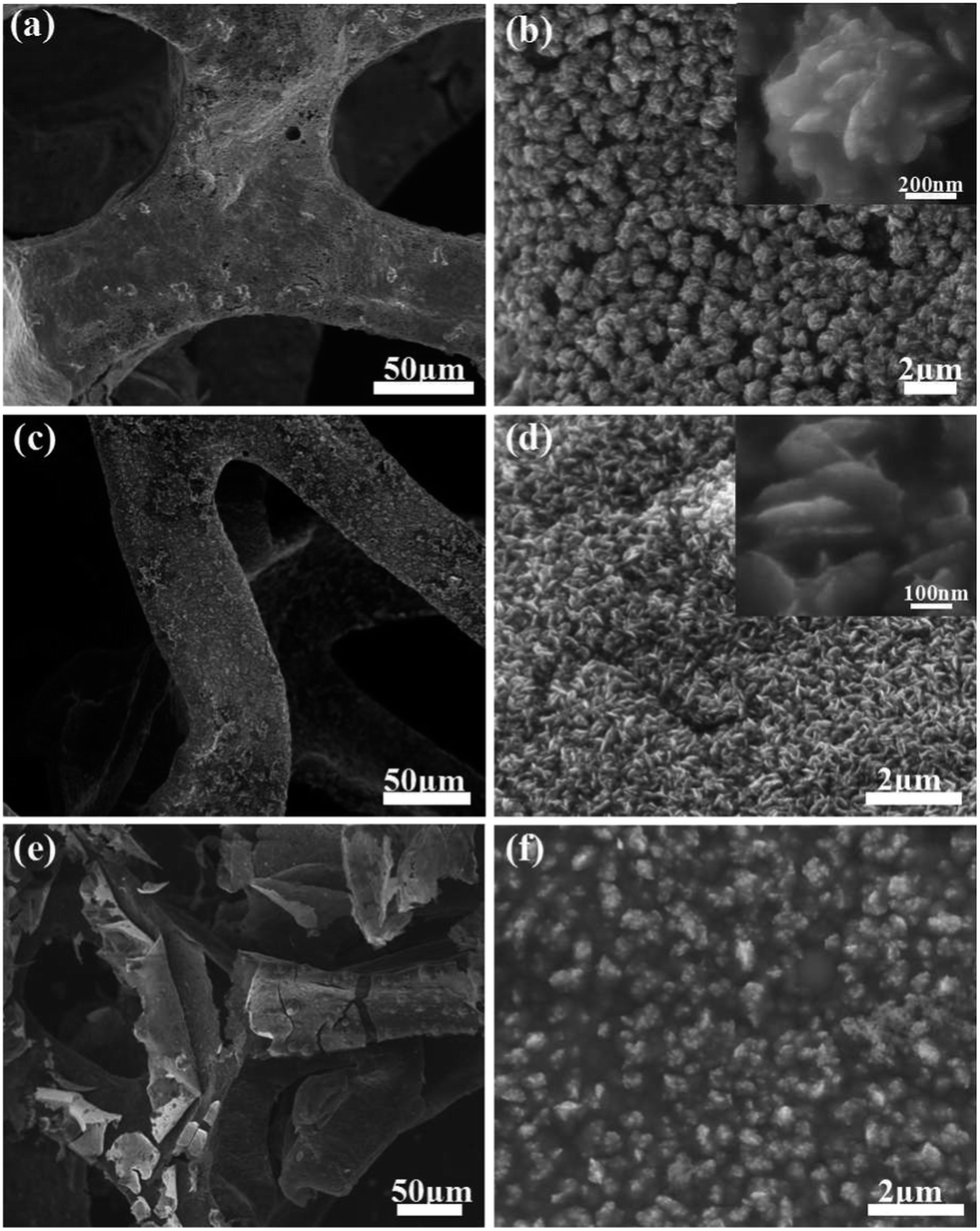 | ||
| Fig. 2 SEM images of synthesized 3D graphene/Ni(OH)2 composites showing different structures. (a and b) 3D graphene/Ni(OH)2 nanoflowers; the inset shows a magnified image. (c and d) 3D graphene/Ni(OH)2 nanoslices; the inset is an enlarged view. (e and f) 3D graphene/Ni(OH)2 nanoparticles. | ||
During the electrodeposition process, the Ni(OH)2 crystals developed onto the surface of the 3D graphene foam and formed different morphologies under the effect of surfactants. The structure and morphology of the 3D graphene/Ni(OH)2 nanoflower composite were also observed by EDS mapping measurement (Fig. 3). The elemental mapping images further reveal the uniform distribution of oxygen and nickel throughout the 3D graphene framework, which further demonstrates that Ni(OH)2 nanoparticles were distributed homogeneously on the surface of the 3D graphene foam. The EDS spectrum provided in Fig. 3e indicates that the contents of carbon, oxygen, and nickel are approximately 18.33 wt%, 27.04 wt%, and 54.63 wt%, respectively. In the spectrum, sulfur originates from the nickel sulfate.
 | ||
| Fig. 3 SEM images of (a) as-prepared 3D graphene/Ni(OH)2 nanoflowers and the related EDS elemental mapping images of (b) carbon, (c) oxygen, and (d) nickel. (e) EDS spectra of 3DG/NF. | ||
In order to investigate the accurate content of Ni(OH)2 in the 3DG/NF composite, thermogravimetric analyses (TGA) were carried out in air. As shown in Fig. 4, the 3D graphene remained at 8.0% of the mass after the TGA test, which is attributed to residual carbon.44 The TGA curve of 3DG/NF at 800 °C indicates NiO and 3D graphene. However, the thermogravimetric analyses indicate that the content of Ni(OH)2 is about 64.8% in the 3DG/NF composites.
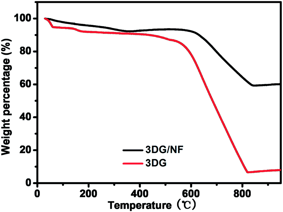 | ||
| Fig. 4 TGA curves of 3D graphene and 3DG/NF. | ||
The electrochemical performances of 3D graphene/Ni(OH)2 composites synthesized under different conditions were characterized by electrochemical working station, as shown in Fig. 5. As shown in Fig. 5a, the cyclic voltammetry (CV) curves were conducted at a scanning rate of 50 mV s−1. It is obvious that all of the composites presented a pair of typical oxidation and reduction peaks caused by the following reversible electrochemical reaction: Ni(OH)2 + OH− ↔ NiOOH + H2O + e−.40
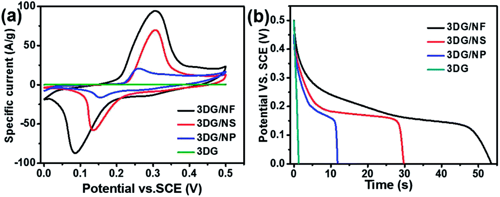 | ||
| Fig. 5 (a) CV curves of 3DG/Ni(OH)2 synthesized in different conditions at a scan rate of 50 mV s−1. (b) Discharge curves of 3D graphene/Ni(OH)2 composites and 3DG electrodes surveyed at a current density of 6.7 A g−1. | ||
The CV curves indicate that the 3D graphene/Ni(OH)2 nanoflowers (3DG/NF) exhibit the strongest redox peak current. In addition, the difference between the oxidation potential and the reduction potential is also larger compared to 3D graphene/Ni(OH)2 nanoslices (3DG/NS), 3D graphene/Ni(OH)2 nanoparticles (3DG/NP) and 3D graphene (3DG). The area surrounded by the CV curve of 3DG/NF is dramatically larger than those of other composites, indicating a large specific capacitance associated with the Ni(OH)2 nanoflowers. In Fig. 5b, the galvanostatic discharge test results further illustrate that 3DG/NF has an optimal gravimetric capacitance of 718.2 F g−1 at the current density of 6.7 A g−1, which is markedly larger than that of 3DG/NS (446.7 F g−1), 3DG/NP (177.2 F g−1), and 3DG (17.4 F g−1). Here, the specific capacitance is calculated by the following equation: C = I × Δt/(m × ΔV), where, C (F g−1) is the specific capacitance of the electrode, I (A) is the discharge current, Δt (s) is the discharge time, m (g) refers to the mass of the active materials and ΔV (V) is the potential window for the cycling test. This phenomenon may have occurred because the Ni(OH)2 nanoflowers possess a higher specific surface area than other morphologies.41
Nyquist plots in Fig. 6 show the electrochemical impedance spectroscopy of 3DG, 3DG/NF, 3DG/NS and 3DG/NP electrodes, respectively. The plots indicate that the 3DG/Ni(OH)2 composites exhibit a lower equivalent series resistance (ESR) than that of 3DG, which may greatly enhance the supercapacitor performance of the composite electrodes. In the high-frequency range, the axis intercept of four electrodes indicates that the 3DG/Ni(OH)2 composites possess the same internal resistances, which are lower than that of 3DG. The smallest semicircle diameter of 3DG/NF, related to the interfacial charge-transfer impendence (Rct), indicates that 3DG/NF possesses the lowest interfacial charge-transfer resistance. Moreover, the 3DG/NF exhibits a more vertical line, suggesting that the Warburg resistance is not a determining factor and that this kind of electrode can store charge more efficiently. All of these comparisons indicate that the 3DG/NF composite is the best candidate for the supercapacitor electrode.
 | ||
| Fig. 6 Nyquist plots of 3DG/NF and 3DG/NS, 3DG/NP and 3DG. | ||
Fig. 7a shows the cyclic voltammetry (CV) curves of the 3DG/NF electrode at varied scan rates with potential ranging from 0 to 0.5 V. Two strong oxidation and reduction peaks originating from the redox reaction between Ni(OH)2 and NiOOH can be clearly seen. With an increase in scanning rate, the peak current increases significantly. At the same time, the oxidation peaks drifted towards more positive values, while the reduction peaks drifted towards more negative values. This phenomenon occurred because external active sites only can support redox reactions completely during high scanning rates, which makes the internal diffusion resistance increase within the pseudoactive materials.32,33 The galvanostatic charge–discharge curves of the 3DG/NF electrode at different discharge current densities are shown in Fig. 7b. According to the equation, C = I × Δt/(m × ΔV), the specific capacitance of the 3DG/NF electrode is calculated to be about 718.2, 380.5, 327.2, 314.0 and 300.0 F g−1 at current densities of 6.7, 10.0, 13.3, 16.7 and 20.0 A g−1, respectively. The result indicates fast and efficient electrolyte ion diffusion to the active site surfaces and outstanding electron transfer within the 3D graphene framework. Fig. 7c shows that the specific capacitance dropped significantly between the current densities of 6.7 and 20.0 A g−1, which may have occurred because of insufficient time for active materials to respond completely at high current densities. The cycling stability of the 3DG/NF electrode was tested with 500 cycles of charge and discharge at a current density of 10.0 A g−1, as shown in Fig. 7d. As shown in the inset image, the charge–discharge curves display typical pseudocapacitance characteristics and excellent symmetry after a long time charge and discharge. More importantly, the specific capacitance decreased from 380.5 F g−1 to 320.4 F g−1 after 500 cycles, remaining at 84.2%. It can be concluded that the 3DG/NF electrode possesses excellent rate stability even with charge and discharge under high current densities, which makes it promising for the development of high-performance supercapacitors.
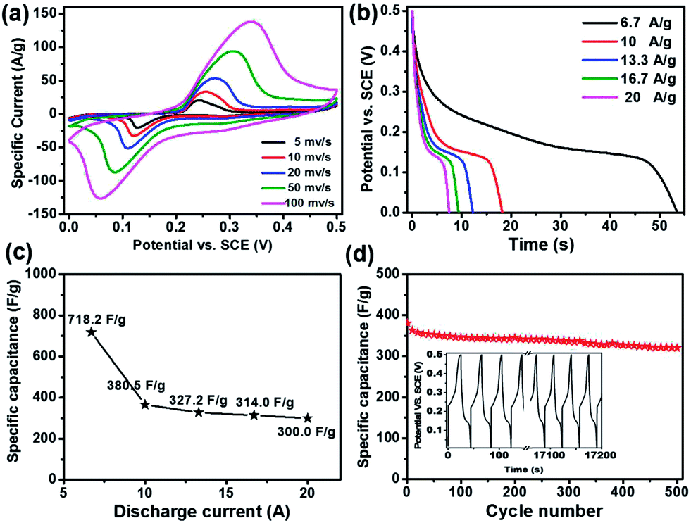 | ||
| Fig. 7 Electrochemical measurements of the 3DG/NF electrode in 6.0 M KOH aqueous solution. (a) CV curves at different scan rates. (b) Galvanostatic discharge curves at different current densities. (c) Effects of current density on its specific capacitance. (d) The cycling performance of 3DG/NF at a current density of 10.0 A g−1. The inset shows the charge–discharge curves of the 3DG/NF electrode at 10 A g−1. | ||
Compared with similar results listed in Table 1, the as-prepared 3DG/NF exhibits excellent specific capacitance even at high current densities and a wide potential window, which is probably due to the nanoflower structure of Ni(OH)2 particles and the high electrical conductivity of 3D graphene.26–29,36,42,43 This means the application of SDBS as a surfactant can control both the Ni(OH)2 structure and electrochemical performance.
| Electrode | Technique | Specific capacitance | Capacitance retention | Potential window | Cell type | Electrolyte | Ref. |
|---|---|---|---|---|---|---|---|
| Ni(OH)2/nickel foam | Electrodeposition | 3152 F g−1 (4 A g−1) | 52% (4 A g−1, 300 cycles) | −0.05–0.45 V | 3 ED | KOH (3%) | 26 |
| α-Ni(OH)2/rGO | Chemical precipitation | 521 F g−1 (50 mV s−1) | 87.9% (50 mV s−1, 1000 cycles) | 0.0–0.45 V | 3 ED | KOH (6 M) | 27 |
| Ni(OH)2/carbon fiber | Conformal coating | 1416 F g−1 (1 A g−1) | 66% (20 A g−1, 10![[thin space (1/6-em)]](https://www.rsc.org/images/entities/char_2009.gif) 000 cycles) 000 cycles) |
0.0–0.40 V | 3 ED | KOH (1 M) | 28 |
| Ni(OH)2/graphene | Hydrothermal | 166 F g−1 (0.5 A g−1) | 65% (10 A g−1, 1000 cycles) | 0.0–0.50 V | 3 ED | KOH (6 M) | 29 |
| Ni3S2@Ni(OH)2/graphene | Hydrothermal | 1037.5 F g−1 (5.1 A g−1) | 99.1% (5.1 A g−1, 2000 cycles) | −0.15–0.55 V | 3 ED | KOH (3 M) | 36 |
| β-Ni(OH)2 | Chemical precipitation | 398 F g−1 (5 mV s−1) | Unknown | 0.0–0.50 V | 3 ED | KOH (2 M) | 42 |
| NiO/graphene | Electrodeposition | 745 F g−1 (1.4 A g−1) | 115% (80 mV s−1, 2000 cycles) | 0.0–0.50 V | 3 ED | KOH (3 M) | 43 |
| Our 3DG/NF | Electrodeposition | 718.2 F g−1 (6.7 A g−1) | 84.2% (10 A g−1, 500 cycles) | 0.0–0.50 V | 3 ED | KOH (6 M) | Ours |
Conclusion
In summary, self-standing 3DG/Ni(OH)2 composites with different Ni(OH)2 morphologies of nanoflowers, nanoslices and nanoparticles were synthesized using a facile in situ electrodeposition method using surface active agents. The electrochemical measurements indicated that the 3DG/NF electrode exhibits better supercapacitor performance than that of 3DG/NS and 3DG/NP composites. The specific capacitance of 3DG/NF can reach 718.2 F g−1 at 6.7 A g−1, which is more outstanding than that of 3DG/NS (446.7 F g−1) and 3DG/NP (177.2 F g−1). Nyquist plots further reveal the more efficient electrolyte ion diffusion of 3DG/NF. In addition, the 3DG/NF electrode presents excellent cycling stability after 500 cycles. The self-standing 3D graphene/Ni(OH)2 composite can supply novel possibilities for energy storage devices and various other applications.Acknowledgements
The project was supported by Jiangsu Provincial Founds for Distinguished Young Scholars (BK20130046), the National Basic Research Program of China (2012CB933300), the NNSF of China (21275076, 61328401), the Key Project of Chinese Ministry of Education (212058), Program for New Century Excellent Talents in University (NCET-13-0853), Research Fund for the Doctoral Program of Higher Education of China (20123223110008), the Ministry of Education of China (IRT1148).References
- G. Y. Xu, B. Ding, P. Nie, L. F. Shen, H. Dou and X. G. Zhang, ACS Appl. Mater. Interfaces, 2014, 6, 194 CAS.
- X. M. Liu, Q. Long, C. H. Jiang, B. B. Zhan, C. Li, S. J. Liu, Q. Zhao, W. Huang and X. C. Dong, Nanoscale, 2013, 5, 6525 RSC.
- Z. Gao, W. L. Yang, Y. X. Yan, J. Wang, J. Ma, X. M. Zhang, B. H. Xing and L. H. Liu, Eur. J. Inorg. Chem., 2013, 27, 4832 CrossRef.
- S. J. Bao, C. M. Li, C. X. Guo and Y. Qiao, J. Power Sources, 2008, 180, 676 CrossRef CAS.
- G. A. Snooka, P. Kao and A. S. Best, J. Power Sources, 2011, 196, 1 CrossRef.
- Y. Zhang, H. Feng, X. B. Wu, L. Z. Wang, A. Q. Zhang, T. C. Xia, H. C. Dong, X. F. Li and L. S. Zhang, Int. J. Hydrogen Energy, 2009, 34, 4889 CrossRef CAS.
- H. L. Wang, L. F. Cui, Y. Yang, H. S. Casalongue, J. T. Robinson, Y. Y. Liang, Y. Cui and H. J. Dai, J. Am. Chem. Soc., 2010, 132, 13978 CrossRef CAS.
- Y. Wang, S. F. Yu, C. Y. Sun, T. J. Zhu and H. Y. Yang, J. Mater. Chem., 2012, 22, 17584 RSC.
- Z. S. Wu, D. W. Wang, W. C. Ren, J. P. Zhao, G. M. Zhou, F. Li and H. M. Cheng, Adv. Funct. Mater., 2010, 20, 3595 CrossRef CAS.
- J. Yan, T. Wei, B. Shao, Z. J. Fan, W. Z. Qian, M. L. Zhang and F. Wei, Carbon, 2010, 48, 487 CrossRef CAS.
- S. Chen, J. W. Zhu, X. D. Wu, Q. F. Han and X. Wang, ACS Nano, 2010, 2822 CrossRef CAS.
- S. Stankovich, D. A. Dikin, G. H. B. Dommett, K. M. Kohlhaas, E. J. Zimney, E. A. Stach, R. D. Piner, S. T. Nguyen and R. S. Ruoff, Nature, 2006, 442, 282 CrossRef CAS.
- P. C. Lian, X. F. Zhu, S. Z. Liang, Z. Li, W. S. Yang and H. H. Wang, Electrochim. Acta, 2010, 55, 3909 CrossRef CAS.
- F. Xia, D. B. Farmer, Y. Lin and P. Avouris, Nano Lett., 2010, 10, 715 CrossRef CAS.
- S. Bae, H. Kim, Y. Lee, X. F. Xu, J. S. Park, Y. Zheng, J. Balakrishnan, T. Lei, H. R. Kim and Y. Song, Nat. Nanotechnol., 2010, 5, 574 CrossRef CAS.
- H. L. Wang, H. S. Casalongue, Y. Y. Liang and H. J. Dai, J. Am. Chem. Soc., 2010, 132, 7472 CrossRef CAS.
- C. H. Xu, B. H. Xu, Y. Gu, Z. G. Xiong, J. Sun and X. S. Zhao, Energy Environ. Sci., 2013, 6, 1388 CAS.
- X. Wang, L. J. Zhi and K. Müllen, Nano Lett., 2008, 8, 324 Search PubMed.
- X. C. Dong, J. X. Wang, J. Wang, M. B. Chan-Park, X. A. Li, L. H. Wang, W. Huang and P. Chen, Mater. Chem. Phys., 2012, 134, 576 CrossRef CAS.
- Y. Y. Shao, J. Wang, H. Wu, J. Liu, I. A. Aksay and Y. H. Lin, Electroanalysis, 2010, 22, 1027 CrossRef CAS.
- Y. Liu, D. S. Yu, C. Zeng, Z. C. Miao and L. M. Dai, Langmuir, 2010, 26, 6158 CrossRef CAS.
- G. P. Wang, L. Zhang and J. J. Zhang, Chem. Soc. Rev., 2012, 41, 797–828 RSC.
- X. C. Dong, X. W. Wang, L. Wang, H. Song, X. G. Li, L. H. Wang, M. B. Chan-Park, C. M. Li and P. Chen, Carbon, 2012, 50, 4865 CrossRef CAS.
- C. G. Liu, Z. N. Yu, D. Neff, A. Zhamu and B. Z. Jang, Nano Lett., 2010, 10, 4863 CrossRef CAS.
- Y. W. Zhu, S. Murali, M. D. Stoller, K. J. Ganesh, W. W. Cai, P. J. Ferreira, A. Pirkle, R. M. Wallace, K. A. Cychosz, M. Thommes, D. Su, E. A. Stach and R. S. Ruoff, Science, 2011, 332, 1537 CrossRef CAS.
- G. W. Yang, C. L. Xu and H. L. Li, Chem. Commun., 2008, 6537 RSC.
- J. W. Lee, T. Ahn, D. Soundararajan, J. M. Ko and J. D. Kim, Chem. Commun., 2011, 47, 6305 RSC.
- N. A. Alhebshi, R. B. Rakhi and H. N. Alshareef, J. Mater. Chem. A, 2013, 1, 14897 CAS.
- J. Y. Ji, L. L. Zhang, H. X. Ji, Y. Li, X. Zhao, X. Bai, X. B. Fan, F. B. Zhang and R. S. Ruoff, ACS Nano, 2013, 7, 6237 CrossRef CAS.
- Z. Tang, C. H. Tang and H. Gong, Adv. Funct. Mater., 2012, 22, 1272 CrossRef CAS.
- J. Yan, W. Sun, T. Wei, Q. Zhang, Z. J. Fan and F. Wei, J. Mater. Chem., 2012, 22, 11494 RSC.
- Y. C. Yong, X. C. Dong, M. B. Chan-Park, H. Song and P. Chen, ACS Nano, 2012, 6, 2394 CrossRef CAS.
- X. C. Dong, X. W. Wang, L. H. Wang, H. Song, H. Zhang, W. Huang and P. Chen, ACS Appl. Mater. Interfaces, 2012, 4, 3129 CAS.
- Y. X. Huang, X. C. Dong, Y. M. Shi, C. M. Li, L. J. Li and P. Chen, Nanoscale, 2010, 2, 1485 RSC.
- G. D. Zhou, D. W. Wang, L. C. Yin, N. Li, F. Li and H. M. Cheng, ACS Nano, 2012, 6, 3214 CrossRef CAS.
- W. J. Zhou, X. H. Cao, Z. H. Zeng, W. H. Shi, Y. Y. Zhu, Q. Y. Yan, H. Liu, J. Y. Wang and H. Zhang, Energy Environ. Sci., 2013, 6, 2216 CAS.
- Q. Zeng, J. S. Cheng, L. H. Tang, X. F. Liu, Y. Z. Liu, J. H. Li and J. H. Jiang, Adv. Funct. Mater., 2010, 20, 3366 CrossRef CAS.
- A. Sobhani and M. Salavati-Niasari, Mater. Res. Bull., 2012, 47, 1905 CrossRef CAS.
- X. J. Zhang, A. X. Gu, G. F. Wang, B. Fang, Q. Y. Yan, J. X. Zhu, T. Sun, J. Ma and H. H. Hng, CrystEngComm, 2011, 13, 188 RSC.
- F. S. Cai, G. Y. Zhang, J. Chen, X. L. Gou, H. K. Liu and S. X. Dou, Angew. Chem., 2004, 43, 4212 CrossRef CAS.
- S. I. Kim, J. S. Lee, H. J. Ahn, H. K. Song and J. H. Jang, ACS Appl. Mater. Interfaces, 2013, 5, 1596 CAS.
- U. M. Patil, K. V. Gurav, K. V. Gurav, C. D. Lokhande and O. S. Joo, J. Power Sources, 2009, 188, 338 CrossRef CAS.
- X. H. Cao, Y. M. Shi, W. H. Shi, G. Lu, X. Huang, Q. Y. Yan, Q. C. Zhang and H. Zhang, Small, 2011, 7, 3163 CrossRef CAS.
- L. Yu, J. S. Park, Y. S. Lim, C. S. Lee, K. Shin, H. J. Moon, C. M. Yang, Y. S. Lee and J. H. Han, Nanotechnology, 2013, 24, 155604 CrossRef PubMed.
| This journal is © The Royal Society of Chemistry 2014 |