Palladium nanoparticles supported on agarose-functionalized magnetic nanoparticles of Fe3O4 as a recyclable catalyst for C–C bond formation via Suzuki–Miyaura, Heck–Mizoroki and Sonogashira–Hagihara coupling reactions†
Habib Firouzabadi*a,
Nasser Iranpoor*a,
Mohammad Gholinejadb,
Samira Akbaria and
Neda Jeddib
aThe Late Professor Ali Akbar Moshfegh Laboratory, Chemistry Department, College of Sciences, Shiraz University, Shiraz 71454, Iran. E-mail: firouzabadi@chem.susc.ac.ir; iranpoor@chem.susc.ac.ir
bDepartment of Chemistry, Institute for Advanced Studies in Basic Sciences (IASBS), P. O. Box 45195-1159, Gava zang, Zanjan 45137-6731, Iran
First published on 12th March 2014
Abstract
In this paper, the preparation of palladium nanoparticles supported on agarose-functionalized magnetic nanoparticles of Fe3O4 is described. The new material was characterized by EDX, TEM, TGA, FT-IR, VSM, AAS, and solid UV-visible analysis. This magnetic material has been successfully applied as a highly efficient, magnetically recoverable and air-stable catalyst for the Suzuki–Miyaura, Heck–Mizoroki and Sonogashira–Hagihara coupling reactions. Using this material as a catalyst, a wide range of substrates was employed for carbon–carbon bond formation in wet PEG 200.
Introduction
Transition metals play an important role in organic reactions as catalysts.1 Among different types of transition metal catalysts, palladium has become a significant catalyst due to its ability to catalyze important carbon–carbon and carbon–heteroatom bond formation reactions. Palladium-catalyzed Suzuki–Miyaura,2 Heck–Mizoroki3 and Sonogashira–Hagihara4 coupling reactions are important and powerful strategies for the formation of carbon–carbon bonds. In recent years, both homogeneous and heterogeneous palladium catalysts have been employed for the above mentioned coupling reactions.5 However, palladium metal and its compounds are expensive, and homogeneous palladium catalysis suffers from a problem associated with its separation from the reaction mixture. In addition, using homogeneous palladium catalysts might result in contamination of the coupling products with palladium species, especially problematic when they are used for biologically active natural products and pharmaceuticals. Using heterogeneous catalysts can overcome those difficulties. However, despite the simple handling of heterogeneous catalysts, they are typically less effective than their homogeneous counterparts. Moreover, many heterogeneous catalysts encounter difficulties in their separation from the reaction mixture by filtration and centrifugation. This problem could be solved by preparation of magnetic catalysts which can be separated by an external magnet from the reaction system.6 In recent years, extensive attention has been paid to the use of Fe3O4 nanoparticles as a magnetically recoverable solid support for transition metals such as palladium,7 copper,8 nickel,9 and gold.10 The advantages of magnetic nanocatalytic systems are their easy separation by an external magnet, high reactivity, and an enormous surface area to volume ratio and morphology of the catalysts. In addition, the magnetic property of these catalysts causes their flocculation or dispersion being reversibly controlled by a static magnetic field. Consequently, magnetic nanoparticles can be well-dispersed in the reaction medium for their reuse in the absence of an external magnetic field.Nowadays, most efforts on development of magnetic nanoparticle-supported catalysts are focused on two aspects: the synthesis of size-controlled and monodispersed magnetic nanoparticles (MNPs),11 and surface stabilization of nanoparticles by simple organic compounds such as silanes,12 carboxylic acids,13 and phosphonic acids.14 This surface modification is often performed through a process that involves the exchange of stabilizing ligands or the coating of the magnetic core with an organic/inorganic polymer shell.15 Also, apart from the surface modification of MNPs, several researchers have combined MNPs with activated carbon fiber,16 carbon nanotubes,17 and graphene.18
Very recently, we have introduced agarose as an inexpensive and bioorganic ligand and support for palladium nanoparticles and its application in different carbon–carbon bond formation reactions.19 Also, preparation of magnetically recoverable heteropolyacids–chitosan–Fe3O4 (HSiW–CS–Fe3O4) and its successful application in the acetalization reaction of benzaldehyde with ethylene glycol has been reported.20 In the present report, we describe a newly developed material composed of magnetic Fe3O4 nanoparticles modified with agarose-supported palladium nanoparticles; this combination is referred to as Pd@agarose–Fe3O4 throughout the text of this article. Characterization of this material was performed by SEM, EDX, TEM, TGA, FT-IR, VSM, AAS, and solid UV-visible spectrum. This new material has been applied as a magnetically separable and recyclable catalyst for C–C bond formation with success via Suzuki–Miyaura, Heck–Mizoroki and Sonogashira–Haghihara reactions.
Results and discussion
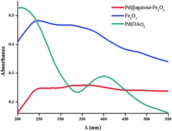
Fe3O4 nanoparticles were prepared without using any capping agent or surfactant via conventional co-precipitation of iron(II) chloride and iron(III) chloride according to a reported procedure.21 After sonication, Fe3O4 nanoparticles were treated with agarose in the presence of Pd(OAc)2 and citric acid as a reducing agent in aqueous media. After drying the resulting material, the initial investigation was focused on the characterization of the resulting new solid material. Based on the atomic absorption spectroscopy (AAS) analysis, the amount of Pd in Pd@agarose–Fe3O4 was found to be 0.0075 mmol Pd g−1.The solid UV-Vis spectrum of the obtained material shows complete conversion of Pd(II) to Pd(0) by the absence of the peak at 420 nm which belongs to Pd(II) species (Fig. 1). In addition, increase of the absorption in the visible region for the catalyst indicates that the Pd(0) nanoparticles are formed.22
The FT-IR spectrum of Pd@agarose–Fe3O4 did not show a carbonyl group absorption band, which confirms that the –OAc anion has been removed after the process of reduction of Pd(II) to Pd(0). The characteristic absorption bands of Fe3O4 nanoparticles at 630, 578 and 442 cm−1 are attributed to the presence of Fe–O bonds.23 These results prove the existence of magnetic Fe3O4 nanoparticles in the new solid material (see ESI†).
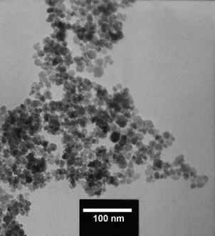
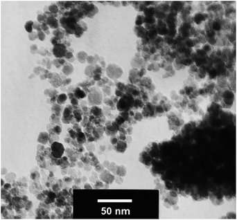
To get information about the size of metal particles distributed in the agarose mass, the TEM image of the material (Fig. 2) was studied. The image shows that the particles are mostly spherical and have an average diameter of about 10–15 nm. However, the amount of palladium NP on the surface of the material is very low and therefore, differentiation of Pd NP from Fe3O4 NP is not so easy.
The EDX study of Pd@agarose–Fe3O4 (see ESI†) confirms the presence of palladium and iron nanoparticles in the structure of the material.
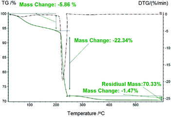
The thermo-gravimetric analysis (TGA) of Pd@agarose–Fe3O4 shows that the prepared composites have high thermal stability and negligible agarose leaching up to 200 °C (Fig. 3).
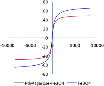
The superparamagnetic24 behavior of Pd@agarose–Fe3O4 was confirmed using magnetization curves of Fe3O4 NPs and Pd@agarose–Fe3O4 at room temperature (Fig. 4). The two samples show zero coercivity and remanence on the magnetization loop. The absence of a hysteresis loop shows the superparamagnetic property and the ability of the material to be separated from the reaction mixture by an external magnet (Fig. 5). In addition, the decrease in the magnetization value of the composite (65.8 emu g−1) in comparison with Fe3O4 NPs (48.7 emu g−1) confirms that the surface of Fe3O4 NPs is covered by the attachment of agarose molecules through their bond formation via their hydroxyl functional groups.
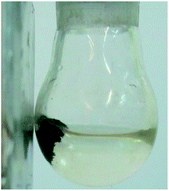 | ||
| Fig. 5 Photograph showing the magnetic separation of Pd@agarose–Fe3O4 catalyst from the PEG phase by an external magnet. | ||
After characterizing Pd@agarose–Fe3O4, we investigated the catalytic properties of Pd@agarose–Fe3O4 for C–C bond formation via a Suzuki–Miyaura coupling reaction. For this purpose, the reaction of 4-iodotoluene (1.0 mmol) with phenylboronic acid (1.5 mmol) as a model reaction in the presence of K2CO3 (1.5 mmol) and 20 mg of Pd@agarose–Fe3O4 (this optimized amount of the catalyst was found through a study as shown in Table 3 and contains 1.5 × 10⁻⁴ mmol of Pd as determined by ICP analysis) in different solvents at 80 °C was studied (Table 1). The results of this experiment showed that wet PEG 200 was the most suitable solvent for this reaction.
The effect of different bases was also studied using the reaction of 4-iodotoluene with phenylboronic acid. Among the studied bases, NaOH and K2CO3 were found to be suitable; however, K2CO3 was selected as the most efficient base for the reaction, as shown in Table 2.
The optimized reaction condition was then applied to the reaction of varieties of aryl halides with arylboronic acids. Aryl iodides were reacted efficiently with phenylboronic acid, 4-fluorophenylboronic acid and pinacol vinylboronate. The reactions proceeded smoothly to produce the desired biphenyl and phenylvinyl products in excellent yields. Also, the reactions of aryl bromides under the optimized conditions proceeded successfully to give the desired biphenyl and phenylvinyl products in high to excellent yields. However, under the optimized reaction conditions, the reactions of aryl chlorides proceeded sluggishly. Therefore, the temperature of the reaction was raised to 130 °C; at this temperature, the aryl chlorides reacted more efficiently and afforded the corresponding biphenyl and phenylvinyl products in 67–89% isolated yields (Table 4).
Along with the expansion of the application of the catalyst, the Heck–Mizoroki reaction was also studied under similar optimized reaction conditions as mentioned above. For this purpose, reactions of a variety of aryl halides with styrene, butyl acrylate and 1-octene in the presence of 20 mg of the catalyst and K2CO3 in PEG 200 at 80 °C were studied. However, the reactions of aryl bromides and chlorides with alkenes were found to be inefficient at 80 °C. Therefore, the reaction temperature was increased to 120 °C for aryl bromides and to 130 °C for aryl chlorides. The results show that the catalyst was suitable and efficient for Heck–Mizoroki reactions using structurally different aryl halides and alkenes to give the desired alkene compounds in good to excellent isolated yields (Table 5).
| Entry | ArX | Alkene | T (°C) | Time (h) | Product | Yield% |
|---|---|---|---|---|---|---|
| a In parentheses, time and the isolated yield of the large-scale reaction using 10 mmol of iodobenzene and 20 mmol of styrene are indicated. | ||||||
| 1 |  |
Styrene | 80 | 1(1)a |  |
94(89) |
| 2 |  |
Styrene | 80 | 4 |  |
92 |
| 3 |  |
Styrene | 80 | 1 |  |
94 |
| 4 |  |
Styrene | 80 | 18 |  |
67 |
| 5 |  |
Styrene | 120 | 20 |  |
20 |
| 6 |  |
Styrene | 120 | 14 |  |
93 |
| 7 |  |
Styrene | 120 | 16 |  |
87 |
| 8 |  |
Styrene | 120 | 20 |  |
85 |
| 9 |  |
Styrene | 130 | 24 |  |
87 |
| 10 |  |
Butyl acrylate | 80 | 1 |  |
94 |
| 11 |  |
Butyl acrylate | 80 | 1 |  |
94 |
| 12 |  |
Butyl acrylate | 80 | 1 |  |
92 |
| 13 |  |
Butyl acrylate | 120 | 14 |  |
60 |
| 14 |  |
Butyl acrylate | 120 | 10 |  |
88 |
| 15 |  |
Butyl acrylate | 130 | 24 |  |
76 |
The application of the catalyst was also extended to C–C bond formation via the Sonogashira–Hagihara reaction by studying the reaction of structurally different aryl iodides, bromides and chlorides with phenylacetylene. First, we performed optimization of the reaction conditions with respect to solvents, bases, temperature, and the amounts of the catalyst for the reaction of 4-iodotoluene (1.0 mmol) with phenylacetylene (1.5 mmol). These reactions were carried out using 10 mg of the catalyst in the presence of K2CO3 (2 mmol) in different solvents at 100 °C. The results showed that PEG 200 and K2CO3 were the most suitable solvent and the base for the reaction. Under these conditions, the yield of the product was found to be only 60%, even though the reaction was completed with respect to the reactants in the appropriate reaction time (Table 6, Entry 1). This observation induced us to study the effect of the amounts of the catalyst on the reaction. By increasing the amount of the catalyst from 10 to 30 mg, an increase in the byproduct formation was observed (Table 7, Entries 10 and 11). Thus the amount of the catalyst was kept at 10 mg. Then the effect of increasing the temperature was investigated. The results showed that increasing the temperature from 100 °C to 120 °C was accompanied with a decrease of the reaction time, but the amount of unwanted products increased (Table 6, Entries 13 and 14). Finally, we decided to increase the amount of K2CO3 from 2 mmol to 3 mmol in the presence of 10 mg of the catalyst in wet PEG 200. By this change, the desired product was obtained in 94% isolated yield (Table 6, Entry 17).
| Entry | Catalyst (g) | Solvent | Base | Temp. (°C) | Time (h) | Isolated yields (%) |
|---|---|---|---|---|---|---|
| a Conversion was 100% under the defined condition.b Reaction proceeded in the presence of 3 mmol of K2CO3. | ||||||
| 1 | 0.02 | PEG 200 | K2CO3 | 100 | 1 | 60a |
| 2 | 0.02 | PEG 200 | KOAc | 100 | 1 | 40 |
| 3 | 0.02 | PEG 200 | n-Pr3N | 100 | 1 | 10 |
| 4 | 0.02 | PEG 200 | None | 100 | 1.5 | N.R |
| 5 | 0.02 | DMSO | K2CO3 | 100 | 1 | 44 |
| 6 | 0.02 | EtOH | K2CO3 | 100 | 1 | 25 |
| 7 | 0.02 | NMP | K2CO3 | 100 | 1 | 50 |
| 8 | 0.02 | DMF | K2CO3 | 100 | 1 | 30 |
| 9 | 0.02 | EG | K2CO3 | 100 | 1 | 10 |
| 10 | 0.03 | PEG 200 | K2CO3 | 100 | 0.5 | 50 |
| 11 | 0.01 | PEG 200 | K2CO3 | 100 | 3 | 73 |
| 12 | None | PEG 200 | K2CO3 | 100 | 5 | 10 |
| 13 | 0.01 | PEG 200 | K2CO3 | 110 | 1.5 | 65 |
| 14 | 0.01 | PEG 200 | K2CO3 | 120 | 1 | 60 |
| 15 | 0.01 | PEG 200 | K2CO3/TBAB | 100 | 3 | 70 |
| 16 | 0.01 | None | K2CO3/TBAB | 100 | 1.5 | N.R |
| 17 | 0.01 | PEG 200 | K2CO3 | 100 | 1.5 | 94b |
Then the optimized reaction condition was applied to the reaction of structurally different halides with phenyl acetylene. The reaction of aryl iodides and bromides proceeded smoothly and the desired aryl alkynes were obtained in 60–95% isolated yields (Table 7, Entries 1–11). In the case of aryl chlorides, the reaction needed harsher conditions; therefore, the reaction temperature was raised to 130 °C. At this temperature, aryl chlorides did react and the corresponding aryl alkynes were obtained in 53–62% isolated yields (Table 7, Entries 12 and 13).
Finally, recycling of the catalyst was tested for the reaction of 4-iodotoluene with n-butyl acrylate employing 20 mg of the catalyst in the presence of K2CO3/PEG 200 at 80 °C. After completion of the reaction, the reaction mixture was diluted with ethyl acetate. The catalyst was separated by an external magnet (Fig. 5), washed with ethyl acetate, water and dried under vacuum. The resulting solid catalyst was used directly for the next run. The yield of the desired product dropped from 94% after the first run to 86% after the sixth run, which shows a negligible loss in activity of the catalyst (Table 8).
As shown in Table 8, no considerable change in the reaction yield was observed during six consecutive runs. This observation indicates that the amounts of leaching of Pd into the reaction mixture must not be significant; this has also been quantitatively supported by ICP analysis. The analysis showed that after six recycling runs of the catalyst, only 7% of Pd was leached.
The TEM image of the recycled catalyst shows that the catalyst preserves its structure with little aggregation of the nanoparticles after the second run (Fig. 6).
Conclusion
In this study, we have introduced a new magnetically separable material: Pd@agarose–Fe3O4. In this composite, palladium nanoparticles are supported on an agarose hydrogel which is attached to magnetic Fe3O4 nanoparticles. This new compound was characterized by different techniques, such as EDX, TEM, TGA, FT-IR, VSM, AAS, and solid UV-visible analysis. Pd@agarose–Fe3O4 shows good magnetic properties and has been successfully applied as a catalyst for Suzuki–Miyaura, Heck–Mizoroki and Sonogashira–Hagihara reactions of structurally different aryl halides in wet PEG 200. The recyling of the catalyst was successfully tested in the Heck–Mizoroki reaction for six consecutive runs. The TEM images of the recycled catalyst shows that agglomeration of the nanoparticles in the catalyst was negligible and that the size of the particles was reasonably preserved during the reaction. The ICP analysis of the reaction mixture shows that the amounts of the Pd species leached into the reaction mixture was not significant and after six consecutive runs in a Heck reaction, only 7% of Pd was leached into the reaction media.Experimental
All reactants were purchased from Acros, Merck and Sigma Aldrich and were used without further purification. 1H NMR spectra were recorded at 250 and 400 MHz, and 13CNMR spectra were recorded at 62.9 and 100 MHz in CDCl3 using TMS as an internal standard. Thin layer chromatography was carried out on silica gel 254 analytical sheets obtained from Fluka. Column chromatography was carried out on silica gel 60 Merck (230–240 mesh) in glass columns (2 or 3 cm diameter) using 15–30 grams of silica gel per one gram of the crude mixture. Thermo-gravimetric analysis was conducted from room temperature to 800 °C in an oxygen flow using a NETZSCH STA 409 PC/PG instrument. The structures of the prepared materials were observed by transmission electron microscopy (Philips CM-120). FT-IR spectra were obtained using a Shimadzu FTIR-8300 spectrophotometer. UV-Vis spectra were recorded on a Perkin Elmer Lambda 25, UV-Vis spectrometer.Gram-scale preparation of Pd@agarose–Fe3O4
Agarose (1.00 g) was dissolved in water (100 mL) and heated to 80 °C for 15 min. To this solution, the synthesized Fe3O4 nanoparticles (4.00 g), which had been sonicated in H2O (25 mL) for 15 min, were added. The resulting mixture was stirred for 4 h at 80 °C. Then an acidic solution of Pd(OAc)2 (0.022 g, 1.0 mM) was added. After that, a solution of citric acid (20 mL, 4.0 mM) was added and the mixture was stirred for 12 h at 80 °C. Upon stirring, a black gel mass of the hydrogel was formed, which was separated from the mixture by an external magnet. The resulting solid Pd@agarose–Fe3O4 was washed with cold water (3 × 15 mL) and ethanol (3 × 15 mL), and dried under vacuum to give Pd@agarose–Fe3O4 composite.General procedure for Suzuki–Miyaura reaction of aryl halides catalyzed by Pd@agarose–Fe3O4 in PEG 200
To a flask containing the catalyst (20 mg, containing 1.57 × 10⁻⁴ mmol of Pd species as determined by ICP analysis) in PEG 200 (2 mL), were added aryl halide (1.0 mmol), organoborane (1.5 mmol) and K2CO3 (2.0 mmol, 0.276 g), and the mixture was stirred at 80 °C for the appropriate reaction time. After completion of the reaction (monitored by GC or TLC), the catalyst was separated from the reaction mixture by an external magnet. Then H2O (10 mL) was added to the mixture and the product was extracted with ethyl acetate (3 × 10 mL). The organic extracts were combined and dried over anhydrous MgSO4. Evaporation of the solvent afforded the crude desired product, which was purified by column chromatography on silica gel using n-hexane or different mixtures of n-hexane–ethyl acetate as the eluents to afford the highly pure products in 80–97% yields (Table 4).General procedure for the Heck–Mizoroki reaction of aryl halides and styrene in the presence of Pd@agarose–Fe3O4 in PEG 200
Aryl halide (1.0 mmol) and alkene (2.0 mmol) were added to a flask containing the catalyst (20 mg, containing 1.57 × 10⁻⁴ mmol of Pd) and K2CO3 (2.0 mmol) in PEG 200 (2 mL). The mixture was stirred at appropriate temperature for the appropriate reaction time (Table 5). Progress of the reaction was monitored by GC or TLC. After completion of the reaction, the catalyst was separated by an external magnet. Then, H2O (10 mL) was added to the mixture and extracted with ethyl acetate (3 × 10 mL). The organic portions were combined and dried over anhydrous MgSO4 and filtered. The resulting solution was evaporated under vacuum to give the crude product. The column chromatography of the crude product on silica gel using n-hexane or different mixtures of n-hexane–ethyl acetate as the eluents afforded the highly pure product (Table 5).General procedure for Sonogashira–Hagihara reaction of aryl halides in the presence of Pd@agarose–Fe3O4 in PEG 200
A round-bottom flask was charged with phenylacetylene (1.5 mmol, 0.153 g), K2CO3 (3.0 mmol, 0.414 g), PEG 200 (2 mL), and aryl halide (1.0 mmol). To this mixture, the catalyst (10 mg, containing 0.78 × 10⁻⁴ mmol of Pd) was added. The mixture was stirred at 100 °C under an argon atmosphere; the progress of the reaction was monitored by GC or TLC. After completion of the reaction, the catalyst was removed by an external magnet. To the resulting mixture H2O (10 mL) was added followed by extraction with ethyl acetate (3 × 10 mL). The combined organic phases were dried over anhydrous MgSO4 and filtered. The organic solvent was evaporated under diminished pressure to give the desired crude product. Purification of the crude product was performed by column chromatography on silica using n-hexane or different mixtures of n-hexane–ethyl acetate as the eluents to afford the product in a high purity in 53–95% isolated yields (Table 7).Acknowledgements
The authors are thankful for the support of this work by grant number BN048 from the National Elite Foundation of Iran, Iran National Science Foundation (INSF-Grant number of 90007432), Institute for Advanced Studies in Basic Sciences (IASBS) Research Council and Shiraz University Research Council. M.G. is also thankful to Dr S. H. Kazemi and H. R. Shahsavari for SEM/EDX and solid UV-visible analysis.Notes and references
- B. C. G. Soderberg, Coord. Chem. Rev., 2003, 241, 147–247 CrossRef CAS.
- (a) F. Alonso, I. P. Beletskaya and M. Yus, Tetrahedron, 2008, 64, 3047–3101 CrossRef CAS PubMed; (b) F.-S. Han, Chem. Soc. Rev., 2013, 42, 5270 RSC; (c) V. Polshettiwar, A. Decottignies, C. Len and A. Fihri, ChemSusChem, 2010, 3, 502 CrossRef CAS PubMed; (d) S. Kotha, K. Lahiri and D. Kashinath, Tetrahedron, 2002, 58, 9633 CrossRef CAS.
- (a) A. M. Trzeciak and J. J. Ziołkowski, Coord. Chem. Rev., 2007, 251, 1281 CrossRef CAS PubMed; (b) V. Polshettiwar and A. Molnar, Tetrahedron, 2007, 63, 6949 CrossRef CAS PubMed; (c) V. Farina, Adv. Synth. Catal., 2004, 346, 1553 CrossRef CAS PubMed.
- (a) K. Sonogashira, in Metal Catalyzed Cross-Coupling Reactions, ed. F. Diederich and A. de Meijera, Wiley-VCH, Weinheim, 2004 Search PubMed; (b) R. R. Tykwinski, Angew. Chem., Int. Ed., 2003, 42, 1566 CrossRef CAS PubMed; (c) E. Negishi and L. Anastasia, Chem. Rev., 2003, 103, 1979 CrossRef CAS PubMed; (d) K. Sonogashira, in Handbook of Organopalladium Chemistry for Organic Synthesis, ed. E. Negishi and A. de Meijere, Wiley-Interscience, New York, 2002 Search PubMed; (e) K. Sonogashira, J. Organomet. Chem., 2002, 653, 46 CrossRef CAS; (f) R. Rossi, A. Carpita and F. Bellina, Org. Prep. Proced. Int., 1995, 27, 127 CrossRef CAS; (g) K. Sonogashira, in Comprehensive Organic Synthesis, ed. B. M. Trost and I. Fleming, Pergamon, Oxford, 1991, pp. 521–561 Search PubMed; (h) R. Chinchilla and C. Najera, Chem. Rev., 2007, 107, 874 CrossRef CAS PubMed.
- (a) M. Lamblin, L. N. Hardy, J.-C. Hierso, E. Fouquet and F.-X. Felpin, Adv. Synth. Catal., 2010, 352, 33 CrossRef CAS PubMed; (b) N. T. S. Phan, M. Van Der Sluys and C. W. Jones, Adv. Synth. Catal., 2006, 348, 609 CrossRef CAS PubMed.
- (a) C. W. Lim and I. S. Lee, Nano Today, 2010, 5, 412 CrossRef CAS PubMed; (b) R. B. Nasir Baig and R. S. Varma, Green Chem., 2013, 15, 398 RSC; (c) S. Shylesh, V. Schnemann and W. R. Thiel, Angew. Chem., Int. Ed., 2010, 49, 3428 CrossRef CAS PubMed.
- (a) B. Baruwati, D. Guin and S. V. Manorama, Org. Lett., 2007, 9, 5377 CrossRef CAS PubMed; (b) Z. Yinghuai, S. C. Peng, A. Emi, S. Zhenshun, R. Monalisa and R. A. Kemp, Adv. Synth. Catal., 2007, 349, 1917 CrossRef PubMed; (c) J. Hu, Y. Wang, M. Han, Y. Zhou, X. Jiang and P. Sun, Catal. Sci. Technol., 2012, 2, 2332 RSC; (d) Z. Wang, B. Shen, Z. Aihua and N. He, Chem. Eng. J., 2005, 113, 27 CrossRef CAS PubMed; (e) P. D. Stevens, G. Li, J. Fan, M. Yen and Y. Gao, Chem. Commun., 2005, 4435 RSC; (f) J. Liu, X. Peng, W. Sun, Y. Zhao and C. Xia, Org. Lett., 2008, 10, 3933 CrossRef CAS PubMed; (g) D. Rosario-Amorin, M. Gaboyard, R. Clerac, L. Vellutini, S. Nlate and K. Heuze, Chem.–Eur. J., 2012, 18, 3305 CrossRef CAS PubMed; (h) Q. Zhang, H. Su, J. Luo and Y. Wei, Catal. Sci. Technol., 2013, 3, 235 RSC; (i) H. Yang, G. Li and Z. Ma, J. Mater. Chem., 2012, 22, 6639–6648 RSC; (j) J. Wang, B. Xu, H. Sun and G. Song, Tetrahedron Lett., 2013, 54, 238 CrossRef CAS PubMed; (k) P. Li, L. Wang, L. Zhang and G.-W. Wang, Adv. Synth. Catal., 2012, 354, 1307 CrossRef CAS PubMed; (l) J.-R. Niu, X. Huo, F.-W. Zhang, H.-B. Wang, P. Zhao, W.-Q. Hu, J. Ma and R. Li, ChemCatChem, 2013, 5, 349 CrossRef CAS PubMed.
- (a) M. J. Aliaga, D. J. Ramon and M. Yus, Org. Biomol. Chem., 2010, 8, 43 RSC; (b) F. Nador, M. A. Volpe, F. Alonso, A. Feldhoff, A. Kirschning and G. Radivoy, Appl. Catal., A, 2013, 455, 39 CrossRef CAS PubMed; (c) T. Zeng, L. Yang, R. Hudson, G. Song, A. R. Moores and C. J. Li, Org. Lett., 2011, 13, 442 CrossRef CAS PubMed.
- H.-J. Yoon, J.-W. Choi, H. Kang, T. Kang, S.-M. Lee, B.-H. Jun and Y.-S. Lee, Synlett, 2010, 2518 CAS.
- (a) Y.-M. Zhou, H.-B. Wang, M. Gong, Z.-Y. Sun, K. Cheng, X.-k. Kong, Z. Guo and Q.-W. Chen, Dalton Trans., 2013, 42, 9906 RSC; (b) J. Hu, Y.-l. Dong, X.-j. Chen, H.-j. Zhang, J.-m. Zheng, Q. Wang and X.-g. Chen, Chem. Eng. J., 2014, 236, 1 CrossRef CAS PubMed; (c) F. G. de Rivera, I. Angurell, M. D. Rossell, R. Erni, J. Llorca, N. J. Divins, G. Muller, M. Seco and O. Rossell, Chem.–Eur. J., 2013, 19, 11963 CrossRef PubMed.
- (a) J. Liu, X. Peng, W. Sun, Y. Zhao and C. Xia, Org. Lett., 2008, 10, 3933 CrossRef CAS PubMed; (b) M. S. Kwon, I. S. Park, J. S. Jang, J. S. Lee and J. Park, Org. Lett., 2007, 9, 3417 CrossRef CAS PubMed; (c) H. Yoon, S. Ko and J. Jang, Chem. Commun., 2007, 1468 RSC; (d) K. Mori, S. Kanai, T. Hara, T. Mizugaki, K. Ebitani, K. Jitsukawa and K. Kaneda, Chem. Mater., 2007, 19, 1249 CrossRef CAS; (e) X. Teng, D. Black, N. J. Watkins, Y. Gao and H. Yang, Nano Lett., 2003, 3, 261 CrossRef CAS; (f) M. Shokouhimehr, Y. Piao, J. Kim, Y. Jang and T. Hyeon, Angew. Chem., 2007, 119, 7169 (Angew. Chem., Int. Ed., 2007, 46, 7039) CrossRef PubMed; (g) T. Zeng, W.-W. Chen, C. M. Cirtiu, A. Moores, G. Song and C.-J. Li, Green Chem., 2010, 12, 570 RSC.
- (a) S. Luo, X. Zheng, H. Xu, X. Mi, L. Zhang and J.-P. Cheng, Adv. Synth. Catal., 2007, 349, 2431 CrossRef CAS PubMed; (b) R. Abu-Reziq, D. Wang, M. Post and H. Alper, Adv. Synth. Catal., 2007, 349, 2145 CrossRef CAS PubMed; (c) M. Kawamura and K. Sato, Chem. Commun., 2006, 4718 RSC; (d) S. Ding, Y. Xing, M. Radosz and Y. Shen, Macromolecules, 2006, 39, 6399 CrossRef CAS; (e) N. T. S. Phan and C. W. Jones, J. Mol. Catal. A: Chem., 2006, 253, 123 CrossRef CAS PubMed; (f) P. D. Stevens, G. Li, J. Fan, M. Yen and Y. Gao, Chem. Commun., 2005, 4435 RSC; (g) R. De Palma, S. Peeters, M. J. Van Bael, H. Van den Rul, K. Bonroy, W. Laureyn, J. Mullens, G. Borghs and G. Maes, Chem. Mater., 2007, 19, 1821 CrossRef CAS; (h) S. Luo, X. Zheng and J.-P. Cheng, Chem. Commun., 2008, 5719 RSC.
- (a) L. M. Rossi, L. L. R. Vono, F. P. Silva, P. K. Kiyohara, E. L. Duarte and J. R. Matos, Appl. Catal., A, 2007, 330, 139 CrossRef CAS PubMed; (b) T. J. Yoon, W. Lee, Y.-S. Oh and J.-K. Lee, New J. Chem., 2003, 27, 227 RSC; (c) T. J. Yoon, J. I. Kim and J.-K. Lee, Inorg. Chim. Acta, 2003, 345, 228 CrossRef CAS.
- (a) A. Hu, G. T. Yee and W. Lin, J. Am. Chem. Soc., 2005, 127, 12486 CrossRef CAS PubMed; (b) G. Chouhan, D. Wang and H. Alper, Chem. Commun., 2007, 4809 RSC; (c) Y. Zheng, C. Duanmu and Y. Gao, Org. Lett., 2006, 8, 3215 CrossRef CAS PubMed.
- (a) C. R. Vestal and J. Zhang, J. Am. Chem. Soc., 2002, 124, 14312–14313 CrossRef CAS PubMed; (b) S. Yu and M. Chow, J. Mater. Chem., 2004, 14, 2781 RSC; (c) C. Mangeney, M. Fertani, S. Bousalem, M. Zhicai, S. Ammar, F. Herbst, P. Beaunier, A. Elaissari and M. M. Chehimi, Langmuir, 2007, 23, 10940 CrossRef CAS PubMed; (d) K. M. Ho and P. Li, Langmuir, 2008, 24, 1801 CrossRef CAS PubMed; (e) A. Schaetz, M. Zeltner, T. D. Michl, M. Rossier, R. Fuhrer and W. J. Stark, Chem.–Eur. J., 2011, 17, 10566 CrossRef CAS PubMed; (f) F. Caruso, M. Spasova, A. Susha, M. Giersig and R. A. Caruso, Chem. Mater., 2001, 13, 109 CrossRef CAS; (g) A. P. Philipse, M. P. B. van Bruggen and C. Pathmamanoharan, Langmuir, 1994, 10, 92 CrossRef CAS.
- S. J. Zhang, X. Y. Li and J. P. Chen, Carbon, 2010, 48, 60 CrossRef CAS PubMed.
- D. Yang, F. Yang, J. H. Hu, J. Long, C. C. Wang, D. L. Fu and Q. X. Ni, Chem. Commun., 2009, 4447–4449 RSC.
- (a) X. Y. Yang, X. Y. Zhang, Y. F. Ma, Y. Huang, Y. S. Wang and Y. S. Chen, J. Mater. Chem., 2009, 19, 2710 RSC; (b) H. P. Cong, J. J. He, Y. Lu and S. H. Yu, Small, 2009, 6, 169 CrossRef PubMed.
- (a) H. Firouzabadi, N. Iranpoor and F. Kazemi, J. Mol. Catal. A: Chem., 2011, 348, 94 CrossRef CAS PubMed; (b) H. Firouzabadi, N. Iranpoor, M. Gholinejad and F. Kazemi, RSC Adv., 2011, 1, 1013 RSC; (c) H. Firouzabadi, N. Iranpoor, F. Kazemi and M. Gholinejad, J. Mol. Catal. A: Chem., 2012, 357, 154 CrossRef CAS PubMed.
- A. Kong, P. Wang, H. Zhang, F. Yang, S. P. Huang and Y. Shan, Appl. Catal., A, 2012, 417–418, 183 CrossRef CAS PubMed.
- H. Firouzabadi, N. Iranpoor, M. Gholinejad and J. Hoseini, Adv. Synth. Catal., 2010, 352, 119 CrossRef CAS PubMed.
- (a) Y. Li, X. M. Hong, D. M. Collard and M. A. El-Sayed, Org. Lett., 2000, 2, 2385 CrossRef CAS PubMed; (b) B. M. Choudary, S. Madhi, N. S. Chowdari, M. L. Kantam and B. Sreedhar, J. Am. Chem. Soc., 2002, 124, 14127–14136 CrossRef CAS PubMed.
- J. Zhang, S. Rana, R. S. Srivastava and R. D. K. Misra, Acta Biomater., 2008, 4, 40 CrossRef CAS PubMed.
- H. Mahmoudi and A. A. Jafari, ChemCatChem, 2013, 5, 3743 CrossRef CAS PubMed.
Footnote |
| † Electronic supplementary information (ESI) available. See DOI: 10.1039/c4ra00900b |
| This journal is © The Royal Society of Chemistry 2014 |

