Self-assembled ultra-small zinc stannate nanocrystals with mesoscopic voids via a salicylate templating pathway and their photocatalytic properties

Vandana Kumari, Astam K. Patra and Asim Bhaumik*
Department of Materials Science, Indian Association for the Cultivation of Science, Jadavpur, Kolkata-700 032, India. E-mail: msab@iacs.res.in

Received 10th January 2014 , Accepted 27th January 2014

First published on 29th January 2014


Abstract

Self-assembled, tiny zinc stannate nanocrystals with controlled crystalline phases of ZnSnO3 (MZS-1) and Zn2SnO4 (MZS-2) together with mesoscopic void spaces have been synthesized via a salicylate templating method with particle dimensions of ca. 1–2 nm and 17–20 nm for MZS-1 and 2, respectively. These nanomaterials have been thoroughly characterized by powder XRD, HR TEM, N2-sorption, TG-DTA and UV-visible spectroscopic tools. Self-aggregation of the tiny nanoparticles could be responsible for these interparticle mesopores in these zinc stannate nanocrystals. The Zn2SnO4 nanomaterial showed higher photocatalytic activity over that of ZnSnO3 in the photodegradation of Rhodamine B under the irradiation of UV/visible light.

Introduction

The design and successful synthesis of ultra small semiconductor nanocrystals with controlled shape, size and their organized nanostructures through bottom-up chemistry approaches have long been an intensive and interdisciplinary area of research.1 Along with quantum size effects, surface effects attain greater significance when the size of the nanocrystals is decreased to few nanometers because this results in a rapid increase in the surface-to-volume ratio. Convenient syntheses of the nanocrystals through different synthetic and physical routes,2 large diversity in chemical compositions and novel properties of these nanocrystals have made them an extremely active area of research for the last two decades, especially in optoelectronics,3 sensing,4 biomolecular separation,5 drug delivery6 and photocatalysis.7 Often the self-assembly of these nanoparticles could be achieved in the presence of small functional organic molecules or templates, which could act as a capping agent to stabilize the particular nanostructures.8 This capping agent plays crucial role in directing the organized nanostructures through the self-aggregation of superstructures in the solution phase.9 Although there are several strategies known for designing self-assembled metal oxide nanoparticles,10 the synthesis of highly crystalline and tiny, binary semiconducting, mixed metal oxide nanocrystals together with nanoscale porosity is still a big challenge today.

Recently, researchers have focused a great deal of attention on the synthesis of self-assembled nanoparticles of CeO2,11 ZrO2,12 SnO2,13 Fe3O4,14 ZnO,15 etc. having interparticle voids. There are few reports of on the synthesis of ZnSnO3 and Zn2SnO4 nanoparticles and their gas-sensing and photocatalytic properties.16,17 Fan et al. have synthesized nanocrystalline hollow ZnSnO3 microspheres by a hydrothermal method, which showed good sensing for hydrocarbons like butane.18 Self-assembly through non-covalent interactions, like H-bonding interactions,19 π–π interactions,20 etc. is a versatile technique for the synthesis of different ultra-small nanostructured materials. Zhou et al. have synthesized very small TiO2 nanoparticles at room temperature and these nanoparticles are self-assembled toward mesoporous spherical aggregates in presence of ionic liquids.21 Oxide-based nanomaterials with particle sizes ranging from 1–10 nm can absorb larger numbers of photons at their surface due their higher surface-to-volume ratio and quantum size effects vis-à-vis the corresponding bulk materials.22 Thus, to design self-assembled zinc stannate nanoparticles with a controllable particle size and interparticle void space using a suitable capping agent is challenging as it can open new opportunities in optoelectronics,23 and environmental remediation via photocatalysis.24


image file: c4ra00251b-s1.tif
Scheme 1 Proposed chemical reactions during the synthesis of ZnSnO3 and Zn2SnO4 nanoparticles.

Environmental pollution caused by industrial effluents is one of the major concerns to life today. The textile and other related chemical industries release several organic dyes and this is one of the major reasons for water pollution.25 Thus, photocatalytic degradation of water pollutant organic dyes over porous zinc stannate nanomaterials can provide new insight to existing dye degradation strategies.26 Herein, we report the self-assembly of very tiny zinc stannate nanocrystals with a mesoscopic void space via a salicylate templating method depending upon various synthesis conditions. Particle size, surface area and related surface properties associated with the nanostructure plays a crucial role in optical and photocatalytic performance of these materials. These nanomaterials have been characterized thoroughly and their catalytic role in the photodegradation of organic dyes in the presence of visible and UV light has been explored.

Experimental

Chemicals

Sodium salicylate (GR 99.5%), used as the structure-directing agent, anhydrous zinc chloride (98%) and diethylamine (99.5%, used to maintain the pH of the synthesis gel) were purchased from Merck, India. Tin chloride pentahydrate (98%) was obtained from Loba Chemie, India. All chemicals were used without any further purification.

Hydrothermal synthesis of zinc stannate (ZnSnO3 and Zn2SnO4) nanoparticles

Zinc stannate (ZnSnO3 and Zn2SnO4) nanomaterials were synthesized via a hydrothermal route by using sodium salicylate as a template. In a typical synthesis 1.6 g (0.01 mol) of sodium salicylate was dissolved into 20 ml distilled water and 1 ml of diethylamine was added to this solution. Then the resultant solution was stirred for 30 min. Then 0.525 g (0.0038 mol) of the Zn(II) precursor, anhydrous ZnCl2 and 0.675 g (0.0019 mol) of the Sn precursor, SnCl4·5H2O was dissolved into 5 ml of distilled water separately and mixed together under stirring conditions. The synthesis gel was prepared by adding the former template solution to the mixture of the acidic metal salt solution and the pH of the solution was raised up to 6.0 by adding additional diethylamine. Then the reaction mixture was stirred for 3 h and transferred in to a Teflon-lined stainless steel autoclave and hydrothermally treated at different temperatures, at 348, 373, 393, 423 and 448 K for 48 h. After the reaction, the autoclaves were cooled down to room temperature. The solids were collected through filtration, washed with deionized water for 3 times to remove the residual contaminant ions from the products and dried at room temperature. The sample synthesized at 348 K is designated as MZS-1 and that collected through hydrothermal treatment at 448 K followed by calcination at 773 K is abbreviated as MZS-2.

Characterization techniques

Powder X-ray diffraction patterns of both as-synthesized and calcined samples were recorded on a Bruker D8 Advance SWAX diffractometer operated at 40 kV voltage and 40 mA current. The instrument was calibrated with a standard silicon sample, using Ni-filtered Cu Kα (λ = 0.15406 nm) radiation. A JEOL JEM 2010 transmission electron microscope operated at an accelerating voltage ranging from 100 kV to 200 kV was employed for the determination of thr nanostructure and pore size. Nitrogen adsorption–desorption isotherms were obtained by using a Quantachrome Autosorb 1C surface area analyzer at 77 K. Prior to gas adsorption, samples were degassed for 4 h at 393 K under high vacuum. Thermogravimetric (TGA) and differential thermal analysis (DTA) of the samples were carried out in a TA Instruments thermal analyzer TA-SDT Q-600 under air flow. FT IR spectra of the samples were recorded using a Nicolet MAGNA FT IR 750 spectrometer Series II. UV-visible diffuse reflectance spectra were recorded on a Shimadzu UV 2401PC coupled with an integrating sphere attachment. BaSO4 was used as background standard.

Photocatalysis

The photocatalytic activity of porous zinc stannate (ZnSnO3 and Zn2SnO4) nanomaterials was studied in the photodegradation of Rhodamine B by using different concentrations of dye solution in water (20 mg l−1, 10 mg l−1 and 5 mg l−1). Photodegradation kinetics were carried out with a photocatalytic reactor system in the presence of both UV (wavelength 250–390 nm) as well as under visible light (400 to 800 nm) irradiation. For the UV source a 450 W medium-pressure Hg-vapor lamp (Hanovia) was placed inside the quartz tube. The lamp and the tube were immersed in the photoreactor cell, which was made of Pyrex glass. The temperature of the whole reactor was maintained at 298 K by using cold-water circulation to control the heat generated from the mercury-vapor lamp. The suspension was prepared by using 0.05 g photocatalyst in 10 ml dye solution (of different concentrations, such as 20 mg l−1, 10 mg l−1 and 5 mg l−1). Before photoirradiation, with either visible or UV light, the reactant solution with catalyst was stirred for 20 min in the dark to establish the adsorption–desorption equilibrium. The reactant solution was placed under light irradiation in the reactor and stirred magnetically to keep the suspension homogeneous. Then, at regular intervals of time (20 min) about 1 ml of the reactant solution was withdrawn and centrifuged to remove the catalyst. The residual dye concentration was calculated from the absorbance values measured at 553 nm using the UV 2401PC UV-visible spectrophotometer in the solution phase.

Results and discussion

Powder X-ray diffraction

The small angle powder X-ray diffraction pattern of the as-synthesized MZS-1 is shown in Fig. 1. A single broad peak for the mesophase with a peak maximum at 2θ = 1.48° could be attributed to the self-assembly of zinc stannate nanoparticles.27 The average distance between the nanoparticles corresponding to this small angle diffraction is 5.9 nm, which suggests that MZS-1 is composed of very tiny self-assembled nanoparticles and this is responsible for the formation of the mesophase. On the other hand, samples synthesized at higher temperature did not show this mesophase, as the particle growth predominates at higher temperature leads to large zinc stannate nanoparticles. The wide-angle X-ray diffraction patterns of MZS-1 and MZS-2, two zinc stannate samples synthesized at different temperatures, are shown in Fig. 2. These PXRD patterns revealed that the material MZS-1, prepared at 348 K, is made up of a purely face-centered cubic perovskite ZnSnO3 phase (JCPDS no. 11-0274), whereas the sample MZS-2, prepared at a comparatively higher temperature (448 K), is made up of face-centered cubic Zn2SnO4 crystallites (JCPDS no. 00-024-1470).28 Further, increasing the hydrothermal synthesis temperature causes the perovskite ZnSnO3 phase to convert into Zn2SnO4, and at 423 K both phases (ZnSnO3 and Zn2SnO4) are present simultaneously. Below this temperature no Zn2SnO4 phase is observed; at 348, 373 and 393 K only the pure face-centered cubic perovskite phase of ZnSnO3 has been observed and this was confirmed from the wide angle PXRD pattern of the materials. This is observed from the electron microscopic analysis also (see below). The X-ray diffraction peaks of the samples were compared with the JCPDS files of pure SnO2 and ZnO nanomaterials. Absence of any X-ray diffraction peaks from these probable impurity phases suggested that both zinc stannate nanomaterials synthesized through the salicylate templating pathway are highly stable and have pure phases of the corresponding nanocrystallites.
image file: c4ra00251b-f1.tif
Fig. 1 Small angle XRD patterns of the as-synthesized material MZS-1.

image file: c4ra00251b-f2.tif
Fig. 2 Wide angle XRD patterns of the as-synthesized material at different temperatures: 348 (MZS-1), 373, 393, 423 and 448 K (MZS-2, calcined).

Electron microscopic analysis

The representative TEM images of mesoporous zinc stannate nanomaterials (MZS-1 and MZS-2) are shown in Fig. 3. The HR TEM analysis of MZS-1 revealed that the material is composed of very tiny spherical nanoparticles of dimensions ca. 1–2 nm (Fig. 3b) and the white spots throughout the specimens of MZS-1 with average dimensions of ca. 1.9–2.7 nm (Fig. 3a) are quite clear. These self-aggregated nanoparticles could be responsible for these interparticle voids and mesopores. The crystal structure of the mixed oxides depend on the hydrothermal temperature; at 348 K the crystal phase of the material has been designated as ZnSnO3 with a spherical morphology, at 423 K the material is composed of a mixture of spherical ZnSnO3 and cubic Zn2SnO4 nanoparticles (Fig. 3c) and finally at 453 K the pure Zn2SnO4 cubic phase has been observed. The HR TEM analysis of MZS-2 has been shown in Fig. 3d. The material is composed of cubic crystalline nanoparticles with clear crystal edges of dimensions 17–20 nm. (Fig. 3e) The (111) lattice plane of the Zn2SnO4 material is quite prominent in the TEM image. (Fig. 3e) With increasing the particle size of the materials the tendency for self-aggregation decreases gradually, which is observable from the electron microscopic analysis of the material. The lattice fringes in the HR TEM image of the material MZS-2 suggest the high crystallinity of the material. The distance between the two crystal planes (Fig. 3f) is in quite good agreement with the d spacing of the (111) crystal plane of cubic crystal structure with a unit cell parameter a = 8.65 Å (JCPDS no. 241470). The corresponding SAED pattern of the MZS-2 material is shown in Fig. 4. Thus, while keeping the molar ratio of Zn/Sn constant in the synthesis gel it is possible to achieve temperature-induced crystal phase transformation in our newly developed zinc stannate synthesis pathway in the presence of sodium salicylate as the capping agent.
image file: c4ra00251b-f3.tif
Fig. 3 HR TEM images of self-assembled zinc stannate nanoparticles (a–e) and lattice fringes pattern for the material MZS-2 (f).

image file: c4ra00251b-f4.tif
Fig. 4 The SAED of the material MZS-2.

Porosity and surface area analysis

The Brunauer–Emmett–Teller (BET) surface area and porosity of the mesoporous materials are estimated from the N2 adsorption–desorption isotherms of the samples at 77 K. The adsorption–desorption isotherms for the samples MZS-1 and MZS-2 are shown in Fig. 5 (top and bottom). The BET surface area of the sample MZS-1 is 117 m2 g−1 and the isotherm can be classified as typical type I having supermicroporosity along with mesoporosity. The BET surface area for the sample MZS-2 is 60 m2 g−1 and this isotherm is typical type IV with an H3 type hysteresis loop which is characteristic for mesoporous materials.29 Their respective pore volumes are 0.0692 and 0.1404 cc g−1. The corresponding pore size distribution of these samples estimated by employing the non-local density functional theory (NLDFT)30 model is shown in the insets of Fig. 5. The estimated pore dimensions for the sample MZS-1 are 1.95 and 2.7 nm, suggesting that the material contains the pore in the supermicropore-to-mesopore region. On the other hand the average pore dimension for the sample MZS-2 varies from 5.6 to 6.9 nm. The t-method micropore analysis revealed the fact that MZS-1 contains an internal micropore area of 96 m2 g−1 with a micropore volume of 0.0432 cc g−1 together with considerable interparticle mesopores.31
image file: c4ra00251b-f5.tif
Fig. 5 N2 adsorption (●)–desorption (○) isotherms of the as-synthesized material MZS-1 (top) and MZS-2 (bottom) at 77 K. Corresponding NLDFT pore size distributions are shown in the inset.

Thermal stability of zinc stannate mesophases

The thermal stability of zinc stannate nanoparticles has been estimated from the TG-DTA profile of the samples under air flow with a heating rate of 10 °C min−1. The TG-DTA profile of MZS-1 is shown in Fig. 6. The TG-DTA plot shows three distinct weight losses. The first 10.20 wt% endothermic weight loss up to 464 K could be attributed to the loss of surface-adsorbed water molecules along with the partial burning of organic moieties in the self-assembled porous architecture. Further, a 9.83 wt% weight loss with a maximum at 641 K is assigned to the complete removal of organic moieties from the zinc stannate mesostructure. This is followed by a sharp exothermic peak corresponding to the internal phase transformation from the crystalline ZnSnO3 to amorphous nonporous material. The third weight loss at 964 K is attributed to the further phase transformation from the amorphous material to a mixture of Zn2SnO4 and SnO2 phases. On the other hand, the crystal phase of the sample MZS-2 is stable above 1000 K after heat-treatment in air. These TGA results indicate that Zn2SnO4 is thermally more stable than ZnSnO3.32
image file: c4ra00251b-f6.tif
Fig. 6 TG-DTA profile of the as-synthesized material MZS-1.

UV-visible spectra and band gaps of the nanomaterials

The optical property of the zinc stannate nanomaterials is studied through the UV-visible diffuse reflectance spectroscopy. The UV-visible reflectance spectra of the as-synthesized porous samples MZS-1 and -2 are shown in Fig. 7 and 8, respectively. MZS-1 shows an absorption maxima at 314 nm and this is extended up to 398 nm, whereas MZS-2 shows an absorption maxima at 260 nm and this is extended up to 399 nm. In both cases, the presence of extended absorption tails suggests the chemical binding of the salicylate molecules at the zinc stannate surface. The bandgap energies of as-synthesized MZS-1 is 3.41 eV, whereas that of template-free MZS-2 is 3.27 eV. The bandgap energy of as-synthesized MZS-2 is 3.59 eV. After heat treatment on Zn2SnO4 the absorption maxima is considerably red-shifted to 292 nm and the corresponding bandgap energy is 3.27 eV due to the incorporation of excess Zn into the zinc stannate nanocrystals.28,33 The reported bandgap energy for ZnSnO3 is little high (3.9 eV).34 Thus, in order to enhance its visible light induced photocatalytic activity, we have introduced a π-conjugated system (salicylate molecules), which could cap the nanoparticles and thus reduce the energy gap between the HOMO and LUMO in the MZS-1/2 composites compared to bulk zinc stannate. This is reflected in the corresponding UV-vis reflectance spectrum and respective decrease in bandgap energy.35
image file: c4ra00251b-f7.tif
Fig. 7 UV-visible diffuse reflectance spectrum of MZS-1. The bandgap of the material is shown in the inset.

image file: c4ra00251b-f8.tif
Fig. 8 UV-visible diffuse reflectance spectrum for MZS-2. The bandgap of the material is shown in the inset.

Temperature induced phase transformation

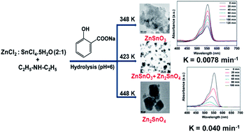
The temperature is a crucial parameter for the hydrothermal synthesis of different nanostructured materials.36 Here we have varied the synthesis temperature to get the most stable zinc stannate mesostructured materials with good surface area. The reactions are carried out at 348, 373, 393, 423 and 448 K, while other synthetic parameters are kept unchanged. When the synthesis temperatures are relatively low at 348–393 K, a pure ZnSnO3 phase is formed; as the synthesis temperature is increased to 423 K the mixture of both phases (ZnSnO3 and Zn2SnO4) is observed. At a further higher temperature of 448 K, pure Zn2SnO4 is formed exclusively. This result suggested that with increasing synthesis temperature ZnSnO3 phase-transforms into the Zn2SnO4 phase and the particle size also is increased from 1–2 nm to 17–20 nm.37 In this process first a rapid mixing of the metal salt led to the formation of colloid particles which appeared immediately in solution. This is due to the complex formation of ZnSn(OH)6 which is insoluble in water, and excess Zn2+ reacts with OH and produces the Zn(OH)42− phase, which is soluble in water. Under hydrothermal conditions, when the temperature is low (348, 373, 393 K) the ZnSn(OH)6 formed as an unstable intermediate is transformed into crystallite nanoparticles of the ZnSnO3 phase and excess Zn2+ could wash out from the gel in the form of Zn(OH)42− during filtration after the reaction. When the hydrothermal temperature increases up to 423 K some nuclei of ZnSn(OH)6 could react with the Zn(OH)42−, forming Zn2SnO4 and some nuclei of ZnSn(OH)6 were direct-transformed into ZnSnO3 nanocrystals. At 448 K all nuclei of ZnSn(OH)6 react with Zn(OH)42−, to form the pure Zn2SnO4 phase (Scheme 1).38 The SDA molecule sodium salicylate plays a crucial role in the formation of the mesophase and porosity. Zinc stannate nanoparticles bear considerable positive charge at their surface so they can interact with the negatively charged carboxylate groups of sodium salicylate molecules via electrostatic interaction. In the ligated salicylate moieties, hydrogen bonding and hydrophobic interactions occur due to the presence of an ortho phenolic –OH group in the sodium salicylate and these interactions help to form supramolecular assembly under synthesis conditions (Scheme 2).39 The synthesis temperature also plays a crucial role in stabilizing the organized self-assembled mesophase. A low synthesis temperature is more favorable for the formation of organized self-assemblies leading to a mesophase rather than a higher temperature. It is probably due to this reason only that at 348 K the self-assembled zinc stannate mesostructure is observed.40
image file: c4ra00251b-s2.tif
Scheme 2 Role of synthesis temperatures on the particle morphology and self-assembled nanostructures of zinc stannate.

Photocatalytic degradation of Rhodamine B

The photocatalytic activity of the as-prepared material MZS-1 and MZS-2 for the degradation of Rhodamine B dye (RhB) under UV and visible light irradiation is shown in Fig. 9. Rhodamine B shows the strongest absorption peak at 553 nm. The bandgap and surface area of the semiconductor nanocrystal plays an important role in the degradation of the organic dye molecule.41 The dye degradation capacity of the material MZS-1 (ZnSnO3) and MZS-2 (Zn2SnO4) for 5 mg l−1 RhB solution under UV light irradiation is shown in Fig. 9a and b and the corresponding result for MZS-2 (Zn2SnO4) with the same concentration of dye solution under visible light is shown in Fig. 9c. The lower bandgap of the materials is responsible for the high photocatalytic activity under visible/UV light. Due to this reason, the material MZS-2 (3.27 eV) shows better photocatalytic properties than the material MZS-1 (3.41 eV) under UV as well as visible light irradiation. The surface area and mesoporous architecture enhances the opportunity for the organic dyes to penetrate into the inside the pores and come into direct contact with the nanoparticle surface and thus more dye molecules can degrade.42 In the case of visible-light driven photocatalytic degradation of dye by binary semiconducting metal oxide nanocrystals, the dye sensitization mechanism is considered to be the most crucial (Scheme 3a).43 As the injection of electron from the conduction band of dye molecule to the LUMO of semiconductor material is a prime criterion for dye degradation under visible light, a direct contact between the organic dye molecule and the semiconductor material is essential.44 So, inorganic semiconductor porous nanomaterials with a high surface area are responsible for higher dye degradation rates under visible light.45 In our case, the surface area of the MZS-1 is higher than MZS-2 but the material MZS-1 bears salicylate molecules with an organic moiety. Hence due to the more energetically favorable π–π stacking interaction, the chromophore molecules are absorbed to a higher degree in the organic part of the MZS-1 material; so the contact between the active catalytic site and dye molecule decreases significantly. Thus, the electron flow under visible light through diffusion is hampered in case of MZS-1 due to the insignificant interaction between two organic scaffold molecules (SDA) and Rhodamine B.46 Now in the case of MZS-2, the lower energy gap between the HOMO and LUMO than MZS-1, along with absence of any aromatic conjugated system in the porous framework, facilitate its fast catalytic pathway. Furthermore, the photocatalytic activity over a solid support could change dramatically because the aggregation of the nanoparticles normally limits the diffusion process.47 Thus, the enhancement in the photocatalytic activity of Zn2SnO4 over that of ZnSnO3 can also be explained due to the faster diffusion of reactants and products during the photodegradation process.
image file: c4ra00251b-f9.tif
Fig. 9 Rhodamine B (5 mg l−1) degradation by different photocatalyst MZS-1 (a) MZS-2 (b) under UV light and MZS-2 (c) under visible light and corresponding reusability curve (d) with MZS-2.

image file: c4ra00251b-s3.tif
Scheme 3 Mechanistic pathways for the photodecomposition of RhB over mesoporous zinc stannate nanocrystals.

On the other hand, the scenario for dye degradation in the presence of UV light is little different. In the presence of the UV light, dye degradation takes place through the generation of the electron–hole pair. Upon UV light irradiation, electrons (e) in the valence band of the semiconductor are excited to the conduction band with the simultaneous generation of holes (h+) in the valence band. These electron–hole pairs are responsible for dye degradation in UV light (Scheme 3b).48 Our experimental results show that the photocatalytic efficiency of MZS-1 is significantly less than MZS-2 under UV light also. There are three probable reasons behind the low catalytic activity of MZS-1 over MZS-2 under UV light irradiation: (i) the bandgap of the material MZS-1 is higher than MZS-2; (ii) the surface of the material MZS-1 is coated by salicylate moieties so the number of photon interactions with the inorganic framework decreases hugely; but in the case of MZS-2, there is no chance of such a phenomenon, so in the case of MZS-2; the inorganic semiconductor material enjoys the maximum photon interaction;46 and (iii) during dye degradation holes are generated in the photocatalyst, these photogenerated holes are trapped by hydroxyl groups (OH) at the semiconductor to yield hydroxyl radicals (˙OH) or directly trapped by the organic pollutants to further oxidize them.49 In the case of the MZS-1 material, however, these are stabilized by surface salicylate moieties, so the rate of formation of (˙OH) decreases tremendously; as a consequence a relatively lower amount of dye degrades. We have tried to detect the reactive hydroxyl free radicals through EPR analysis at room temperature (298 K) and liquid N2 temperature (77 K) but we did not get any fruitful results. This could be due to the very short life-time of the hydroxyl radical in aqueous media.50 Now the obvious question arises: why we are comparing the photodegradation property of two materials prepared by different methods? Actually our aim in this research work was to synthesize the porous mixed oxide with Zn and Sn with different crystal structure and morphology by tuning the reaction parameters and compare their photocatalytic activities. The textural features of the two mixed oxides (ZnSnO3 and Zn2SnO4) are completely different. At higher temperature (>573 K) the crystal structure of ZnSnO3 completely collapsed.32 Thus, retention of crystal structure after the removal of organics from the framework of MZS-1 could not be achieved at higher temperature. Hence, from the porous ZnSnO3 we could not remove the organics (even by calcination in an inert atmosphere) to obtain a completely inorganic porous framework. So we are compelled to compare the photocatalytic activity of two materials prepared at different process. The observed photocatalytic activities for both MZS-1 and MZS-2 with higher concentrations of dye (10 mg l−1 and 20 mg l−1) were a little lower than that of the 5 mg l−1 dye solution. The chemical oxygen demand (COD) test is used to measure the amount of required oxygen for the degradation of organic matter to CO2 and H2O in waste water. The reduction in COD values of the treated dye solution indicates the mineralization of the dye molecules. Here we have calculated the initial and final COD of the dye solution (10 mg l−1) to confirm the catalytic activity of the mesoporous mixed oxide (MZS-2) by previously reported procedures and the photodegradation efficiency of the material (MZS-2). The calculated initial and final CODs (after dye degradation under UV light in presence of MZS-2) of the 10 mg l−1 RhB solution were 5.04 mg l−1 and 0.16 mg l−1, respectively.

Recyclability of the catalyst

We have used MZS-2 for three consecutive cycles in the degradation of RhB to confirm the reusability and heterogeneous nature of the photocatalyst (Fig. 9d). The catalyst was recovered from the reaction mixture by filtration and washed two times with ethanol to remove surface absorbed dye molecule. Before performing the photoreaction again, the catalyst was dried at 298 K for 12 h and reused. From Fig. 9d, it is quite clear that the photocatalytic activity of the material is not much hampered after three conjugative catalytic cycles, suggesting our porous zinc stannate nanocrystals can be utilized efficiently for photodegradation reactions.

Kinetic study

Here we have calculated the photocatalytic degradation efficiency of self-assembled mesoporous zinc stannate nanoparticles by the Beer–Lambert law. The concentration of the RhB dye molecule in aqueous solution is linearly proportional to the intensity of the maximum (553 nm) absorption peak, and hence the degradation efficiency of RhB can be calculated using the following expression:
RhB degradation (%) = (C0C)/C0 × 100
where C0 is the initial concentration of the aqueous dye solution and C is the concentration of dye after irradiation at any time t, respectively. The photocatalytic efficiency of different catalysts (MZS-1 and MZS-2) for different concentrations (20 mg l−1, 10 mg l−1, and 5 mg l−1) of dye solution under UV-vis light are shown in Table 1. The corresponding kinetic plots are shown in Fig. 10. In the absence of the photocatalyst and light the rate of dye degradation is very slow (negligible). The rate of dye degradation is very fast on irradiation of UV light rather than visible light. For low concentrations (5 mg l−1) of dye the material MZS-2 takes only 100 min for complete degradation. The beauty lies behind the fast catalytic activity of the material without use of any peroxide. It takes only 120 min and 140 min for to degrade 10 mg l−1 and 20 mg l−1 of the dye molecule in an aqueous medium. From the kinetic plots (Fig. 10), we have calculated the pseudo first-order rate constants for the dye degradation by employing the following equation:
ln[thin space (1/6-em)]C = ln[thin space (1/6-em)]C0kt
where t is reaction time, k is the rate constant; C0 and C are the dye concentrations initially and after time t, respectively.51 The corresponding rate constants (k) values for the material MZS-1 and MZS-2 are given in Table 1, which suggests the Zn2SnO4 nanocrystals have higher photocatalytic activity over ZnSnO3.
Table 1 Photodegradation of RhB over MZS-1 and -2 in the presence of UV-vis light
Catalysta Concentration of chromophore moleculesb/mg l−1 Time/min Photodegradation efficiencyc (%) Rate constant k/min−1 Light sourced
a Catalyst used for the photodegradation reaction = 50 mg.b Here we have used Rhodamine B as the chromophore molecule.c Percentage of dye degradation has been calculated from the UV-visible spectroscopy using the Beer–Lambert law.d UVL = ultra violet light, VL = visible light.
MZS-2 5 100 98.6 0.040 UVL
MZS-2 10 120 98.4 0.032 UVL
MZS-2 20 140 97.3 0.026 UVL
MZS-2 5 180 90.3 0.012 VL
MZS-2 10 180 84.5 0.0096 VL
MZS-2 20 175 71.1 0.0068 VL
MZS-1 5 120 62 0.0078 UVL
MZS-1 10 120 49 0.0054 UVL
MZS-1 20 160 36 0.0036 UVL


image file: c4ra00251b-f10.tif
Fig. 10 Kinetics of the photodecomposition of RhB over MZS-2 (A) and MZS-1 (B) under UV/visible light. WC: without catalyst; WOL: without light.

Conclusions

Fabrication of binary semiconducting metal oxide nanocrystals with porosity and high surface area has been achieved through a novel synthesis strategy reported here. Self-assembled, tiny zinc stannate nanocrystals with controlled phases of ZnSnO3 (MZS-1) or Zn2SnO4 (MZS-2) with particle dimensions of ca. 1–2 nm for MZS-1 and 17–20 nm for MZS-2 have been reported for first time via a salicylate templating method. Both binary semiconducting metal oxide nanocrystals Zn2SnO4 and ZnSnO3 showed high photocatalytic activity in the photodegradation of Rhodamine B under visible and UV light illumination. This result suggested that the mesoporous zinc stannate nanocrystals can be utilized efficiently for photodegradation reactions. Our objective is to synthesize the zinc stannate nanocrystals with different crystal structures and morphological diversity along with mesoscopic void space and compare their photocatalytic properties for the degradation of Rhodamine B under UV/visible light. The materials are low-cost, stable, nontoxic and easily reproducible, and can be used efficiently for waste water treatment in the dye industry. As these inorganic nanocrystals are insoluble in any organic solvent or aqueous media, the photo-catalysts can be easily recovered after use. Furthermore, since the degradation of dyes using UV light is not a green approach; the efficient visible-light-driven photocatalysis over porous MZS-2 could be utilized widely to remove organic pollutants from waste water. Due to their high thermal stability together with low bandgap these ultra-small zinc stannate nanocrystals may find potential utility in other optoelectronics applications in the future.

Acknowledgements

V. K. and A. K. P. thank CSIR, New Delhi for their respective junior and senior research fellowships. A. B. wishes to thank DST, New Delhi for instrumental supports through the DST Unit on Nanoscience and SERB project grants.

Notes and References

  1. (a) J. H. Fendler, Chem. Mater., 1996, 8, 1616 CrossRef CAS; (b) S. M. Lee, S. N. Cho and J. Cheon, Adv. Mater., 2003, 15, 441 CrossRef CAS; (c) F. X. Redl, K. S. Cho, C. B. Murray and S. O'Brien, Nature, 2003, 423, 968 CrossRef CAS PubMed.
  2. (a) G. Katsukis, J. Malig, C. Schulz-Drost, S. Leubner, N. Jux and D. M. Guldi, ACS Nano, 2012, 6, 1915 CrossRef CAS PubMed; (b) W. D. Shi, S. Y. Song and H. J. Zhang, Chem. Soc. Rev., 2013, 42, 5714 RSC.
  3. (a) W. U. Huynh, J. J. Dittmer and A. P. Alivisatos, Science, 2002, 295, 2425 CrossRef CAS PubMed; (b) N. Tetreault and M. Grätzel, Energy Environ. Sci., 2012, 5, 8506 RSC.
  4. I. L. Medintz, A. R. Clapp, H. Mattoussi, E. R. Goldman, B. Fisher and J. M. Mauro, Nat. Mater., 2003, 2, 630 CrossRef CAS PubMed.
  5. R. Marega, F. D. Leo, F. Pineux, J. Sgrignani, A. Magistrato, A. D. Naik, Y. Garcia, L. Flamant, C. Michiels and D. Bonifazi, Adv. Funct. Mater., 2013, 23, 3173 CrossRef CAS.
  6. (a) G. A. Seisenbaeva, M. P. Moloney, R. Tekoriute, A. H. Dessources, J. M. Nedelec, Y. K. Gunko and V. G. Kessler, Langmuir, 2010, 26, 9809 CrossRef CAS PubMed; (b) M. Colilla, M. Manzano, I. I. Barba, M. V. Regi, C. Boissiere and C. Sanchez, Chem. Mater., 2010, 22, 1821 CrossRef CAS.
  7. J. G. Yu, Y. R. Su and B. Cheng, Adv. Funct. Mater., 2007, 17, 1984 CrossRef CAS.
  8. B. H. Wu, C. Y. Guo, N. F. Zheng, Z. X. Xie and G. D. Stucky, J. Am. Chem. Soc., 2008, 130, 17563 CrossRef CAS PubMed.
  9. N. V. Long, M. Ohtaki, M. Uchida, R. Jalem, H. Hirata, N. D. Chien and M. Nogami, J. Colloid Interface Sci., 2011, 359, 339 CrossRef PubMed.
  10. R. Ramakrishnan, J. D. Sudha and V. L. Reena, RSC Adv., 2012, 2, 6228–6236 RSC.
  11. A. Corma, P. Atienzar, H. Garcia and J.-Y. Chane-Ching, Nat. Mater., 2004, 3, 394 CrossRef CAS PubMed.
  12. S. K. Das, M. K. Bhunia, A. K. Sinha and A. Bhaumik, J. Phys. Chem. C, 2009, 113, 8918 CAS.
  13. (a) J. Ba, J. Polleux, M. Antonietti and M. Niederberger, Adv. Mater., 2005, 17, 2509 CrossRef CAS; (b) C. Aprile, L. Teruel, M. Alvaro and H. Garcia, J. Am. Chem. Soc., 2009, 131, 1342 CrossRef CAS PubMed.
  14. J. P. Wang, T. Xia, C. L. Wu, J. Feng, F. C. Meng, Z. Shi and J. Meng, RSC Adv., 2012, 2, 4220–4227 RSC.
  15. C. Pacholski, A. Kornowski and H. Weller, Angew. Chem., Int. Ed., 2002, 41, 1188 CrossRef CAS.
  16. (a) Y. J. Chen, L. Yu, Q. Li, Y. Wu, Q. H. Li and T. H. Wang, Nanotechnology, 2012, 23, 415501 CrossRef PubMed; (b) Y. J. Chen, B. H. Qu, L. Mei, D. N. Lei, L. B. Chen, Q. H. Li and T. H. Wang, J. Mater. Chem., 2012, 22, 25373 RSC; (c) Z. F. Tian, C. H. Liang, J. Liu, H. M. Zhang and L. D. Zhang, J. Mater. Chem., 2012, 22, 17210 RSC; (d) Y. Zeng, X. G. Wang and W. T. Zheng, J. Nanosci. Nanotechnol., 2013, 13, 1286 CrossRef CAS PubMed.
  17. (a) Y. Zeng, K. Zhang, X. L. Wang, Y. M. Sui, B. Zou, W. T. Zheng and G. T. Zou, Sens. Actuators, B, 2011, 159, 245 CrossRef CAS PubMed; (b) X. G. Han, X. W. Cao, L. Li and C. Wang, Sens. Actuators, B, 2013, 185, 383 CrossRef CAS PubMed.
  18. H. T. Fan, Y. Zeng, X. J. Xu, N. Lv and T. Zhang, Sens. Actuators, B, 2011, 153, 170 CrossRef CAS PubMed.
  19. E. Obert, M. Bellot, L. Bouteiller, F. Andrioletti, C. Lehen-Ferrenbach and F. Boué, J. Am. Chem. Soc., 2007, 129, 15601 CrossRef CAS PubMed.
  20. J. Jin, T. Iyoda, C. Cao, Y. Song, L. Jiang, T. Li and D. Zhu, Angew. Chem., Int. Ed., 2001, 40, 2135 CrossRef CAS.
  21. Y. Zhou and M. Antonietti, J. Am. Chem. Soc., 2003, 125, 14960 CrossRef CAS PubMed.
  22. G. Mialon, M. Gohin, T. Gacoin and J. P. Boilot, ACS Nano, 2008, 2, 2505 CrossRef CAS PubMed.
  23. C. Klingshirn, ChemPhysChem, 2007, 8, 782 CrossRef CAS PubMed.
  24. M. A. Lazar and W. A. Daoud, RSC Adv., 2013, 3, 4130 RSC.
  25. C. A. Martinez-Huitle and E. Brillas, Appl. Catal., B, 2009, 87, 105 CrossRef CAS PubMed.
  26. I. Paramasivam, H. Jha, N. Liu and P. Schmuki, Small, 2012, 8, 3073 CrossRef CAS PubMed.
  27. Y. Zhou and M. Antonietti, J. Am. Chem. Soc., 2003, 125, 14960 CrossRef CAS PubMed.
  28. (a) M. Miyauchi, Z. Liu, Z. G. Zhao, S. Anandan and K. Hara, Chem. Commun., 2010, 46, 1529 RSC; (b) Z. Wang, J. Liu, F. Wang, S. Chen, H. Luo and X. Yu, J. Phys. Chem. C, 2010, 114, 13577 CrossRef CAS.
  29. (a) D. Chandra, B. K. Jena, C. R. Raj and A. Bhaumik, Chem. Mater., 2007, 19, 6290 CrossRef CAS; (b) M. Pramanik, M. Nandi, H. Uyama and A. Bhaumik, Catal. Sci. Technol., 2012, 2, 613 RSC.
  30. P. I. Ravikovitch and A. V. Neimark, J. Phys. Chem. B, 2001, 105, 6817 CrossRef CAS.
  31. I. Tanahashi, A. Yoshida and A. Nishino, Carbon, 1991, 29, 1033 CrossRef CAS.
  32. (a) S. H. Wei and S. B. Zhang, Phys. Rev. B: Condens. Matter, 2001, 63, 045112 CrossRef; (b) D. Segev and S. H. Wei, Phys. Rev. B: Condens. Matter Mater. Phys., 2005, 71, 125129 CrossRef.
  33. M. A. A. Aviles and Y. Wu, J. Am. Chem. Soc., 2009, 131, 3216 CrossRef PubMed.
  34. Z. Tian, C. Liang, J. Liu, H. Zhang and L. Zhang, J. Mater. Chem., 2012, 22, 17210 RSC.
  35. A. K. Patra, A. Dutta and A. Bhaumik, J. Hazard. Mater., 2012, 201–202, 170 CrossRef CAS PubMed.
  36. D. Zhao, Q. Huo, J. Feng, J. Kim, Y. Han and G. D. Stucky, Chem. Mater., 1999, 11, 2668 CrossRef CAS.
  37. Z. Wang, J. Liu, F. Wang, S. Chen, H. Luo and X. Yu, J. Phys. Chem. C, 2010, 114, 13577 CAS.
  38. J. Zeng, M. Xin, K. W. Li, H. Wang, H. Yan and W. J. Zhang, J. Phys. Chem. C, 2008, 112, 4159 CAS.
  39. A. K. Patra, S. K. Das and A. Bhaumik, J. Mater. Chem., 2011, 21, 3925 RSC.
  40. (a) H. Colfen and S. Mann, Angew. Chem., Int. Ed., 2003, 42, 2350 CrossRef PubMed; (b) X. M. Liu, G. Q. Lu and Z. F. Yan, J. Phys. Chem. B, 2004, 108, 15523 CrossRef CAS.
  41. (a) S. K. Das, M. K. Bhunia and A. Bhaumik, Dalton Trans., 2010, 39, 4382 RSC; (b) M. Srinivasan and T. White, Environ. Sci. Technol., 2007, 41, 4405 CrossRef CAS.
  42. C. Fang, B. Geng, J. Liu and F. Zhan, Chem. Commun., 2009, 2350 RSC.
  43. S. Rehman, R. Ullah, A. M. Butt and N. D. Gohar, J. Hazard. Mater., 2009, 170, 560 CrossRef CAS PubMed.
  44. (a) Z. Zhai, C. Hu, X. Yang, L. Zhang, C. Liu, Y. Fan and W. Hou, J. Mater. Chem., 2012, 22, 19122 RSC; (b) M. Pramanik, A. K. Patra and A. Bhaumik, Dalton Trans., 2013, 42, 5140 RSC.
  45. (a) Z. Frontistis, D. F. Kassinos, D. Mantzavinosa and N. P. Xekoukoulotakis, J. Chem. Technol. Biotechnol., 2012, 87, 1051 CrossRef CAS; (b) N. Pal, M. Paul, A. Bera, D. Basak and A. Bhaumik, Anal. Chim. Acta, 2010, 674, 96–101 CrossRef CAS PubMed.
  46. H. Liu, X. Dong, G. Li, X. Su and Z. Zhu, Appl. Surf. Sci., 2013, 271, 276 CrossRef CAS PubMed.
  47. (a) C. Wang and W. B. Lin, J. Am. Chem. Soc., 2011, 133, 4232 CrossRef CAS PubMed; (b) M. M. Wanderley, C. Wang, C.-D. Wu and W. B. Lin, J. Am. Chem. Soc., 2012, 134, 9050 CrossRef CAS PubMed.
  48. (a) S. K. Kansal, M. Singh and D. Sud, J. Hazard. Mater., 2007, 141, 581 CrossRef CAS PubMed; (b) S. Ma, R. Li, C. Lv, W. Xu and X. Gou, J. Hazard. Mater., 2011, 192, 730 CrossRef CAS PubMed.
  49. (a) M. J. Kim, S. H. Park and Y. D. Huh, Bull. Korean Chem. Soc., 2011, 32, 1757 CrossRef CAS; (b) E. L. Foletto, J. M. Simoes, M. A. Mazutti, S. L. Jahn, E. I. Muller, L. S. F. Pereira and E. M. de Moraes Flores, Ceram. Int., 2013, 39, 4569 CrossRef CAS PubMed.
  50. R. G. Zepp, Environ. Sci. Technol., 1992, 26, 313 CrossRef CAS.
  51. (a) J. Yu, G. Dai and B. Cheng, J. Phys. Chem. C, 2010, 114, 19378 CrossRef CAS; (b) M. Li, G. Huang, Y. Qiao, J. Wang, Z. Liu, X. Liu and Y. Mei, Nanotechnology, 2013, 24, 305706 CrossRef CAS PubMed; (c) R. Chauhan, A. Kumar and R. P. Chaudhary, Spectrochim. Acta, Part A, 2013, 113, 250 CrossRef CAS PubMed.

This journal is © The Royal Society of Chemistry 2014