Ultrafine PDMS fibers: preparation from in situ curing-electrospinning and mechanical characterization

Haitao Niu, Hongxia Wang, Hua Zhou and Tong Lin*
Institute for Frontier Materials, Deakin University, Geelong, VIC3216, Australia. E-mail: tong.lin@deakin.edu.au; Tel: +61 3 52271245

Received 9th January 2014 , Accepted 17th February 2014

First published on 17th February 2014


Abstract

Polydimethylsiloxane (PDMS) fibers with unexpected elasticity were prepared by a modified core–shell electrospinning method using a commercially-available liquid PDMS precursor (Sylgard 184) and polyvinylpyrrolidone (PVP) as core and sheath materials, respectively. The liquid PDMS precursor was crosslinked in situ to form a solid core when the newly-electrospun core–sheath nanofibers were deposited onto a hot-plate electrode collector. After dissolving the PVP sheath layer off the fibers, net PDMS fibers showed larger average diameter than core–sheath fibers, with an average diameter around 1.35 μm. The tensile properties of both single fibers and fibrous mats were measured. Single PDMS fibers had a tensile strength and elongation at break of 6.0 MPa and 212%, respectively, which were higher than those of PDMS cast film (4.9 MPa, 93%). The PDMS fiber mat had larger elongation at break than the single PDMS fibers, which can be drawn up to 403% their original length. Cyclic loading tests indicated a Mullin effect on the PDMS fiber mats. Such a superior elastic feature was attributed to the PDMS molecular orientation within fibers and the randomly-orientated fibrous structure. Highly-elastic, ultrafine PDMS fibers may find applications in strain sensors, biomedical engineering, wound healing, filtration, catalysis, and functional textiles.

Introduction

Polydimethylsiloxane (PDMS) is an elastomeric silicone polymer with high transparency, biocompatibility, chemical inertness, non-flammability, and non-toxicity. It has wide applications in diverse areas including membrane technologies for separation and purification,1 energy generation and storage devices,2 sensors,3,4 biomedical products,5 and microfluidic devices.6 In most of the applications, however, PDMS is used in the form of either a dense film or microfluidic channels. Much less attention has been paid towards PDMS with a fibrous structure. Fibrous PDMS is expected to possess high porosity, large surface area, and good permeability to gas and liquid, as well as remarkable ability to withstand mechanical deformation, besides the abovementioned features, hence having much wider applications than its film and channel counterparts.

Very limited works have been reported on PDMS fibers due to the difficulties in preparation of PDMS fibers using conventional fiber-making techniques. Commercially-available PDMS is either in the form of liquid, which needs to crosslink into stable items prior to use, or has already crosslinked into insoluble/unmeltable solid. The unavailability of PDMS materials that meets fiber-spinning criteria hinders the preparation of stable PDMS fibers. Recently, special fiber-making techniques have been reported to develop PDMS fibers. For example, a template method has been employed to prepare short PDMS fibers with a length on micrometer scale.7,8 Electrostatic spinning, also called electrospinning, was reported to produce continuous PDMS fibers.

Electrospinning is a simple, but efficient and versatile, technology to produce polymeric fibers of diameter controllable in the range from nanometer to micrometer. During electrospinning, a polymer solution is stretched under a strong electrical field into a fine filament. Rapid solvent evaporation from the filaments results in dry fibers which deposit randomly on the electrode collector, forming a randomly orientated nanofiber web in the most cases. Such a technique offers many opportunities to tailor fiber morphology, chemical composition, fibrous architecture and functionality. Electrospun nanofibers have large surface-to-weight/volume ratio, high porosity, and excellent pore interconnectivity, which have shown enormous potential for applications in areas as diverse as tissue engineering scaffolds,9 release control,10–12 filtration,13,14 sensors,15,16 catalysis,17 and energy conversion/storage.18

Early efforts to electrospin PDMS fibers used a conventional electrospinning setup, which had a capillary nozzle. PDMS of low molecular weight was pre-crosslinked in the electrospinning solution; and solid fibers were formed when the crosslinking degree was sufficient.19,20 However, those fibers were highly interconnected due to the incomplete solidification of PDMS in the fibers. In another work, poly(ethyl methacrylate) (PMMA) was added into the solution of commercially-available PDMS precursor (Sylgard 184) to improve the electrospinability.21 The presence of PMMA also stabilized the Sylgard 184 (uncured) in the nanofibers. PDMS/PMMA blend fibers were obtained after curing the PDMS component.

More recently, core–shell electrospinning was reported to prepare PDMS fibers. Core–shell electrospinning uses a coaxially-arranged, dual-capillary spinneret to electrospin two solutions into nanofibers with a core–sheath structure. It allows electrospinning of nanofibers from two solutions, even with one possibly non-electrospinable. PDMS fibers were obtained by co-electrospinning of PDMS and polyvinylpyrrolidone (PVP), then solidification of the PDMS component through crosslinking, and finally dissolving the PVP component from the core–sheath fibers.22 However, the post-electrospinning curing treatment often led to the leakage of uncured, liquid PDMS from the core–sheath fibers. As a result, PDMS fibers typically had an interconnected fibrous structure. When a large amount of core–sheath fibers were collected and cured in this way, a porous film resulted instead of a fibrous mat. Due to those issues, continuous PDMS fibers in the single filament form and their property have not been reported in research literature.

In our present study, we found that the leakage of liquid PDMS precursor from core–sheath nanofibers, which were co-electrospun from a liquid PDMS precursor and a thermoplastic polymer, can be eliminated efficiently when the newly electrospun core–sheath nanofibers were heated to cure in situ on the collector during electrospinning. Individual, non-bead, continuous PDMS fibers were prepared successfully after removal of the thermoplastic polymer from the core–sheath fibers. We found that the PDMS fiber mats and single PDMS fibers had an elongation ratio at break as high as 403% and 212%, respectively, both of which were unexpectedly larger than those of the dense film counterpart (93%). Single PDMS fibers also showed higher tensile strength than the PDMS cast film. Herein, we report on the preparation of PDMS fibers and their unique mechanical properties.

Experimental

Materials

Sylgard®184, a two-part silicone elastomer kit, was obtained from Dow Corning Corporation. Polyvinylpyrrolidone (PVP, Sigma-Aldrich, Mw 1[thin space (1/6-em)]300[thin space (1/6-em)]000), N,N-dimethylformamide (DMF) and tetrahydrofuran (THF) were purchased from Sigma-Aldrich and used as received. PVP solution (22.0 wt%) was prepared by dissolving PVP in DMF at room temperature. PDMS solution was prepared by adding the Sylgard 184 elastomer base and the curing agent into THF at room temperature prior to electrospinning. The ratio of the base (PDMS pre-polymer) and the curing agent in the solution was kept at 10[thin space (1/6-em)]:[thin space (1/6-em)]1 (wt/wt). Such a solution can be stored at room temperature for 6 hours without apparently changing the viscosity.

Core–shell electrospinning

Fig. 1a illustrates the setup for core–shell electrospinning. PDMS and PVP solutions were fed into the inner channel (21 G, OD 0.8 mm, ID 0.5 mm) and the outer channel (15 G, OD 1.8 mm, ID 1.4 mm) of the spinneret, respectively. At the nozzle tip, the inner channel protruded out of the outer channel about 0.5 mm. The flow rate of the PDMS and the PVP solutions were controlled at 0.5 ml h−1 and 2.4 ml h−1, respectively, using syringe pumps. A grounded aluminum plate heated by a hot plate was used as the collector. The temperature of the Al plate was maintained at 100 °C during electrospinning. The tip-to-collector distance was fixed at 15 cm, and the applied voltage was 7–9 kV. For comparison, a dense PDMS film was prepared using the same PDMS spinning solution through a casting method.
image file: c4ra00232f-f1.tif
Fig. 1 (a) Schematic illustration of the core–shell electrospinning setup, and photos of the actual spinneret (inset images), (b) SEM image of PDMS/PVP core–sheath fibers collected by the hot plate collector (the inset is histogram of fiber diameter distribution), (c) TEM image of a single PDMS/PVP fiber, and (d–f) SEM images of (d) PDMS/PVP fibers collected at room temperature, (e) PDMS fibers collected by the hot plate collector with PVP component removed (the inset is histogram of fiber diameter distribution), (f) PDMS/PVP fibers collected at room-temperature after removal of PVP.

Characterizations

Fiber morphology was characterized by means of scanning electron microscopy (SEM, Leica 440) at an accelerating voltage of 10 kV and working distance of 10 mm. The average fiber diameter was calculated based on SEM images using commercially available image analysis software package (ImagePro+4.5), and over 100 read were taken for each test. 2-Dimensional Fast Fourier transform (FFT) was used to analyze the fiber alignment within fibrous mats. The FFT analysis was based on SEM images using ImagePro+4.5 as well. Isothermal differential scanning calorimetry (DSC) curves were recorded on a TA differential scanning calorimeters Q200 at a heating rate of 100 °C min−1. X-ray powder diffraction was recorded on PANalytical's X-ray diffractometer with a copper ray tube operated at 40 kV and 30 mA. Fourier transform infrared (FTIR) spectra were recorded on a Bruker VERTEX 70 instrument in ATR mode at a resolution of 4 cm−1. Thermogravimetric analysis (TGA) was performed on Netzsch DSC 407 under inert N2 atmosphere with a heating rate of 10 °C min−1 and the temperature ranged from 30 °C to 750 °C. The tensile property of fibrous mats was measured on an Instron Tensile Tester according to ASTM D882-02 standard test method at controlled environmental temperature 20 ± 2 °C and relative humidity 65 ± 2%. The thickness of fiber mats was measured using a thicknesses tester (Digimatic Indicator, Mitutoyo). The tensile properties of single fibers were tested using Hysitron nanoTensileTM 5000. Aligned PDMS/PVP fibers were collected by a rectangular Al sheet frame on the hot plate collector. After rinsing with ethanol to remove PVP, a single PDMS fiber was selected under optical microscope, and the extra fibers were removed using a metal needle. As a result, only one PDMS fiber was bridged across the Al frame. The fiber on the Al frame was then glued to a standard specimen handling template supplied by Hysitron for the test. The template was mounted onto the upper and lower grippers of the instrument with a gauge length of 10.94 mm. Before starting the test, the vertical edges of the support template and vertical side of the Al sheet frame were cut so that a tensile load can be applied directly to the singe fiber, with a tensile velocity of 0.1 mm s−1.

Results and discussion

To ensure the formation of a stable core–shell jet during electrospinning, a shell solution with good spinnability was often used. Here, PVP was chosen as the shell solution because of the excellent electrospinability and good solubility in ethanol, which can be dissolved easily after electrospinning. PDMS precursor–THF solution was used as core material, because pure PDMS precursor was too viscous (viscosity, 5000 cSt) to be electrospun. A vertical electrospinning mode was employed to prepare PDMS/PVP core–sheath fibers since it effectively eliminated the gravity effect on the core–sheath jet and stabilized the jet formation.

Electrospinning parameters, such as applied voltage and flow rate of spinning solutions, were optimized to ensure the formation a stable solution jet. Applied voltage had important influence on the electrospinning process. When the applied voltage exceeded 7 kV, a fine fluid jet was formed from “Taylor cone”, which had a core–sheath structure. However, if the applied voltage was over 10 kV, jet split due to the large electric force. The flow rate ratio between the core and the sheath solutions influenced the structure of core–sheath nanofibers. When the flow rate ratio of PVP and PDMS solutions was 5[thin space (1/6-em)]:[thin space (1/6-em)]1, PDMS core was fully enwrapped with the PVP sheath.

Fig. 1b shows the SEM image of as-spun PDMS/PVP nanofibers. All fibers looked uniform without inter-fiber interconnections. The TEM image (Fig. 1c) clearly showed that the fibers had a typical core–sheath structure. Here it is important to indicate that the hot plate collector is essential to collect individual fibers during the core–shell electrospinning, especially when a nanofiber mat is prepared. After dissolving off the PVP component from the fibers, the fiber mat shrank by 20% in both length and width. The remaining PDMS fibers were expected to have smaller diameter than the core–sheath fibers. However, the fiber diameter measurement indicated that the average diameter increased from 0.59 μm for the core–sheath fibers to 1.35 μm for the PDMS fibers (Fig. 1b and e). Such an increase in fiber diameter was attributed to the orientation of un-cured PDMS precursor molecules within the core–sheath fibers and the regulation effect of the PVP sheath. The presence of the PVP sheath hindered the structural relaxation of the cured PDMS molecules. Once the sheath was removed, the fibers shrank to allow structural relaxation, increasing the diameter. Such an increase in fiber diameter also reduced surface area and surface energy. When the core–sheath fibers were collected at room temperature, the leakage of liquid PDMS from the core–sheath fibers took place (Fig. 1d). If the fiber mat was subjected to a post-electrospinning treatment to cure the PDMS component, and the PVP was dissolved, the remaining product showed no fibrous characteristic (Fig. 1f).

Fig. 2a shows the isothermal DSC curves of the core–sheath nanofibers. For fibers collected by the hot plate collector (100 °C) during electrospinning, no noticeable peak was observed in the curve. For comparison, the isothermal curves of pure PDMS precursor and the core–sheath nanofibers collected at room temperature were also shown in the figure. An exothermic peak associated with the curing reaction of PDMS precursor was clearly found in these curves. For pure PDMS precursor, it took 1.5 minute to complete the reaction when the curing temperature was 100 °C. These results suggest that the liquid PDMS precursor in the as-spun core–sheath fibers can crosslink to solidify rapidly once they attach the hot plate collector. Such a fast solidification should be the reason of eliminating the leakage of liquid PDMS precursor out of the core–sheath fibers.


image file: c4ra00232f-f2.tif
Fig. 2 (a) Isothermal DSC curves of PDMS precursor and core–sheath fibers (collected at room temperature and 100 °C), and (b) FTIR spectra of PDMS/PVP fibers before and after removal of PVP (collecting temperature, 100 °C).

Fig. 2b shows FTIR spectra of core–sheath fibers before and after removal of PVP shell. After dissolving PVP from the core–sheath fibers, vibration peaks at 1656 cm−1, 1463 cm−1, and 1292 cm−1, which were assigned to the characteristic PVP stretching vibration bands of –C[double bond, length as m-dash]O, bending band of –CH2, stretching band of C–N disappeared. The O–H vibration at 3440 cm−1 corresponding to the water absorbed by PVP disappeared, as well. After removal of PVP, the PDMS fibers showed more evident vibration peaks. The symmetric stretching, asymmetric stretching, and deformation vibrations of the –CH3 groups were at 2964, 2904, and 1256 cm−1, respectively. The characteristic bands at 1078 cm−1 and 1016 cm−1 were assigned to the Si–O–Si of siloxane. The –CH3 rocking and Si–C vibrations appeared at around 796 cm−1.23,24

TGA curves also showed difference after removal of PVP (see ESI, Fig. S1). Before removal of PVP, the core–sheath fibers started losing weight at around 70 °C because of the evaporation of moisture from the fibers. The main weight loss took place between 350 °C and 650 °C. After removal of PVP, the PDMS showed no moisture-associated weight loss because of the hydrophobic nature. The weight loss started from 430 °C. The existence of PVP in the core–sheath fibers led to larger weight residue (24%) than that of PDMS fibers (15%), presumably because PVP became carbonized at high temperature under inert N2 atmosphere.25

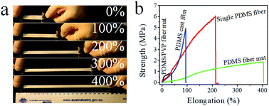
Fig. 3a shows the stress–strain curves of PDMS fibers. It was interesting to note that individual PDMS fibers had an elongation at break as high as 212%. This was significantly larger than that of PDMS film prepared by a casting method, which was only 93%. Moreover, the single PDMS fiber showed higher tensile strength (6.0 MPa) than the PDMS cast film (4.9 MPa). The PDMS fiber mats showed much larger elongation at break (over 400%) than the single PDMS fibers. This result is completely different to interconnected PDMS fibers reported by other researchers.20 Interconnected PDMS fiber mats only exhibited a small elongation ratio because the inter-fiber interconnections restrained the deformation of PDMS fibers, making the fibrous mat have a similar elongation ratio to PDMS casting film. In addition, the tensile strength of PDMS fiber mats (1.8 MPa) was lower. The small tensile strength of PDMS fiber mats is due to the highly porous structure of the fiber mats and the use of the overall cross-sectional dimension (mat width × thickness) for the calculation of tensile strength.


image file: c4ra00232f-f3.tif
Fig. 3 (a) Strength–elongation curves of single PDMS fiber, PDMS/PVP fiber mat, PDMS fiber mat, and PDMS cast film, (b) photos of a PDMS fiber mat drawn at different elongation ratios, (c) & (d) cyclic tensile test of (c) PDMS fiber mat and (d) PDMS fiber mat containing ethanol.

For comparison, the stress–strain curve of PDMS/PVP core–sheath fiber mats is also shown in Fig. 3a. The PDMS/PVP fiber mats had a small elongation at break, only 37%. The tensile strength of PDMS/PVP fiber mats (0.8 MPa) was lower than that of PDMS fiber mats.

To demonstrate the unusually large elongation at break, the photos of a PDMS fiber mat being drawn to different lengths are shown in Fig. 3b. Upon elongation, the PDMS fiber mat width was narrowed down evenly. When the strip was drawn 4 times its original length, the strip width reduced from 10.0 mm to 6.4 mm.

Fig. 3c shows the cyclic loading tests of PDMS fiber mats. By stretching and retracting the fibrous strip at a constant rate of 10 mm min−1, the variation of stress was recorded. A Mullins effect with a typical hysteresis loop was observed. Such hysteresis loops were derived from the slippage of PDMS fibers within the fibrous matrix. The loading stress was always higher than that of unloading one because of the energy dissipation. A similar Mullins effect was also reported on electrospun polyurethane nanofibers.26

The fibrous strip showed different recovery behavior after elongation, depending on the elongation ratio. When the elongation was less than 2 times the original length (i.e. drawing ratio <2), the stretched strip can return to the original length. However, larger drawing ratios led to unrecoverable deformation, and the unrecoverable length increased with the increasing drawing ratio from 2 to 4. This was attributed to the compact fibrous structure and friction forces formed among the fibers during recovery from the stretched state. Steric hindrance and inter-fiber friction prevented fibers from moving back to the original structure. To confirm the large friction effect, liquid ethanol was dropped onto the fiber mat and the cycling tests were repeated. Ethanol functioned to lubricate the fibers, reducing inter-fiber friction. As expected, an evident reduction in both loading and unloading forces was observed during stretching and retracting processes (Fig. 3d).

To find the source of the remarkable elongation at break, PDMS fibers and cast film were subjected to an X-ray diffraction (XRD) test. As shown in Fig. 4a, PDMS in PDMS/PVP fibers had stronger and shaper diffraction peak at 12.1°, suggesting higher crystalline content of PDMS. The broad peak at 21.8° indicated that PDMS was largely in the amorphous state.27 In comparison, PDMS fibers and PDMS casting film had lower diffraction peak at 12.1°. PDMS in the core–sheath fibers had higher crystalline structure than PDMS fibers and PDMS cast film.


image file: c4ra00232f-f4.tif
Fig. 4 SEM images of PDMS fibers at different elongation ratios (inset images are the FFT frequency images), and XRD patterns of PDMS/PVP core–sheath fibers, PDMS fibers, and PDMS casting film.

When the PVP sheath layer was dissolved, PDMS core shrank largely. This can be explained as that crosslinked polymer molecules relaxed their structure, as illustrated in Fig. 5a. During stretching, PDMS fiber was firstly reduced its size to that was in core–sheath fibers, and then stretched down to a smaller diameter. The post-crosslinking and structural relaxation after removal of fiber sheath allowed the PDMS fibers to have much larger elongation at break than the cast films.


image file: c4ra00232f-f5.tif
Fig. 5 Schematic illustration of (a) individual PDMS/PVP fiber before and after dissolving PVP sheath, and (b) PDMS fiber mat being at different elongation ratios.

SEM imaging was used to examine the deformation of PDMS fiber mast at different elongation ratios. As shown in Fig. 4b, PDMS fibers tended to align along the drawing direction during stretching. The average fiber diameter remained almost unchanged with the drawing until the fiber mat was drawn to an elongation ratio of 200%, and the fibrous morphology showed little change with stretching at this stage. Further increasing the elongation ratio from 200% to 400% led to a linear decrease in the average fiber diameter (see ESI, Fig. S2). When the elongation ratio was above 300%, PDMS fibers showed a highly aligned structure along the drawing direction.

The fiber alignment degree was calculated based on the SEM images. As shown in the inset of Fig. 4, white pixels concentrated in a symmetric, circular pattern around the origin in the FFT image of PDMS fibers without stretching. With increasing the drawing ratio, white pixels distribution changed into an elliptic pattern, attributable to the fiber alignment along the stretching direction. Based on these results, the elongation of PDMS fiber mats can be divided into two steps:

(1) At a low elongation ratio, PDMS fibers align along the stretching direction. At this stage, PDMS molecular orientation has little change with elongation.

(2) At a high elongation ratio, PDMS fibers are highly aligned and PDMS molecular chains also orientate along the fiber axis direction.

The remarkable elongation performance of PDMS fiber mats and associated molecular chain alignment are illustrated in Fig. 5b.

Conclusions

Continuous PDMS fibers have been prepared successfully by core–shell electrospinning of a liquid PDMS precursor and a thermoplastic sheath, in situ curing treatment of the PDMS core, and finally dissolving off the sheath layer. PDMS fiber mats and single PDMS fibers showed an elongation ratio at break as high as 403% and 212%, respectively, both of which are significantly larger than those of the dense film counterparts. Single PDMS fibers also show higher tensile strength than PDMS cast film. PDMS fiber mats exhibit Mullins effect with a typical hysteresis loop in the cyclic loading test. The superior elastic feature has been attributed to PDMS molecular orientation within the fibers and randomly-orientated fibrous structure. This highly-elastic PDMS fibers may find applications for artificial skin, wounding healing, filtration, sensors, catalysis, and functional textiles.

Acknowledgements

The authors thank Nanomechanics Research Lab for assisting in testing the tensile property of single PDMS fibers.

Notes and references

  1. L. Li, Z. Xiao, S. Tan, L. Pu and Z. Zhang, J. Membr. Sci., 2004, 243, 177–187 CrossRef CAS PubMed .
  2. C. P. B. Siu and C. Mu, J. Microelectromech. Syst., 2008, 17, 1329–1341 CrossRef CAS .
  3. T. Yamada, Y. Hayamizu, Y. Yamamoto, Y. Yomogida, A. Izadi-Najafabadi, D. N. Futaba and K. Hata, Nat. Nanotechnol., 2011, 6, 296–301 CrossRef CAS PubMed .
  4. E. Eteshola and D. Leckband, Sens. Actuators, B, 2001, 72, 129–133 CrossRef CAS .
  5. T. Fujii, Microelectron. Eng., 2002, 61–62, 907–914 CrossRef CAS .
  6. E. Leclerc, Y. Sakai and T. Fujii, Biomed. Microdevices, 2003, 5, 109–114 CrossRef CAS .
  7. D. Y. Lee, D. H. Lee, H. S. Lim, J. T. Han and K. Cho, Langmuir, 2009, 26, 3252–3256 CrossRef PubMed .
  8. J. Tamelier, S. Chary and K. L. Turner, Langmuir, 2012, 28, 8746–8752 CrossRef CAS PubMed .
  9. C. Xu, R. Inai, M. Kotaki and S. Ramakrishna, Tissue Eng., 2004, 10, 1160–1168 CrossRef CAS PubMed .
  10. E. R. Kenawy, G. L. Bowlin, K. Mansfield, J. Layman, D. G. Simpson, E. H. Sanders and G. E. Wnek, J. Controlled Release, 2002, 81, 57–64 CrossRef CAS .
  11. K. Kim, Y. K. Luu, C. Chang, D. Fang, B. S. Hsiao, B. Chu and M. Hadjiargyrou, J. Controlled Release, 2004, 98, 47–56 CrossRef CAS PubMed .
  12. E. Luong-Van, L. Grrndahl, K. N. Chua, K. W. Leong, V. Nurcombe and S. M. Cool, Biomaterials, 2006, 27, 2042–2050 CrossRef CAS PubMed .
  13. K. Yoon, K. Kim, X. Wang, D. Fang, B. S. Hsiao and B. Chu, Polymer, 2006, 47, 2434–2441 CrossRef CAS PubMed .
  14. R. Gopal, S. Kaur, Z. Ma, C. Chan, S. Ramakrishna and T. Matsuura, J. Membr. Sci., 2006, 281, 581–586 CrossRef CAS PubMed .
  15. X. Wang, C. Drew, S.-H. Lee, K. J. Senecal, J. Kumar and L. A. Samuelson, Nano Lett., 2002, 2, 1273–1275 CrossRef CAS .
  16. X. Wang, Y.-G. Kim, C. Drew, B.-C. Ku, J. Kumar and L. A. Samuelson, Nano Lett., 2004, 4, 331–334 CrossRef CAS .
  17. M. M. Demir, M. A. Gulgun, Y. Z. Menceloglu, B. Erman, S. S. Abramchuk, E. E. Makhaeva, A. R. Khokhlov, V. G. Matveeva and M. G. Sulman, Macromolecules, 2004, 37, 1787–1792 CrossRef CAS .
  18. S. W. Choi, S. M. Jo, W. S. Lee and Y.-r. Kim, Adv. Mater., 2003, 15, 2027–2032 CrossRef CAS .
  19. M. Mohamed, International Pat., WO 2008/088730 A2, 2008 .
  20. Y. B. Kim, D. Cho and W. H. Park, J. Appl. Polym. Sci., 2009, 114, 3870–3874 CrossRef CAS .
  21. D. Yang, X. Liu, Y. Jin, Y. Zhu, D. Zeng, X. Jiang and H. Ma, Biomacromolecules, 2009, 10, 3335–3340 CrossRef CAS PubMed .
  22. S. Lu, X. Duan, Y. Han and H. Huang, J. Appl. Polym. Sci., 2013, 128, 2273–2276 CrossRef CAS .
  23. C. Bai, X. Zhang and J. Dai, Prog. Org. Coat., 2007, 60, 63–68 CrossRef CAS PubMed .
  24. B.-Y. Kim, L.-Y. Hong, Y.-M. Chung, D.-P. Kim and C.-S. Lee, Adv. Funct. Mater., 2009, 19, 3796–3803 CrossRef CAS .
  25. H. Niu, J. Zhang, Z. Xie, X. Wang and T. Lin, Carbon, 2011, 49, 2380–2388 CrossRef CAS PubMed .
  26. K. Lee, B. Lee, C. Kim, H. Kim, K. Kim and C. Nah, Macromol. Res., 2005, 13, 441–445 CrossRef CAS .
  27. G. L. Jadav, V. K. Aswal and P. S. Singh, J. Mater. Chem. A, 2013, 1, 4893–4903 CAS .

Footnote

Electronic supplementary information (ESI) available: There are two supplementary files, TGA curves of PDMS/PVP and PDMS fibers and influence of elongation ratio on PDMS fiber diameter. See DOI: 10.1039/c4ra00232f

This journal is © The Royal Society of Chemistry 2014
Click here to see how this site uses Cookies. View our privacy policy here.