Rapid-flux-solvent-atmosphere method for tailoring the morphology of titania substrates over a large area via direct self-assembly of block copolymers

Gianpaolo Chieffia, Rocco Di Girolamob, Antonio Aronnea, Pasquale Pernicea, Esther Fanellia, Massimo Lazzaric, Claudio De Rosab and Finizia Auriemma*b
aDipartimento di Ingegneria Chimica, dei Materiali e della Produzione Industriale, Università di Napoli Federico II, Piazzale Tecchio 80, 80125 Naples, Italy
bDipartimento di Scienze Chimiche, Università di Napoli Federico II, Complesso Monte Sant'Angelo, via Cintia, 80126, Napoli, Italy. E-mail: finizia.auriemma@unina.it; Fax: +39 081 674090; Tel: +39 081 674341
cCentre for Research in Biological Chemistry and Molecular Materials (CIQUS), University of Santiago de Compostela, 15782, Santiago de Compostela, Spain

Received 6th January 2014 , Accepted 17th February 2014

First published on 18th February 2014


Abstract

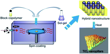
A fast method to direct the self-assembly of block copolymers loaded with metal oxide precursors in specific domains is demonstrated. It consists of performing spin-coating in a controlled atmosphere under a flux of solvent vapors (rapid-flux-vapor-atmosphere). Nanostructured thin films of hybrid composites and regular titania substrates, well oriented over a large area, are rapidly obtained.


In the past decades, there has been tremendous progress in the development of methods for surface decoration with nano-motifs of inorganic materials possessing a regular shape and uniform size, organized on the nanometer scale over a large area.1,2 The interest toward these systems derives from the intrinsic properties of nano-sized inorganic particles at a fundamental level arising from both isolated entities, and their ensembles.2,3 In particular, titanium dioxide nanoparticles have received considerable attention because of their electronic and photocatalytic properties, coupled with their low cost and safety toward the environment and human health.4 These properties make TiO2 nanoparticles suitable for a wide range of applications, such as in the fields of solar cells (DSSCs),5a–c electric and photocatalytic systems,5d,e and gas sensing.5f

In order to best exploit the intrinsic and ensemble properties of TiO2 nanocrystal assemblies on the nanometer scale, a large number of methods for the preparation of nanostructured titania substrates, with well controlled morphology, have been developed. One of the most successful approaches relies on the combination of the sol–gel technique and the self-assembly of an amphiphilic block copolymer (BCP) acting as template.4,6,7,8 Arrays of titania nanoparticles, of well defined morphology, covering the whole area of the substrate may be created by drop casting or spin coating solutions of titanium species and a BCP in a non-selective solvent. This exploits the preferential interactions between the titanium compound and the hydrophilic domains of the BCP.7,8 The final morphology is dictated by the tendency of the covalently linked, chemically distinct, macromolecules constituting amphiphilic BCPs, to segregate into different domains in order to minimize their mutual repulsions. This results in the spontaneous formation of different types of nanostructures (spheres, cylinders and lamellae).9 In the presence of a titanium compound, hybrid nanostructures are formed, in which the BCP matrix acts as a host for sequestering the guest Ti-species10 in the hydrophilic domains during the sol–gel process.7,8 Upon removal of the organic matrix, dot-, or worm-like entities, cylinders, nanoclusters, and nanoporous networks of titania are obtained, reminiscent of the domain-organized nanostructure achieved in the hybrid system. The final morphology of the titania substrates, on the nanometer scale, may be finely controlled by selecting the preparation method of the hybrid composite and the successive processes adopted for the removal of the organic component.7,8

The problem of how to produce titania nanostructured substrates, with a well defined morphology, has been extensively tackled. The intricate kinetics and thermodynamic phenomena underlying the whole process have been partially understood at a fundamental level. Although several methods for the preparation of titania substrates with a controlled morphology have already been reported,5,8 the issue related to the control of the structural organization of the inorganic nanoparticles, on the nanometer scale over a large area, using a fast process at a low cost, is still a challenge.

In this communication, a quick, simple and low cost method for preparing hybrid nanostructures and highly uniform titania substrates having a tailored morphology over a large area, with high reproducibility, is rationally devised. The method is based on the combined use of the self-assembly of a block copolymer and the sol–gel process of a titania precursor. In this way, very rapidly, hybrid nanostructured thin films can be obtained through the direct self-assembly of the BCP via spin coating of the BCP/Ti-species solutions under a flux of solvent vapors to attain a controlled atmosphere. The method, here named rapid-flux-solvent-atmosphere (RFSA), is of particular interest for systems that require a short processing time to eliminate the solvent, so that a tight control over the final morphology of the hybrid system over a large area can be obtained. This method also prevents the hydrolysis and condensation reactions of the titanium species that would overwhelm the self assembly of the organic matrix.

The RFSA method is demonstrated in the case of an amphiphilic polystyrene-block-poly(ethylene oxide) (PS-PEO) diblock copolymer. This copolymer has a number average molecular mass Mn of 136[thin space (1/6-em)]000 g mol−1, and a volume fraction of PEO blocks of ≈0.20. The method is able to form a microphase-separated morphology, in which PEO cylinders are hexagonally arranged in the PS matrix. The PS-PEO BCP was selected in order to use the PEO domains as hosts for the selective inclusion of titanium species to obtain nanostructured hybrid systems via the sol–gel technique. Sample solutions (preparation time ≈ 90 min) with relative Ti contents of 10 and 40 mol% (mol Ti[thin space (1/6-em)]:[thin space (1/6-em)]mol PEO monomeric units) were obtained by mixing a 1 wt% PS-PEO toluene solution with a toluene[thin space (1/6-em)]:[thin space (1/6-em)]isopropanol solution (1[thin space (1/6-em)]:[thin space (1/6-em)]1 volume ratio) having the same concentration of titanium tetraisopropoxide (TTIP) (0.0125 M) and water. All of the solutions were used immediately after preparation to obtain thin films on a silicon substrate by spin coating using different protocols.

Typical field-emission scanning electron microscopy (FESEM) images of the thin films of the neat BCP and hybrid systems are shown in Fig. 1. In the case of the neat BCP (Fig. 1A), a pseudo-hexagonal array of PEO cylinders, vertically oriented to the film surface, appear as dark spots embedded in the bright PS matrix with low lateral order. The vertical orientation of the PEO cylindrical domains is controlled by the film thickness (≈70 nm), which is maintained at similar values to the average distance between the centers of neighboring domains, dc–c ≈ 69 nm. The average diameter of the cylinders is D ≈ 40 nm, even though cylinders possessing diameters of almost double that value are also present, formed due to the coalescence of neighboring cylinders into single domains.


image file: c4ra00110a-f1.tif
Fig. 1 FESEM images of the thin films of neat PS-PEO BCP (A and D), hybrid BCP–TiOx composites containing 10 (B) and 40 mol% Ti (C, E and F), and corresponding heat treated (600 °C at a rate of 2 °C min−1 for 4 h) titania substrates (B′, C′, E′ and F′). Spin coating was performed in ambient atmosphere for A–C and in water–toluene (1[thin space (1/6-em)]:[thin space (1/6-em)]1 volume ratio) vapor atmosphere for D–F after 30 min (D, F, 62% RH) and 3 min (E, 36% RH) contact time. The FFTs of FESEM images A–C and D–F are shown in the insets.

The cylindrical morphology is also maintained in the BCP–TiOx hybrid systems (Fig. 1B and C). The selective inclusion of titanium species into the PEO domains is indicated by the fact that the PEO domains remain dark. At 10 mol% Ti concentration the cylindrical domains are vertically oriented (Fig. 1B) as in the neat BCP, whereas at 40 mol% Ti, PEO domains with an irregular worm-like shape are also formed beside those with vertical orientations (Fig. 1C).

The average values of the diameter, D and the center-to-center distance, dc–c of the PEO domains decrease with the increase in the Ti concentration (D ≈ 30 nm, dc–c ≈ 65 nm at 10 mol% Ti; D = 20 nm and dc–c = 60 nm at 40 mol% Ti). The decrease in the D and dc–c parameters with the increase in the concentration of Ti species in the hybrid systems, is in agreement with the results presented in ref. 7a. Accordingly, based on ref. 11, this decrease has been attributed to the effect generated by improvement in the solvent quality toward the hydrophilic PEO chains on the complex micellization behavior of the amphiphilic BCPs. In fact, as the titanium concentration increases, the relative amount of isopropanol also increases, resulting in a better solvent for the PEO chains. As a consequence, the interfacial tension and the number of BCP chains participating in each cylindrical aggregate, decrease and domains of a smaller size are formed. However, an additional factor that may influence the size of the PEO domains may be the formation of PEO/TiOx molecular complexes with diverse molar ratios which affect the development of different crystalline forms. This has already been reported in the case of other PEO complexes strongly stabilized by hydrogen bonding.12 These different crystalline organizations, are likely to induce dimensional changes in the self-assembly of the cylindrical meso-domains.

In all cases, the fast Fourier transform (FFT) of the FESEM images shows a ring-shaped pattern (inset of Fig. 1A–C). The correlation distance of the PEO domains evaluated from the FFT images (Fig. 2A) is close to the center-to-center distance of the neighboring PEO domains, dc–c, evaluated by direct analysis of the FESEM micrographs (see section S6).


image file: c4ra00110a-f2.tif
Fig. 2 (A) Radially averaged spectral intensity distribution extracted from the fast Fourier transforms of the FESEM images in the insets of Fig. 1A, C–F and 3B and B′. The second and third order correlation peaks are indicated with an asterisk. (B) Three-dimensional AFM height image of the annealed sample obtained from the BCP solution with 40 mol% Ti, corresponding to the FESEM image of Fig. 1C.

The uniform distribution of Ti species inside the PEO domains is clearly demonstrated by the FESEM images (Fig. 1B′ and C′) relative to the hybrid thin films heat-treated at 600 °C. At 460 °C the organic matrix is almost completely degraded (Fig. S1), even if the presence of the Ti species slightly increases the thermal stability of the BCP.8d Furthermore, at 600 °C, amorphous titania is completely transformed into anatase (curve c of Fig. S2). Therefore, the 600 °C treated substrates (Fig. 1B′ and C′) essentially consist of anatase nanoclusters uniformly spread all over the surface, whose morphology is reminiscent of the morphology seen in the initial hybrid film (Fig. 1B and C). No significant coalescence phenomena are observed during prolonged annealing at 600 °C. This is probably because the domain spacing of the templating BCP matrix in the hybrid systems is large enough to prevent the merging of neighbouring titania nanoclusters into larger clusters. The average size of the titania nanoclusters decreases from a value of ≈30–35 nm for 10 mol% Ti (Fig. 1B′) to ≈20–25 nm for 40 mol% Ti (Fig. 1C′). The average distance between neighboring titania nanoclusters of ≈60–65 nm, is close to the dc–c value of neighboring PEO domains in the corresponding hybrid systems (Fig. 1B and C). Simultaneously, the degree of coverage of the silicon substrates with titania nanoclusters increases from 18 to 50% (section S4). The three-dimensional atomic force microscopy (AFM) height images of the heat treated samples obtained from the BCP solution with 40 mol% Ti (Fig. 2B) show a landscape of TiO2 nano-pillars, 4–10 nm in height, standing up from the substrate surface with low lateral order.

In order to achieve better orientational control of the titania loaded PEO domains, we have used a quite fast and direct self-assembly approach, similar to that proposed in ref. 13 in the case of neat BCP. The process consists of performing spin coating under a controlled vapor atmosphere in a closed tank, where the atmosphere is regulated by placing a solvent in a Petri dish. Spin coating is initiated only after partial saturation of the environment with the solvent vapor. A water–toluene mixture in a 1[thin space (1/6-em)]:[thin space (1/6-em)]1 volume ratio (mol ratio ≈ 4[thin space (1/6-em)]:[thin space (1/6-em)]1) is used and spin coating is applied after a 30 min delay. Since the vapor pressure of toluene and water at room temperature are nearly identical (≈26 torr),14 the use of mixed solvents corresponds, according to Raoult's law, to a water vapor pressure of about four times higher than toluene, resulting in an atmosphere richer in water vapor. The results are illustrated in Fig. 1D–F.

The FESEM image for the thin film of the neat BCP prepared under a water–toluene vapor atmosphere (Fig. 1D, relative humidity, RH ≈ 60%) shows a more uniform and regular morphology than that obtained under an ambient atmosphere (Fig. 1A). Vertically oriented PEO cylinders with improved lateral order and uniform diameter develop in these conditions. The result shown in Fig. 1D may be understood by considering the fact that toluene, at room temperature (≈22 °C), is a good solvent for PS and is less good for PEO blocks, whereas water is a good solvent only for PEO (section S3). Therefore, by using a vapor solvent environment during the spin coating process, it is possible to modify the atmosphere in the chamber from a toluene vapor rich to a water vapor rich atmosphere. Changes in the morphology occur because the interfacial energy at the air/film interface changes from being PS favorable, to an atmosphere that is also favorable for PEO.13

Using the Voronoi construction to count the number of first neighboring domains to each PEO domain (section S5), a figure of merit is associated to the FESEM images of Fig. 1A and D. This addresses the degree of hexagonal order, given by the ratio between the number of hexa-coordinated PEO domains, Nhexa, to the total number of domains, Ntot, Rhexa = 100 Nhexa/Ntot. Accordingly, for the thin films of neat BCP, the degree of hexagonal order, Rhexa, increases from 35% in the case of spin coating under an ambient atmosphere, to 53% in the case of spin coating under a water–toluene (RH ≈ 60%) vapor atmosphere, and a 30 min contact time.

However, when the same protocol is applied to spin coating of BCP solutions containing titanium species, a worm-like disordered morphology is obtained for the hybrid composites. This is scarcely reminiscent of the cylindrical morphology of the neat BCP thin films prepared under the same conditions. This is illustrated in the FESEM images of (Fig. 1E and F) relative to the thin films of the hybrid composites, prepared by spin coating BCP solutions of 40 mol% Ti under water–toluene vapors using 3 min (≈36% RH) and 30 min (≈60% RH) contact time. The corresponding annealed samples (Fig. 1E′ and F′) show titania nanoclusters uniformly dispersed on the substrate, with an area coverage of ≈24 and 40%, respectively. Compared to the nanoclusters that remain small and well separated entities in the case of Fig. 1E′, the nanoclusters form a continuous dendritic network in Fig. 1F′. These data indicate that during the aging time of the solution on the silicon substrates prior to the spin coating process and consequent evaporation of the solvent, the sol–gel reactions of the hydrolysis and condensation of TTIP occur, in such a way that the self-assembly process of the BCP becomes completely dominated.8

In the final steps of the present investigation, the spin coating chamber was modified in order to achieve the desired relative humidity value in less than one minute, in such a way that the confinement of titanium species inside the PEO domains is “frozen” and the cylindrical morphology of the BCP is preserved. This aim is realized under a flux of a vapor solvent using compressed air as the carrier (Fig. 3A).


image file: c4ra00110a-f3.tif
Fig. 3 (A) Closed tank for spin coating under a flux of solvent vapors equipped with a digital hygrometer automatically recording the values of the relative humidity and temperature every 2 s. (B, B′ and B′′) FESEM images of the thin films of neat PS-PEO BCP (B), hybrid composite with 40 mol% Ti (B′) and corresponding annealed (600 °C at a rate of 2 °C min−1 for 4 h) titania substrate (B′′). In the RFSA protocol, spin coating was applied for 30 s under a flux of water–toluene vapors at 1[thin space (1/6-em)]:[thin space (1/6-em)]1 vol ratio after 20 s contact time at ≈52% RH in B, and ≈45% RH in B′. The FFTs of the FESEM images in B and B′ are shown in the insets.

This “rapid-flux-solvent-atmosphere” (RFSA) method allows the easy tailoring of the solvent vapor atmosphere in the desired amount of time, by simply varying the flux and/or the solvent temperature while recording the values of the temperature and RH in the tank every 2 s. Spin coating is initiated only after a pre-fixed contact time (RFSA time) of the solution with the solvent vapor atmosphere of 20 s in Fig. 3. The RH value recorded after 25 s, that is the RH value reached in the tank 5 s after beginning of the spin coating process, is specified.

The FESEM image of the neat BCP thin films, subjected to 20 s RFSA time under a water–toluene (≈50% RH) vapor atmosphere is shown in Fig. 3B. Highly regular and uniform nanostructures on the whole substrate are obtained, consisting of PEO cylinders with perpendicular orientations, a diameter of D ≈ 40 ± 5 nm, embedded in the PS matrix at a distance of dc–c ≈71 ± 3 nm. The degree of hexagonal order of these resultant nanostructures, Rhexa, equal to 70%, is higher than the one achieved with 30 min contact time in the same vapor atmosphere (60% RH, Fig. 1D, Rhexa, = 50%). Furthermore, the radially averaged spectral intensity distribution extracted from the FFT of the corresponding FESEM image (inset of Fig. 3B) shows a second and third order correlation peak (curve c of Fig. 2A). This indicates that the beneficial effect of the high level of water vapor may be enhanced by using a short RFSA time (20 s).

The effect of the 20 s RFSA time (≈45% RH) protocol under a water–toluene atmosphere is also beneficial in the case of the 40 mol% Ti BCP solution as shown by the FESEM image of Fig. 3B′. The RH value is lower than Fig. 3B because the flow rate of the compressed air was slightly reduced. A cylindrical morphology of the PEO domains in the PS matrix similar to that of the neat BCP thin films prepared under similar RFSA conditions (Fig. 3B) is obtained. This presents PEO cylinders with an average diameter of D ≈ 35 ± 5 nm at distance of dc–c ≈ 70 ± 10 nm. A remarkable increase in the degree of hexagonal order, Rhexa, is reached, from a value of 30% in the case of the hybrid nanostructure prepared under an ambient atmosphere (Fig. 1D) to 60%.

The FESEM image of the corresponding annealed sample is shown in Fig. 3B′′. The annealing of the RFSA substrate of Fig. 3B′ produces a spot-like array of isolated titania nanoclusters, uniformly covering the macroscopic substrate, with a diameter of D ≈ 30 ± 8 nm, a center-to-center distance of dc–c ≈ 80 ± 10 nm and an average height of 10 ± 2 nm (Fig. S5), reminiscent of the morphology shown by the initial hybrid system (Fig. 3B′). It is worth noting that in the case of the BCP solution with 40 mol% Ti hybrid films prepared by spin coating under an ambient atmosphere, annealing produces nanostructures where the shapes of titania nanoclusters are irregular and include both dot-like and worm-like entities (Fig. 1C′). This makes any evaluation of the degree of hexagonal order difficult, and only the degree of coverage equal to ≈50% can be estimated. However, in the case of the titania substrates obtained by heat treatment of the RFSA system, a coverage of ≈26% is obtained with the advantage that the shape of titania nanoclusters is more regular (Fig. 3B′′). This allows the calculation of a degree of hexagonal order which is ≈40%.

Conclusions

A fast, easy and simple method, addressing the intrinsic difficulty in dealing with the sol–gel process coupled with the self-assembly of block copolymers is identified. This method allows hybrid composites to be prepared in a single step and with high reproducibility. The composites consist of a BCP with selective inclusion of a titania precursor in specific domains. These systems are prepared by spin coating freshly prepared solutions of BCP/titanium species in a closed tank under a controlled atmosphere of solvent vapors which are able to establish good interactions with the BCP blocks. We demonstrate that a tight control over the orientation and degree of lateral order of the BCP domains may be achieved in the hybrid systems over a large area using this protocol, provided that the contact time of the solution with the vapors before application of the spin coating is very short. In order to use short contact times, a flux of solvent vapors are directed inside the closed tank in the RFSA protocol, so that the desired atmosphere is rapidly reached. Robust titania substrates with a morphology reminiscent of the one achieved in the corresponding hybrid composites are thus obtained, by successive heat treatments. More generally, the RFSA protocol coupled with the selective confinement of a metal oxide species in the hydrophilic blocks of an amphiphilic BCP and successive heating at high temperatures, provides a fast, simple and prompt assembly tool to obtain substrates uniformly covered with metal oxide nanoparticles over a large area. This method is potentially suitable for optoelectronic, sensing and catalysis applications, where long range order (periodicity) is key for achieving high performance.

Acknowledgements

The authors thank the “Ministero dell'Istruzione, dell'Università e della Ricerca” (PRIN2010-2011 and FIRB 2012 Futuro in Ricerca, RBFR122HFZ) from Italy and the Xunta de Galicia (PX2010/168-2) from Spain for financial support.

Notes and references

  1. (a) C. B. Murray, C. R. Kagan and M. G. Bawendi, Annu. Rev. Mater. Sci., 2000, 30, 545 CrossRef CAS; (b) Z. Quan and H. Y. Fang, Nano Today, 2010, 5, 390 CrossRef CAS PubMed; (c) M. C. Orilall and U. Wiesner, Chem. Soc. Rev., 2011, 40, 520 RSC.
  2. (a) W. A. Lopes and H. M. Jager, Nature, 2001, 414, 735 CrossRef CAS PubMed; (b) T. P. Bigioni, X.-M. Lin, T. T. Nguyen, E. Corwin, T. A. Witten and H. M. Jaeger, Nat. Mater., 2006, 5, 265 CrossRef CAS PubMed.
  3. (a) J. Cheon, N.-J. Kang, S. M. Lee, J.-H. Yoon and S. Oh, J. Am. Chem. Soc., 2004, 126, 1950 CrossRef CAS PubMed; (b) E. Roduner, Chem. Soc. Rev., 2006, 35, 583 RSC.
  4. W. Li, Z. Wu, J. Wang, A. A. Elzatahry and D. Zhao, Chem. Mater., 2013, 26, 287 CrossRef.
  5. (a) U. Bach, D. Lupo, P. Comte, J. E. Mose, F. Weissörtel, J. Salbeck, H. Spreitzer and M. Grätzel, Nature, 1998, 395, 583 CrossRef CAS PubMed; (b) Y. Lee and M. Kang, Mater. Chem. Phys., 2010, 122, 284 CrossRef CAS PubMed; (c) Z. Liu, Y. Li, Z. Zhao, Y. Cui, K. Hara and M. Miyauchi, J. Mater. Chem., 2010, 20, 492 RSC; (d) A. R. Khataee and M. B. Kasiri, J. Mol. Catal. A: Chem., 2010, 328, 8 CrossRef CAS PubMed; (e) Q. Zhang, J.-B. Joo, Z. Lu, M. Dahl, D. Q. L. Oliveira, M. Ye and Y. Yin, Nano Res., 2011, 4, 103 CrossRef CAS PubMed; (f) Y. Wang, G. Du, H. Liu, D. Liu, S. Qin, N. Wang, C. Hu, X. Tao, J. Jiao, J. Wang and Z. L. Wang, Adv. Funct. Mater., 2008, 18, 1131 CrossRef CAS PubMed.
  6. (a) B. Smarsly and M. Antonietti, Eur. J. Inorg. Chem., 2006, 1111 CrossRef CAS PubMed; (b) D. Grosso, G. J. d A. A. Soler-Illia, E. L. Crepaldi, F. Cagnol, C. Sinturel, A. Bourgeois, A. Brunet-Bruneau, H. Amenitsch, P. A. Albouy and C. Sanchez, Chem. Mater., 2003, 15, 4562 CrossRef CAS; (c) P. Yang, D. Zhao, D. I. Margolese, B. F. Chmelka and G. D. Stucky, Nature, 1998, 396, 152 CrossRef CAS PubMed; (d) G. J. A. A. Soler-Illia, P. C. Angelomé, M. C. Fuertes, D. Grosso and C. Boissiere, Nanoscale, 2012, 4, 2549 RSC.
  7. (a) D. H. Kim, Z. Sun, T. P. Russell, W. Knoll and J. S. Gutmann, Adv. Funct. Mater., 2005, 15, 1160–1164 CrossRef CAS PubMed; (b) D. Scalarone, J. Tata, F. Caldera, M. Lazzari and O. Chiantore, Mater. Chem. Phys., 2011, 128, 166 CrossRef CAS PubMed; (c) X. Li, K. H. A. Lau, D. H. Kim and W. Knoll, Langmuir, 2005, 21, 5212 CrossRef CAS PubMed.
  8. (a) Y.-J. Cheng and J. S. Gutmann, J. Am. Chem. Soc., 2006, 128, 4658 CrossRef CAS PubMed; (b) Y.-J. Cheng, S. Zhou, M. Volkenhauer, G.-G. Bumbu, S. Lenz, M. Memesa, S. Nett, S. Emmerling, W. Steffen and J. S. Gutmann, Eur. J. Inorg. Chem., 2013, 1127 CrossRef CAS PubMed; (c) Y. J. Cheng, P. Muller-Buschbaum and J. S. Gutmann, Small, 2007, 3, 1379–1382 CrossRef CAS PubMed; (d) J. Gutierrez, A. Tercjak, I. Garcia, L. Peponi and I. Mondragon, Nanotechnology, 2008, 19, 15560 CrossRef PubMed.
  9. G. H. Fredrickson and F. S. Bates, Annu. Rev. Phys. Chem., 1990, 41, 525 CrossRef PubMed.
  10. M. R. Bockstaller, R. A. Mickiewicz and E. L. Thomas, Adv. Mater., 2005, 17, 1331 CrossRef CAS PubMed.
  11. U. Jeong, D. Y. Ryu, D. H. Kho, D. H. Lee, J. K. Kim and T. P. Russell, Macromolecules, 2003, 36, 3626 CrossRef CAS; Y. Seo, M. W. Kim, D. H. Ou-Yang and D. G. Peiffer, Polymer, 2002, 43, 5629 CrossRef.
  12. (a) P. Iannelli, P. Damman, M. Dosiere and J.-F. Moulin, Macromolecules, 1999, 32, 2293 CrossRef CAS; (b) J. Tata, D. Scalarone, M. Lazzari and O. Chiantore, Eur. Polym. J., 2009, 45, 2520 CrossRef CAS PubMed.
  13. S. Kim, R. M. Briber, A. Karim, R. L. Jones and H.-C. Kim, Macromolecules, 2007, 40, 4102 CrossRef CAS.
  14. E. B. Munday, J. C. Mullins and D. D. Edie, J. Chem. Eng. Data, 1980, 25, 191–194 CrossRef CAS.

Footnote

Electronic supplementary information (ESI) available: S1. Materials and methods; S2. Heat treated systems; S3. Quality of solvents; S4. Calculation of the degree of coverage of the titania nanoclusters on the silicon surface; S5. Voronoi constructions; S6. Radial profile analysis of FFT-FESEM images. S7. Distribution of the height of TiO2 nanopillars. See DOI: 10.1039/c4ra00110a

This journal is © The Royal Society of Chemistry 2014
Click here to see how this site uses Cookies. View our privacy policy here.