New layer-by-layer Nb2O5–TiO2 film as an effective underlayer in dye-sensitised solar cells

L. F. Paulaa, R. C. Amaralb, N. Y. Murakami Ihab, R. M. Paniagoc, A. E. H. Machadoa and A. O. T. Patrocinio*a
aInstituto de Química, Universidade Federal de Uberlândia, 38400-902 Uberlândia, MG, Brazil. E-mail: otaviopatrocinio@iqufu.ufu.br
bLaboratory of Photochemistry and Energy Conversion, LFCE, Instituto de Química, Universidade de São Paulo, 05508-900, São Paulo, SP, Brazil
cDepartamento de Física, Universidade Federal de Minas Gerais 31270-010 Belo Horizonte, MG, Brazil

Received 3rd January 2014 , Accepted 31st January 2014

First published on 31st January 2014


Abstract

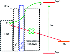
Highly efficient all-inorganic TiO2–Nb2O5 underlayers for dye-sensitised solar cell applications were produced by the layer-by-layer technique (LbL). TiO2 and Nb2O5 nanoparticles were prepared by the sol–gel method under acidic and alkaline conditions, respectively. The LbL films exhibited a very compact and homogeneous surface, as shown in FESEM and AFM images, which ensured a physical barrier between the electrolyte and the FTO surface, decreasing the dark current at this interface. Moreover, the rough film surface improved the physical interaction between the mesoporous TiO2 layer and the conductive substrate. The Ti(IV)/Nb(V) molar ratio in the films was 1.6, as determined by XPS, and it is controlled by the pH employed during the deposition process. The relative concentration of nanoparticles in the film plays a major role in its electronic properties: a higher TiO2 concentration allows an efficient transport of photoinjected electrons. Additionally, the presence of Nb2O5 nanoparticles imposes an electronic barrier for charge transfer from the FTO to the electrolyte, as shown by electrochemical impedance spectroscopy. Thus, all the DSC photoelectrochemical parameters increased, leading to an impressive improvement in the overall conversion efficiency.

1. Introduction

Dye sensitised solar cells (DSCs) are a promising technology for cost-effective and highly efficient solar-to-electricity energy conversion.1–3 Continuous research on materials,4–8 device architecture9,10 as well as on electron transfer dynamics11–13 has led to a continuous improvement in the conversion efficiency up to 15%.14 Additionally, solar panels up to 6000 cm2 have been reported, establishing the basis for future large scale production and commercialisation.15

Efficient solar energy conversion in DSCs requires the control of charge recombination at different device interfaces.12,16–19 In both liquid and solid-based DSCs, charge recombination at the FTO/electrolyte interface is one of the major charge loss pathways, which can be avoided by the deposition of compact oxide layers. These so-called blocking layers physically prevent contact between the oxidised species of the electrolyte and the conductive substrate, slowing down the charge recombination. They have been prepared by different techniques such as spray pyrolysis, sputtering and dip coating, among others.20–25

In previous contributions, we have described the application of the layer-by-layer (LbL) technique to produce efficient TiO2 blocking layers for DSCs. LbL is a non-energy consumptive and easily upscalable technique that allows the deposition of compact oxide films with fine thickness control.26–30 The efficiency of LbL compact TiO2 films as blocking layers in DSCs is intrinsically related to the thermal stability of the polyelectrolyte employed as anions in the deposition. A lower polyanion mass loss during thermal treatment leads to a less porous film and a more effective blocking layer. Thus, it is desirable to replace the organic polyanion with an oxide-based material to avoid morphological changes during the thermal treatment. A suitable candidate for production of all inorganic blocking layer is Nb2O5. The controlled hydrolysis of Nb(V) species at high pHs tend to produce hexaniobate anions that can replace the polyanions in the LbL films and will further produce Nb2O5·nH2O.31 Additionally, Nb2O5 does not absorb visible light and is a more insulate material than TiO2, which is an advantage for the blocking layer.32

In this work, we report an all-inorganic TiO2–Nb2O5 film produced by the layer-by-layer technique that exhibits suitable morphological and electronic properties to be applied as underlayer in DSCs. The LbL TiO2–Nb2O5 films were investigated by using different surface characterisation as well as electrochemical techniques, and successfully applied as underlayers in DSCs.

2. Experimental

All chemicals were analytical or HPLC grade and were used as received. The N3 dye, cis-[Ru(dcbH2)2(NCS)2], dcbH2 = 4,4′-dicarboxylic acid-2,2′-bipyridine, was synthesised as previously reported33 and used as a standard sensitiser.

The synthesis of TiO2 and Nb2O5 nanoparticles was performed by the sol–gel method under acidic and alkaline conditions, respectively. Positively charged TiO2 nanoparticles were prepared by hydrolysis of titanium(IV) isopropoxide (Aldrich, 97%) in a 0.1 mol L−1 HNO3 aqueous solution, as previously reported.34 Negatively charged Nb2O5 nanoparticles were produced through the alkaline hydrolysis of niobium(V) ethoxide (Aldrich, 99%) using a variation of the method proposed by Özer et al.35 Under an argon atmosphere, 2 mL of niobium(V) ethoxide (8 mmol) was slowly added to 40 mL of absolute ethanol, containing 60 μL (1 μmol) of acetic acid, cooled in an ice bath. The mixture was stirred for 2 h to yield a pale yellow solution, which was slowly added to 80 mL of pH = 10 NH4OH/NH4Cl buffer. The mixture was left under stirring at room temperature for 8 h to yield a stable and translucid white sol.

TiO2–Nb2O5 LbL films were deposited onto cleaned FTO substrates (Pilkington, TEC-15, 15 Ω per square) as describe elsewhere.36 The pre-cleaned substrate was alternatively immersed for 3 minutes in a 10 mg mL−1 suspension of positively charged TiO2 nanoparticles (pH = 2) and in a 10 mg mL−1 Nb2O5 sol at pH = 10.

The mesoporous TiO2 layer was deposited into bare or modified FTOs by serigraphy, using an 18NR-T TiO2 paste (dye sol). Two sequential depositions were performed in order to obtain ca. 10 μm thick films, which were sintered at 500 °C for 30 minutes. N3 sensitisation was achieved by soaking the films in a saturated ethanolic solution. Solar cells were assembled in a sandwich-type arrangement using a sensitised TiO2 photoanode and a transparent Pt-covered FTO (Pilkington, TEC-15) as the counterelectrode. A solution of 0.05 mol L−1 I2/0.5 mol L−1 LiI/0.5 mol L−1 pyridine in acetonitrile (Aldrich) and 3-methyl-2-oxazolidinone (90[thin space (1/6-em)]:[thin space (1/6-em)]10 v/v) was used as an electrolyte mediator.37,38

The as-synthesised nanoparticles were characterised by X-ray diffraction analysis (XRD) using an XRD6000 powder diffractometer (Shimadzu) operating at 40 kV and 30 mA employing Cu Kα radiation. The diffractograms were collected at 0.02° step in a 20–90° range. The film morphologies were evaluated by field-emission scanning electron microscopy (FESEM) using a JSM 7401F (JEOL) microscope, and by atomic force microscopy (AFM) using a SPM-9600 scanning probe microscope (Shimadzu). AFM images were registered under contact mode at a scan rate of 1 Hz. Film thicknesses were measured with an P-16 Stylus (KLA Tencor) profilometer. X-ray photoelectron spectroscopy experiments were carried out using an ESCALAB 220ixL spectrometer (VG Scientific) equipped with a hemispherical electron energy analyser using Mg-Kα radiation ( = 1487 eV), as previously reported.34 The binding energies were measured with reference to the C 1s peak at 284.6 eV.

DSC photoelectrochemical parameters were determined from current–voltage curves obtained under simulated 1000 W m−2 AM 1.5D solar radiation (Newport/Oriel 91160) and registered with a PAR 273A galvanostat/potentiostat (EG&G Instruments) system, as previously reported.37,39 All photoelectrochemical parameters are the average values measured in, at least, three reproducible individual cells of each type of photoanode.

Electrochemical impedance spectra (EIS) of bare and modified FTOs were registered with a VersaSTAT 4 potentiostat (PAR-AMETEK) equipped with an impedance analyser. The measurements were performed in the absence of the mesoporous TiO2 layer and the sensitizer in order to clearly identify the effect of the TiO2–Nb2O5 bilayer on the electrochemical behaviour of the electrode. The measurements were carried out in two-electrode mode over a frequency range of 106–10−2 Hz under a 10 mV AC amplitude signal and using the same electrolyte and counterelectrode employed in the DSC characterisation. Data fits were performed using Z-view software (Scribner Associates).

3. Results and discussion

The slow addition of Ti(IV) or Nb(V) alkoxides to, respectively, acidic and alkaline aqueous solutions under vigorous stirring resulted in production of very small nanoparticles, which remained stable as aqueous suspensions for 3–5 days at room temperature. As reported previously,40,41 the acidic hydrolysis of Ti(IV) isopropoxide yields 5–10 nm TiO2 nanoparticles which exhibit relatively broad X-ray diffraction peaks characteristic of anatase nanocrystals.

For the synthesis of Nb2O5 nanoparticles, the molecular precursor was diluted in ethanol containing a small amount of acetic acid, which strongly interacts with Nb+5 centres, decreasing reactivity towards the gelation process. The slow addition of the diluted Nb(V) ethoxide ethanolic solution to pH 10 aqueous buffer led to the production of hexaniobate anionic species such as Nb6O198− that after continuous stirring and heating yielded Nb2O5·nH2O nanoparticles.31 XRD analysis of the dried sol showed very broad halos, characteristic of an amorphous material.

Alternate immersion of FTO substrates into TiO2 and Nb2O5 sols resulted in the formation of layer-by-layer films. The FTO optical transmittance decreased almost linearly as the number of bilayers increased (Fig. 1), indicating homogeneous growth of the film. After the deposition of 30 bilayers, the thickness of the film, determined by profilometry, was 900 ± 70 nm. A decrease in transmittance was also observed for TiO2 LbL films employing polyanions instead of negatively charged Nb2O5 nanoparticles,36 which can be attributed to light scattering by oxide particles. Therefore, it is critical to control the size of both TiO2 and Nb2O5 nanoparticles and their agglomeration in order to avoid a large decrease in substrate transmittance, which should cause losses in the DSC light harvesting efficiency.


image file: c4ra00058g-f1.tif
Fig. 1 Transmittance changes in FTO as a function of the number of deposited TiO2–Nb2O5 bilayers.

The TiO2–Nb2O5 LbL films were sintered at 450 °C after being dried at room temperature in order to ensure mechanical stability. The XRD pattern of the film, after thermal treatment, exhibited peaks ascribed mainly to the anatase TiO2 polymorph (Fig. 2), which indicates that Nb2O5 nanoparticles remained amorphous. The relative small intensity peak at 2θ ≅ 30 °C indicate the presence of a small amount of TiO2 in brookite phase. This result agrees with previous diffraction data obtained by Da Costa et al. for Nb2O5–TiO2 thin films prepared by the sol–gel sonocatalytic method and sintered at temperatures lower than 500 °C.42 Thus, it can be concluded that no crystalline new phases were formed after the thermal treatment and that only electrostatic interactions occurred between the TiO2 and Nb2O5 nanoparticles.


image file: c4ra00058g-f2.tif
Fig. 2 X-ray diffractogram of 30 TiO2–Nb2O5 bilayers on the FTO surface (* indicates peaks from FTO. The vertical lines refer to the anatase diffraction peaks – JCPDS 21-1272).

X-ray photoelectron spectroscopy (XPS) confirmed the presence of Ti(IV) and Nb(V) ions on the FTO surface (Fig. 3). The Ti(IV)/Nb(V) molar ratio was ca. 1.6, which indicates the presence of more TiO2 nanoparticles than Nb2O5 nanoparticles.


image file: c4ra00058g-f3.tif
Fig. 3 XPS survey spectrum of 30 TiO2–Nb2O5 bilayers film on FTO. Inset: high resolution scan of Nb-3d peaks.

The relative concentrations of titanium(IV) and niobium(V) oxides are dependent on the superficial charges of each nanoparticle, which are determined by the pH of the sols employed in the LbL deposition. The higher concentration of TiO2 nanoparticle indicates that its superficial charge at pH 2 was lower than that of Nb2O5 at pH 10, and that more particles were necessary to reach the charge equilibrium at each deposition cycle. This result agrees with the expected production of highly charged anionic hexaniobate species during the controlled hydrolysis of Nb(V) ethoxide. Therefore, the Ti/Nb molar ratio can be controlled by the pH employed during the deposition process, but pH variations are limited by the stability of the sol. As the pH approaches the isoelectric point of the oxides (around 6 for TiO2 and 4 for Nb2O5 (ref. 43)), the particles tend to aggregate and precipitate.

The morphology of the TiO2–Nb2O5 films was evaluated by FEG-SEM and by AFM (Fig. 4). One can observe a very homogeneous and compact film (Fig. 4a) comprised of spherical particles with diameters less than 15 nm. The AFM images (Fig. 4b) exhibit an irregular surface with RMS roughness of 65 ± 10 nm, calculated by the microscope software. In comparison to the previously reported LbL film prepared with acidic TiO2 nanoparticles as cations and sulphonate polystyrene (PSS) as polyanions,36,44 the all-inorganic TiO2–Nb2O5 films exhibited a more homogeneous morphology, without the characteristic plates that were observed for polyanion-based LbL films. Additionally, there was no mass loss during the sintering step, and the TiO2–Nb2O5 film was less porous that the TiO2/PSS film.


image file: c4ra00058g-f4.tif
Fig. 4 SEM (a) and AFM (b) images of 30 TiO2–Nb2O5 bilayers deposited on the FTO.

Application of the TiO2–Nb2O5 film as an underlayer in the photoanodes of DSCs resulted in an enhancement of all photoelectrochemical parameters (Table 1 and Fig. 5). The results show the effectiveness of these films as blocking/contact underlayer in DSCs. The relative increase in the DSC conversion efficiency due to the application of TiO2–Nb2O5 films was higher than that previously observed for TiO2 LbL films using polyanions36,44,45 and also for blocking layers deposited by other techniques.21,46,47

Table 1 Photoelectrochemical parameters of DSCs with and without the TiO2–Nb2O5 underlayer (30 bilayers); AM 1.5 radiation; 94 mW cm−2
Photoanode Jsc (mW cm−2) Voc (V) FF η (%)
MesoTiO2 8.3 ± 0.5 0.67 ± 0.01 0.57 ± 0.01 3.3 ± 0.2
TiO2–Nb2O5–mesoTiO2 13.9 ± 0.2 0.70 ± 0.01 0.60 ± 0.01 6.2 ± 0.1


image file: c4ra00058g-f5.tif
Fig. 5 Current–voltage curves under AM. 1.5 illumination (94.0 mW cm−2) of DSCs without the blocking layer (image file: c4ra00058g-u1.tif) or with 30 TiO2–Nb2O5 bilayers (image file: c4ra00058g-u2.tif). Inset: electronic absorption spectra of the respective photoanodes sensitized by N3 (absorption from bare photoanodes have been substracted).

The blocking effect due to the presence of the LbL TiO2–Nb2O5 underlayer was confirmed by the increase in the open-circuit voltage (Voc) in relation to DSCs employing bare FTOs and also by the decrease in the DSC dark current (Fig. 6). The so-called dark current corresponds to triiodide reduction at the photoanode surface at a given potential. It can be observed that higher potentials were required to observe charge transfer from the photoanode to the I3 species in DSCs with the TiO2–Nb2O5 underlayer.


image file: c4ra00058g-f6.tif
Fig. 6 Dark current–voltage curves for DSCs without (image file: c4ra00058g-u3.tif) and with (image file: c4ra00058g-u4.tif) the TiO2–Nb2O5 film (30 bilayers).

It is also noteworthy to observe the enhancement in the short-circuit current due to the application of the LbL TiO2–Nb2O5 underlayer. The Incident light-to-current conversion efficiency (IPCE) spectrum of a DSC with the TiO2–Nb2O5 bilayer confirms the improvement in the photocurrent in relation to the a solar cell without the underlayer, Fig. 7.


image file: c4ra00058g-f7.tif
Fig. 7 IPCE spectra of DSCs with (–□–) and without (–○–) the TiO2–Nb2O5 bilayer.

This improvement can be partially explained by the ca. 14% increase in the dye adsorption (Fig. 5 inset). However, the light harvesting improvement due to the higher N3 concentration at the photoanode surface cannot be the only reason for the higher Jsc observed, since the presence of TiO2–Nb2O5 also decreased the FTO optical transmittance (see Fig. 1). Thus, the LbL compact TiO2–Nb2O5 layer prevented electron recombination under open-circuit conditions as well as enhanced the electron collection efficiency on load and under short-circuit conditions. This behaviour was also observed by Lee et al. for Nb-doped TiO2 compact layers produced by pulsed layer deposition48 and for other compact underlayers, such as those produced by TiCl4 treatment.47 The beneficial improvement in the photocurrent due to the application of an LbL TiO2–Nb2O5 film can be related to its greater roughness in relation to the unmodified FTO surface. The rougher surface increases the interaction with the TiO2 mesoporous layer promoted by the sintering step and, consequently, enhances the electron collection efficiency at the FTO/TiO2 interface.

Electrochemical impedance spectroscopy (EIS) was employed to achieve a better understanding of the role of the TiO2–Nb2O5 compact film in the electron transfer processes. Bare or modified FTOs were set as working electrodes and a platinised FTO was used as the counter-electrode. As the electrolyte, the same composition was used as that employed in the JV curve measurements. Fig. 8a shows the Nyquist plots for FTO electrodes modified with 30 TiO2–Nb2O5 bilayers at different bias. As expected, the system exhibited a strong capacitive behaviour at low applied potentials and became more conductive as the bias was increased. At −0.7 V, three distinct processes can be observed: the small semi-circle at high frequency is attributed to charge transfer at the counterelectrode (RCce).49–52 A more capacitive response in the middle frequency range is ascribed to the working electrode (RCwe) and, finally, lower frequency signals refer to Nernstian diffusion in the electrolyte (Wd).50 The unmodified FTO spectra (Fig. 8(b)) exhibit similar features with an overlap of the working and counterelectrode responses. Thus, the presence of the TiO2–Nb2O5 bilayer shifted the working electrode signals to lower frequencies, as can clearly be seen in the Bode plot (Fig. 9).


image file: c4ra00058g-f8.tif
Fig. 8 Nyquist plots of FTO electrodes with (a) and without (b) 30 TiO2–Nb2O5 bilayers at different applied bias.

image file: c4ra00058g-f9.tif
Fig. 9 EIS spectra (Bode plots) of FTO electrodes with (○) and without (●) 30 TiO2–Nb2O5 bilayers at −700 mV applied bias. The lines are the fits for the circuit shown as inset.

EIS data were fitted to the equivalent circuit shown as an inset in Fig. 8. In the circuit, Rs is related to the working electrode sheet resistance that remained nearly the same for the bare and modified FTO. The shift of the working electrode phase angle peak to lower frequencies due to the presence of the TiO2–Nb2O5 underlayer indicated a lower current exchange rate for the modified FTO electrode. Based on the proposed equivalent circuit, the working electrode resistance (Rwe) and capacitance (Cwe) were determined as a function of applied bias, allowing us to estimate the associated electron exchange time constant (τwe = CweRwe) (Fig. 10).


image file: c4ra00058g-f10.tif
Fig. 10 Semilogarithmic plots of the associated electron exchange lifetime (τwe) as a function of the applied potential for the bare (●) and TiO2–Nb2O5 modified (○) FTO electrodes (30 bilayers).

In the unmodified FTO electrode, the electron exchange lifetime decreased as the applied potential became more negative, which means that electron transfer from the electrode to the electrolyte was faster. In the presence of the TiO2–Nb2O5 film, τwe exhibited an initial decrease as the potential changed from 0 to −0.4 V, and remained almost constant at more negative potentials. This behaviour is consistent with the expected blocking effect due to deposition of the compact TiO2–Nb2O5 layer.

The all-inorganic TiO2–Nb2O5 blocking layer exhibited better electrochemical behaviour than the TiO2/PSS layer previously reported.44 The polyanionic-based layer also increased the electron exchange lifetime in comparison to the bare FTO, although the layer was sufficiently conductive and τwe decayed exponentially at potentials more negative than −0.5 V. The better performance of the TiO2–Nb2O5 bilayer as a blocking/compact layer may be associated to the electronic properties of niobium(V) oxide. The conduction band potential of Nb2O5 is ca. 0.1–0.3 V more negative than that observed for anatase TiO2.53–55 Thus, in the TiO2–Nb2O5 compact film, the energy barrier for the electron transfer from the FTO to the electrolyte should be ca. 200–400 meV higher than in pure TiO2 films. The more capacitive behaviour observed for the TiO2–Nb2O5 modified FTOs in electrochemical impedance spectroscopy is in agreement with such a prediction. Therefore, TiO2–Nb2O5 blocking layers not only physically prevented contact between the electrolyte and the FTO surface, but also caused an electronic blocking for the charge recombination process at the FTO/electrolyte interface.

The electronic blocking effect was also observed by Xia and co-workers for pure Nb2O5 thin layers deposited by radio frequency magnetron sputtering.32,56 Interestingly, the authors observed that only the application of very thin (<10 nm) Nb2O5 layers resulted in an improvement in the DSC conversion efficiency. If thicker films were employed, the conversion efficiencies decreased significantly due to the reduction in electron transport efficiency caused by the highly capacitive Nb2O5 layer. For LbL TiO2–Nb2O5 films, the high Ti(IV)/Nb(V) ratio ensured an efficient electron transport even in thicker films, as can be observed from the high photocurrent determined for the DSCs employing 900 nm thick LbL films. Further experiments on the influence of number of TiO2–Nb2O5 bilayers on the DSC efficiency and in the electrochemical properties of the electrodes are going to be helpful to better understand the role of thickness on the LbL films effectiveness. Nevertheless, by the layer-by-layer assembly of TiO2 and Nb2O5 nanoparticles, it was possible to combine efficient physical blocking with an electronic barrier to produce highly efficient compact underlayers for dye-sensitised solar cells.

4. Conclusions

All-inorganic TiO2–Nb2O5 thin films were prepared by the layer-by-layer technique and efficiently applied as a blocking/contact underlayer in dye-sensitised solar cells. The relative amount of TiO2 and Nb2O5 in the films is dependent on the pH of the sols employed during deposition. Surface characterisation showed that the LbL TiO2–Nb2O5 exhibited a very homogeneous and compact surface, which provided a physical barrier to the contact between the oxidised species in the electrolyte and the FTO surface. Moreover, the application of TiO2–Nb2O5 bilayers increased the roughness of the electrode surface, allowing a better interaction with the mesoporous layer. The high Ti/Nb molar ratio ensured efficient electron transport even for thicker films. As a result, higher Jsc and Voc were achieved and an 87% improvement in the overall conversion efficiency was observed.

Electrochemical impedance measurements showed that the TiO2–Nb2O5 bilayers also exhibited an electronic blocking effect for charge recombination at the FTO surface due to the more negative potential of the Nb2O5 conduction band. The electron exchange rates at the FTO decreased by at least one order of magnitude due to the presence of TiO2–Nb2O5, which is in agreement with the higher open-circuit voltages observed for the DSCs with this blocking layer. Thus, the all-inorganic TiO2–Nb2O5 compact films prepared by a relatively simple and non-energy consumptive technique are a viable option for the production of highly efficient dye-sensitised solar cells.

Acknowledgements

This work was supported by Fundação de Amparo à Pesquisa do Estado de Minas Gerais (FAPEMIG), Fundação de Amparo à Pesquisa do Estado de São Paulo (FAPESP), Conselho Nacional de Desenvolvimento Científico e Tecnológico (CNPq) and Coordenação de Aperfeiçoamento de Pessoal de Nível Superior (CAPES). The authors are also thankful to the Multi-User Laboratory of Universidade Federal de Uberlandia by the AFM and XRD analyses.

References

  1. B. O'Regan and M. Grätzel, Nature, 1991, 353, 737–740 CrossRef CAS.
  2. A. Yella, H.-W. Lee, H. N. Tsao, C. Yi, A. K. Chandiran, M. K. Nazeeruddin, E. W.-G. Diau, C.-Y. Yeh, S. M. Zakeeruddin and M. Grätzel, Science, 2011, 334, 629–634 CrossRef CAS PubMed.
  3. L. M. Peter, J. Phys. Chem. Lett., 2011, 2, 1861–1867 CrossRef CAS.
  4. P. M. Sommeling, B. C. O'Regan, R. R. Haswell, H. J. P. Smit, N. J. Bakker, J. J. T. Smits, J. M. Kroon and J. A. M. van Roosmalen, J. Phys. Chem. B, 2006, 110, 19191–19197 CrossRef CAS PubMed.
  5. J. Cong, X. Yang, L. Kloo and L. Sun, Energy Environ. Sci., 2012, 5, 9180–9194 CAS.
  6. L.-L. Li and E. W.-G. Diau, Chem. Soc. Rev., 2013, 42, 291–304 RSC.
  7. S. Yang, Y. Hou, B. Zhang, X. H. Yang, W. Q. Fang, H. J. Zhao and H. G. Yang, J. Mater. Chem. A, 2013, 1, 1374–1379 CAS.
  8. X. Yan, L. Feng, J. Jia, X. Zhou and Y. Lin, J. Mater. Chem. A, 2013, 1, 5347–5352 CAS.
  9. J. M. Kroon, N. J. Bakker, H. J. P. Smit, P. Liska, K. R. Thampi, P. Wang, S. M. Zakeeruddin, M. Grätzel, A. Hinsch, S. Hore, U. Wurfel, R. Sastrawan, J. R. Durrant, E. Palomares, H. Pettersson, T. Gruszecki, J. Walter, K. Skupien and G. E. Tulloch, Prog. Photovoltaics, 2007, 15, 1–18 CAS.
  10. L. H. Hu, S. Y. Dai, J. Weng, S. F. Xiao, Y. F. Sui, Y. Huang, S. H. Chen, F. T. Kong, X. Pan, L. Y. Liang and K. J. Wang, J. Phys. Chem. B, 2007, 111, 358–362 CrossRef CAS PubMed.
  11. B. O'Regan, X. Li and T. Ghaddar, Energy Environ. Sci., 2012, 5, 7203–7215 CAS.
  12. L. Peter, Acc. Chem. Res., 2009, 42, 1839–1847 CrossRef CAS PubMed.
  13. B. C. O'Regan and J. R. Durrant, Acc. Chem. Res., 2009, 42, 1799–1808 CrossRef CAS PubMed.
  14. J. Burschka, N. Pellet, S. J. Moon, R. Humphry-Baker, P. Gao, M. K. Nazeeruddin and M. Gratzel, Nature, 2013, 499, 316 CrossRef CAS PubMed.
  15. A. Hinsch, W. Veurman, H. Brandt, R. Loayza Aguirre, K. Bialecka and K. Flarup Jensen, Prog. Photovoltaics, 2012, 20, 698–710 CAS.
  16. S. Ruehle, S. Yahav, S. Greenwald and A. Zaban, J. Phys. Chem. C, 2012, 116, 17473–17478 Search PubMed.
  17. H. K. Dunn and L. M. Peter, J. Phys. Chem. C, 2009, 113, 4726–4731 CAS.
  18. P. J. Cameron, L. M. Peter and S. Hore, J. Phys. Chem. B, 2005, 109, 930–936 CrossRef CAS PubMed.
  19. P. J. Cameron and L. M. Peter, J. Phys. Chem. B, 2005, 109, 7392–7398 CrossRef CAS PubMed.
  20. Y. Wang, C. Chen, X. Cui, Y. Gu, Y. Zhang and Y. Sun, Nano Sci. Nano Technol., 2013, 5, 293–296 CAS.
  21. X. Li, Y. Qiu, S. Wang, S. Lu, R. I. Gruar, X. Zhang, J. A. Darr and T. He, Phys. Chem. Chem. Phys., 2013, 15, 14729–14735 RSC.
  22. T.-Y. Cho, K.-W. Ko, S.-G. Yoon, S. S. Sekhon, M. G. Kang, Y.-S. Hong and C.-H. Han, Curr. Appl. Phys., 2013, 13, 1391–1396 CrossRef PubMed.
  23. H. Seo, M.-K. Son, S. Park, H.-J. Kim and M. Shiratani, J. Photochem. Photobiol., A, 2012, 248, 50–54 CrossRef CAS PubMed.
  24. C. S. Kovash, Jr, J. D. Hoefelmeyer and B. A. Logue, Electrochim. Acta, 2012, 67, 18–23 CrossRef PubMed.
  25. M. Liberatore, L. Burtone, T. M. Brown, A. Reale, A. Di Carlo, F. Decker, S. Caramori and C. A. Bignozzi, Appl. Phys. Lett., 2009, 94, 17313 CrossRef PubMed.
  26. P.-Y. Chen, R. Ladewski, R. Miller, X. Dang, J. Qi, F. Liau, A. M. Belcher and P. T. Hammond, J. Mater. Chem. A, 2013, 1, 2217–2224 CAS.
  27. S. Yuan, R. Mao, Y. Li, Q. Zhang and H. Wang, Electrochim. Acta, 2012, 60, 347–353 CrossRef CAS PubMed.
  28. S. Guldin, P. Docampo, M. Stefik, G. Kamita, U. Wiesner, H. J. Snaith and U. Steiner, Small, 2012, 8, 432–440 CrossRef CAS PubMed.
  29. S. Srivastava and N. A. Kotov, Acc. Chem. Res., 2008, 41, 1831–1841 CrossRef CAS PubMed.
  30. L. G. Paterno and M. A. G. Soler, Jom-Us, 2013, 65, 709–719 CrossRef CAS PubMed.
  31. J.-M. Jehng and I. E. Wachs, Catal. Today, 1990, 8, 37–55 CrossRef CAS.
  32. J. Xia, N. Masaki, K. Jiang and S. Yanagida, Chem. Commun., 2007, 138–140 RSC.
  33. M. K. Nazeeruddin, A. Kay, I. Rodicio, R. Humphrybaker, E. Muller, P. Liska, N. Vlachopoulos and M. Grätzel, J. Am. Chem. Soc., 1993, 115, 6382–6390 CrossRef CAS.
  34. A. O. T. Patrocínio, E. B. Paniago, R. M. Paniago and N. Y. Murakami Iha, Appl. Surf. Sci., 2008, 254, 1874–1879 CrossRef PubMed.
  35. N. Özer, D. G. Chen and C. M. Lampert, Thin Solid Films, 1996, 277, 162–168 CrossRef.
  36. A. O. T. Patrocinio, L. G. Paterno and N. Y. Murakami Iha, J. Photochem. Photobiol., A, 2009, 205, 23–27 CrossRef CAS PubMed.
  37. A. O. T. Patrocinio and N. Y. Murakami Iha, Quim. Nova, 2010, 33, 574–578 CrossRef CAS PubMed.
  38. C. G. Garcia and N. Y. Murakami Iha, Int. J. Photoenergy, 2001, 3, 131–151 CrossRef CAS.
  39. A. O. T. Patrocinio, A. S. El-Bacha, E. B. Paniago, R. M. Paniago and N. Y. Murakami Iha, Int. J. Photoenergy, 2012, 638571, 1–7 CrossRef PubMed.
  40. K. Kalyanasundaram and M. Grätzel, Coord. Chem. Rev., 1998, 177, 347–414 CrossRef CAS.
  41. C. J. Barbe, F. Arendse, P. Comte, M. Jirousek, F. Lenzmann, V. Shklover and M. Grätzel, J. Am. Ceram. Soc., 1997, 80, 3157–3171 CrossRef CAS.
  42. E. Da Costa, C. O. Avellaneda and A. Pawlicka, J. Mater. Sci., 2001, 36, 1407–1410 CrossRef CAS.
  43. M. Kosmulski, E. Maczka and J. B. Rosenholm, J. Phys. Chem. B, 2002, 106, 2918–2921 CrossRef CAS.
  44. A. O. T. Patrocinio, L. G. Paterno and N. Y. Murakami Iha, J. Phys. Chem. C, 2010, 114, 17954–17959 CAS.
  45. S. Yuan, Y. Li, Q. Zhang and H. Wang, Electrochim. Acta, 2012, 79, 182–188 CrossRef CAS PubMed.
  46. J. Kim and J. Kim, J. Nanosci. Nanotechnol., 2011, 11, 7335–7338 CrossRef CAS PubMed.
  47. S. Ito, P. Liska, P. Comte, R. L. Charvet, P. Pechy, U. Bach, L. Schmidt-Mende, S. M. Zakeeruddin, A. Kay, M. K. Nazeeruddin and M. Grätzel, Chem. Commun., 2005, 4351–4353 RSC.
  48. S. Lee, J. H. Noh, H. S. Han, D. K. Yim, D. H. Kim, J. K. Lee, J. Y. Kim, H. S. Jung and K. S. Hong, J. Phys. Chem. C, 2009, 113, 6878–6882 CAS.
  49. M. S. Góes, E. Joanni, E. C. Muniz, R. Savu, T. R. Habeck, P. R. Bueno and F. Fabregat-Santiago, J. Phys. Chem. C, 2012, 116, 12415–12421 Search PubMed.
  50. F. Fabregat-Santiago, J. Bisquert, G. Garcia-Belmonte, G. Boschloo and A. Hagfeldt, Sol. Energy Mater. Sol. Cells, 2005, 87, 117–131 CrossRef CAS PubMed.
  51. M. Wang, P. Chen, R. Humphry-Baker, S. M. Zakeeruddin and M. Grätzel, ChemPhysChem, 2009, 10, 290–299 CrossRef CAS PubMed.
  52. J. F. Shi, J. Liang, S. J. Peng, W. Xu, J. Pei and J. Chen, Solid State Sci., 2009, 11, 433–438 CrossRef CAS PubMed.
  53. K. Sayama, H. Sugihara and H. Arakawa, Chem. Mater., 1998, 10, 3825–3832 CrossRef CAS.
  54. D. E. Scaife, Sol. Energy, 1980, 25, 41–54 CrossRef CAS.
  55. H. P. Maruska and A. K. Ghosh, Sol. Energy, 1978, 20, 443–458 CrossRef CAS.
  56. J. B. Xia, N. Masaki, K. J. Jiang and S. Yanagida, J. Photochem. Photobiol., A, 2007, 188, 120–127 CrossRef CAS PubMed.

This journal is © The Royal Society of Chemistry 2014