DOI:
10.1039/C3RA48079H
(Paper)
RSC Adv., 2014,
4, 14042-14047
Synthesis of novel porous graphene nanocomposite and its use as electrode and absorbent
Received
31st December 2013
, Accepted 6th March 2014
First published on 7th March 2014
Abstract
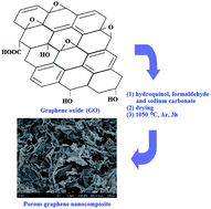
A novel three-dimensional nanostructured porous graphene nanocomposite was synthesized by sol–gel polymerization of hydroquinol (H) and formaldehyde (F) with sodium carbonate as a catalyst in graphene oxide (GO) suspension, followed by carbonization of HF and thermal reduction of GO to graphene at high temperature. The resulting material shows a BET surface area of 427 m2 g−1 and a total volume of 1.2764 cm3 g−1 with abundant mesopores. The porous graphene nanocomposite (HFG) can be used as anode for lithium ion batteries due to the porosity and thermal stability. Also, with the strong surface hydrophobicity, high mesopore ratio and pore volume, the HFG shows good absorption capacity for various organics, which makes the HFG a candidate for removal of organic contaminants from water.
Introduction
Graphene, a two-dimensional structured carbon a single atom thick, has sparked enormous interest in many fields such as nanoelectronics,1,2 sensors,3 catalysts,4,5 composites,6,7 batteries8,9 and supercapacitors,10–12 due to its unique chemical and physical properties.13,14 In particular, due to the high theoretical surface area and chemical stability, development of porous graphene for absorption of metal ions and organic contaminants, lithium storage and hydrogen storage have recently attracted extensive attention.15–19 Up to now, many kinds of methods were used to fabricate porous graphene materials.20–25 Among these approaches, the common one for preparation of porous graphene was directly using graphene nanosheets as building blocks by chemical or physical methods and has been well studied. Meanwhile, construction of porous graphene nanocomposites by using graphene nanosheets associating with other host materials such as polymers also has been proved as efficient route to develop novel porous graphene based materials.
As a representative nanoporous carbon, graphene aerogels have been reported to possess ultra-low-density, high electrical and conductivity, and large surface areas. Generally, graphene aerogel was prepared by pyrolysis of graphene oxide (GO) aerogel or other GO based composites.26–36 Nguyen et al. prepared graphene aerogel from GO aerogel using a hydrothermal method.31 Wang et al. synthesized graphene aerogel from GO and polyvinyl alcohol in water.34 Zhang et al.33 successfully prepared graphene aerogel by heating aqueous mixtures of GO and L-ascorbic acid. Worsley et al.35 reported the synthesis of ultra-low-density graphene aerogel based on resorcinol (R), formaldehyde (F) and GO that exhibit high electrical conductivities and large internal surface areas. As noted by Worsley et al., the RF plays a role of crosslinker in the graphene aerogel for the development of three-dimensional (3D) graphene network.35,36 As an analogue of RF, however, using of polymers prepared from hydroquinol and formaldehyde (HF) associating with GO for preparation of graphene-based porous network have never been investigated. From a material science standpoint, the development of novel precursors for preparation of porous graphene with open pore structures, good stabilities and large surface areas is of special interest.
In this work, we show that porous graphene nanocomposite (HFG) can also be obtained by sol–gel polymerization of HF with sodium carbonate as a catalyst in GO suspension, followed by carbonization of HF and thermal reduction of GO to graphene at high temperature. The resulting HFG shows a BET surface area of 427 m2 g−1 with a very high mesopore ratio and pore volume. We also investigate its electrochemical property and absorption for organic solvents. The findings of this study may offer a new possibility which would expect to extend the way for developing of new porous graphene materials by using HF as a precursor.
Experimental
Preparation of HF–GO composite
GO was prepared via a modified Hummers' method as literature and our previous work.37–40 The HF–GO composite was prepared using sol–gel method.35 In a typical experiment, GO dispersion (0.5437 g GO per 50 mL water) was added in a mixture of hydroquinol (1.235 g, 11.2 mmol), formaldehyde (1.791 g, 22.1 mmol) and sodium carbonate (5.95 mg, 0.056 mmol). Then the reaction mixture was kept at 85 °C for 72 h. The resulting composite was washed and purified by Soxhlet extraction (acetone) for 3 days.
Preparation of the HFG
The dried HF–GO composite was pyrolyzed at 1050 °C for 3 h in a tube furnace under a consecutive argon flow with a heating rate of 5 °C min−1.
Characterization
The morphologies of the resulting materials were examined by scanning electron microscopy (SEM, JSM-6701F, JEOL, Ltd.) and transmission electron microscopy (TEM, JEOL-2010). The porosity of materials was evaluated at 77 K using a pore and surface analyzer (Quantachrome, Autosorb-6B). X-Ray powder diffraction (XRD, D/Max-2400) measurements were performed on a Rigaku instrument with a Cu tube source and scans were taken from 2θ at 5° to 60°, step size 0.02°. Raman spectra were recorded using a micro-Ramam spectroscopy (JY-HR800, Jobin Yvon) with the excitation wavelength at 532 nm. The thermal properties of the samples were recorded by a thermogravimeter (TGA/DSC1, Mettle Toledo), and all of the measurements were carried out under nitrogen gas from room temperature to 1000 °C with a ramp rate of 5 °C min−1.
Electrochemical measurement
The electrochemical performance of the HFG was measured by CR2032 coin cells. The cells all comprised of an electrode, a microporous polypropylene separator (Celgard 2400) and lithium metal counter electrode. The electrode was prepared as follows. 75 wt% HFG sample was mixed with 15 wt% Super-P carbon black and aqueous 10 wt% LA132 binder (Chengdu Indigo power sources CO., Ltd.). Then the resulting mixture was spread on a copper foil to prepare discs with a diameter of 12 mm. The electrolyte was 1 mol L−1 LiPF6 solution of a mixture of ethylene carbonate, dimethyl carbonate and methyl-ethyl carbonate. The coin cells were assembled in an argon-filled glove box and cycled between 0 and 3 V (vs. Li+/Li) at room temperature using a CT2001A LAND battery testing system (Wuhan LAND Electronics Co., Ltd.).
Results and discussion
Details of the microstructure of the HFG are revealed by SEM and TEM. As shown in Fig. 1a, the HFG exhibits a 3D architecture with homogeneously interconnected pores. From the higher magnification of SEM image (Fig. 1b), a topographical micro/nanoporous structure of randomly oriented graphene sheets with wrinkled texture that are connecting with each other to form macropores is observed, which is similar to those seen in previous studies of 3D graphene networks.33 It is well known that organic sol–gel process involves the polymerization of organic precursors which can form highly cross-linked organic gels.35 When the organic precursors were added to GO suspension, polymerization occurred during the GO nanosheets and form junctions between adjacent GO nanosheets. After drying and pyrolysis, the organic polymer was converted to carbon and GO was reduced to graphene. Thus, carbonization of the organic polymer and reduction of the GO to graphene occurred simultaneously upon high temperature. Clearly, the carbon particles from the HF polymer effectively connect the graphene sheets into a 3D structure. The TEM image clearly reveals the structure of sheet-like graphene with wrinkling surfaces and folding edges and the existence of carbon particles. As shown in Fig. 1d, a single diffraction pattern obtained from the red marked region (Fig. 1c) exhibited the diffraction circles which reflected the overlapping monolayer graphene in the sample.
 |
| Fig. 1 (a and b) SEM images of the HFG. (c) TEM image of the HFG. (d) Scale bar: (a): 1 μm. (b): 100 nm. (c): 0.2 μm. (d) Diffraction pattern of the HFG. | |
The significant structural changes between GO and HFG were reflected in the XRD patterns. As shown in Fig. 2, GO as the start material shows a characteristic diffraction peak at around 12.3°, in accordance with previous work38 and corresponding to an interlayer distance of 0.73 nm. While for HFG, the peak at 12.3° disappeared, but a new and broad peak arose at around 24°, which is the characteristic diffraction peak for turbostratic carbon.41 Also, this peak appeared always be confirmed as the transformation from GO to graphene in other work.29,33 The interlayer spacing is decreased to 0.36 nm, which should be due to the removal of oxygen-containing groups in GO. These outcomes indicate the amorphous nature of HFG and thermal reduction of GO to graphene in the composite at high temperature.36
 |
| Fig. 2 XRD patterns of GO and HFG. | |
Raman analysis also reveals the transformation of structures for the samples. As shown in Fig. 3, compared with the Raman spectrum of GO which shows two characteristic peaks, one at 1356 cm−1 (D-band) corresponding to the sp2 carbon form,42 and the other at 1594 cm−1 (G-band) corresponding to the first-order scattering of the E2g mode,42 the D and G bonds also appeared in the Raman spectrum of the HFG, however, with an increased D/G intensity ratio, which suggests the thermal reduction and structural changes of GO to graphene in the HFG. Moreover, it has been reported that there is a strong G-band with no D-band for single-layer graphene.43 Thus, the presence of a prominent D-band in the HFG is most likely contributed to the inherent junctions in the network and remaining defects after the thermal reduction.36 This result was also accordance with the SEM and TEM observations.
 |
| Fig. 3 Raman spectra of GO and HFG. | |
Nitrogen adsorption–desorption isotherm of the HFG are shown in Fig. 4. The HFG displays a typical type-IV adsorption isotherms characteristic with H3 adsorption hysteresis loop at higher relative pressure. According to IUPAC classification, HFG is associated with mesoporous materials. Also, the initial region of the isotherms experienced a sharper rise both at low P/P0 (0–0.1), indicating the presence of micropores. From the isotherm, the Brunauer–Emmett–Teller (BET) surface area and micropore surface area derived using t-plot method were calculated to be 427 and 74 m2 g−1. The BET surface area is lower that the calculation value for a single layer of graphene, which should be contributed to the overlapping of graphene sheets and the existence of additional carbon particles in the resulting sample. The total pore volumes estimated from the amount of gas adsorbed (P/P0 = 0.97) was 1.2764 cm3 g−1. The micropore volume derived from the t-plot method is 0.0335 cm3 g−1. Pore size distribution of the sample shows that the pore size varies between 1.8 and 15 nm. These results suggest that the HFG consists micro- and mesopores (micropores ≤2 nm and mesopores 2–50 nm). And from the SEM observation of HFG (Fig. 1b), the mesopores could be generated by the wrinkled morphology of graphene sheets.33
 |
| Fig. 4 Nitrogen adsorption–desorption isotherm of the HFG, which was measured at 77 K. Inset is the pore size distributions of HFG. | |
The weight change of samples during thermal treatment process under N2 atmosphere is recorded by TGA measurement. As shown in Fig. 5, the weight loss of GO is about 40% below 250 °C, which is ascribed to the decomposition of oxygen functional groups. The HF–GO composite has a major mass loss with 28% at around 450 °C, due to the decomposition of polymer. However, for the HFG, there is no obvious weight change before 650 °C (only 5%), suggesting the better thermal stability compared with GO and the HF–GO composite.
 |
| Fig. 5 TGA curves of GO, HF–GO composite and the HFG. | |
Lithium ion batteries (LIBs) are the ideal energy storage device. The current development of high energy density LIBs has been achieved by the use of selected porous carbon.44,45 Considering the porous property, thermal stability and the unique electrochemical property of graphene nanosheets, the HFG could be used as anode materials for LIBs. To demonstrate the HFG as an anode material, electrochemical tests in coin cells was carried out. Fig. 6 shows the charge and discharge curves of the HFG at a constant current rate of 0.2 C between the voltage ranges from 0 V to 3.0 V. The initial discharge (lithium intercalation) capacity of the HFG is 1960 mA h g−1 and subsequent charge capacity (lithium deintercalation) is 437 mA h g−1, higher than reported hard carbons.46–48 The large irreversible specific capacity, also observed in other mesoporous carbon systems, should be contributed to the decomposition of electrolytes and solid electrolyte interphase (SEI) layers formation on the surface of HFG.49–51 As shown in SEM images (Fig. 1) and pore size distribution (Fig. 3), the abundant mesopores would adsorb a great amount of electrolyte, which results in the rapid deposition of the SEI layer on the electrode surface.52 On the other hand, the structural defects introduced during the reduction of GO with oxygen containing functional groups on the surface of graphene also contribute to the irreversible capacity.53 The previous work has proved that porous structure is beneficial for improving the rate performance of LIBs.54–56 Fig. 6 also shows the second, third, fifth and tenth charge/discharge voltage curves in which the capacity slowly decreases indicating the good cycling performance of HFG. The discharge/charge capacity cycles of HFG electrode at enhanced rates is also shown in Fig. 7. The HFG electrode has a discharge capacity of 311.1, 245.2, 185, 151.1, 141.7, 119.4, 104.1, 86.8, 72.6 and 73.7 mA h g−1 during the tenth cycle at 0.2, 0.5, 1, 2, 3, 5, 10, 20, 40 and 60 C, respectively. When the rate decreasing from 60 C to 0.2 C, the capacity of the HFG electrode is 355.5 mA h g−1, which is higher than its original value of 311.1 mA h g−1. This is different from the previous non-graphitic carbons which exhibit a continuous and progressive decay in capacity upon cycling.57 Such good rate performance of the HFG electrode should be contributed to its homogeneous porosity and the unique ultrathin layer structure of graphene nanosheets in which lithium ion diffusion ability can be greatly enhanced, thus making the HFG be a candidate as lithium ion storage material even at high charge/discharge rates.
 |
| Fig. 6 Galvanostatic discharge (Li insertion, voltage decreases)/charge (Li extraction, voltage increases) curves of the HFG sample cycled at a rate of 0.2 C (the electrodes are cycled in a 1 M solution of LiPF6 in a mixture of ethylene carbonate, dimethyl carbonate and methyl-ethyl carbonate with a volume ratio of 1 : 1 : 1). | |
 |
| Fig. 7 Cycling performance of the HFG sample at different cycling rates (0.2–60 C). | |
On the other hand, with increasing attention on the global scale of severe water pollution, graphene materials with exciting hydrophobic properties have been reported for removal of oil spills or organic contaminants from water. In our previous work, we also synthesized porous graphene with 3D structure using a hard template method, which shows good separation and selective absorption of organics from water.16 Thus, in this work, we also investigate the absorption capacity of HFG for organic solvents. As shown in Fig. 8 inset, the HFG show good surface wettability with a water contact angle (CA) of 148 ± 2° and an oil CA of nearly 0°. This finding suggests that the resulting HFG can absorb organic solvents with high selectivity from water. The efficiency of organics and oils absorption can be referred to as weight gain which was defined as the weight of absorbed organic per unit weight of dried HFG. As shown in Fig. 8, different organic solvents were used to evaluate the absorption capacity of HFG. The HFG shows an absorption capacity ranging from 6.39 g g−1 to 25.00 g g−1. For example, the HFG absorbed nitrobenzene, DMSO and chlorobenzene at rates of 25.00×, 23.69× and 19.33×, respectively. The absorption capacity is much higher than the reported commercial activated carbon,58 which should be contributed to the high mesopore ratio and pore volume of the HFG. With the value, the HFG can be candidate for removal of organic contaminants from water.
 |
| Fig. 8 Absorption capacity of the hydrophobic HFG for various organic solvents. Inset is the water and kerosene CA measurement. | |
Conclusions
In this study, three-dimensional nanostructured porous graphene nanocomposite was synthesized based on sol–gel polymerization of hydroquinol and formaldehyde in GO suspension and thermal reduction of GO to graphene at high temperature. The resulting material shows a BET surface area of 427 m2 g−1 and a total volume of 1.2764 cm3 g−1 with abundant mesopores. When the porous graphene nanocomposite was employed as anode for LIBs, the electrochemical performances showed good rate performance and enhancement of cycling durability. Also, absorption test results indicated the efficient absorption of oils and organic solvents for the HFG, which makes the HFG a candidate for removal of organic contaminants from water.
Acknowledgements
This work was supported by the National Natural Science Foundation of China (grant no. 51263012, 51262019) and Gansu Provincial Science Fund for Distinguished Young Scholars (grant no. 1308RJDA012).
Notes and references
- M. Freitag, Nat. Nanotechnol., 2008, 3, 455–457 CrossRef CAS PubMed.
- Y. Xuan, Y. Q. Wu, T. Shen, M. Qi, M. A. Capano, J. A. Cooper and P. D. Ye, Appl. Phys. Lett., 2008, 92, 013101 CrossRef PubMed.
- M. Pumera, Chem. Rec., 2009, 9, 211–223 CrossRef CAS PubMed.
- I. V. Lightcap, T. H. Kosel and P. V. Kamat, Nano Lett., 2010, 10, 577–583 CrossRef CAS PubMed.
- Y. Li, H. Wang, L. Xie, Y. Liang, G. Hong and H. Dai, J. Am. Chem. Soc., 2011, 133, 7296–7299 CrossRef CAS PubMed.
- S. Stankovich, D. A. Dikin, G. H. Dommett, K. M. Kohlhaas, E. J. Zimney, E. A. Stach, R. D. Piner, S. T. Nguyen and R. S. Ruoff, Nature, 2006, 442, 282–286 CrossRef CAS PubMed.
- D. Zhou, T.-L. Zhang and B.-H. Han, Microporous Mesoporous Mater., 2013, 165, 234–239 CrossRef CAS PubMed.
- P. Guo, H. Song and X. Chen, Electrochem. Commun., 2009, 11, 1320–1324 CrossRef CAS PubMed.
- G. Zhou, D.-W. Wang, F. Li, L. Zhang, N. Li, Z.-S. Wu, L. Wen, G. Q. Lu and H.-M. Cheng, Chem. Mater., 2010, 22, 5306–5313 CrossRef CAS.
- A. Dale, Chem. Commun., 2012, 48, 1425–1427 RSC.
- J. J. Yoo, K. Balakrishnan, J. Huang, V. Meunier, B. G. Sumpter, A. Srivastava, M. Conway, A. L. Mohana Reddy, J. Yu and R. Vajtai, Nano Lett., 2011, 11, 1423–1427 CrossRef CAS PubMed.
- Z. Fan, Q. Zhao, T. Li, J. Yan, Y. Ren, J. Feng and T. Wei, Carbon, 2012, 50, 1699–1703 CrossRef CAS PubMed.
- A. K. Geim and K. S. Novoselov, Nat. Mater., 2007, 6, 183–191 CrossRef CAS PubMed.
- K. S. Novoselov, A. K. Geim, S. Morozov, D. Jiang, Y. Zhang, S. Dubonos, I. Grigorieva and A. Firsov, Science, 2004, 306, 666–669 CrossRef CAS PubMed.
- P. Reunchan and S.-H. Jhi, Appl. Phys. Lett., 2011, 98, 093103 CrossRef PubMed.
- Z. L. Fan, X. J. Qin, H. X. Sun, Z. Q. Zhu, C. J. Pei, W. D. Liang, X. M. Bao, J. An, P. Q. La and A. Li, ChemPlusChem, 2013, 78, 1282–1287 CrossRef CAS.
- J. Xiao, D. Mei, X. Li, W. Xu, D. Wang, G. L. Graff, W. D. Bennett, Z. Nie, L. V. Saraf, I. A. Aksay, J. Liu and J.-G. Zhang, Nano Lett., 2011, 11, 5071–5078 CrossRef CAS PubMed.
- Z. Fan, J. Yan, G. Ning, T. Wei, L. Zhi and F. Wei, Carbon, 2013, 60, 558–561 CrossRef CAS PubMed.
- S. Nardecchia, D. Carriazo, M. L. Ferrer, M. C. Gutierrez and F. del Monte, Chem. Soc. Rev., 2013, 42, 794–830 RSC.
- X. Li, T. Zhao, Q. Chen, P. Li, K. Wang, M. Zhong, J. Wei, D. Wu, B. Wei and H. Zhu, Phys. Chem. Chem. Phys., 2013, 15, 17752–17757 RSC.
- X. Li, T. Zhao, K. Wang, Y. Yang, J. Wei, F. Kang, D. Wu and H. Zhu, Langmuir, 2011, 27, 12164–12171 CrossRef CAS PubMed.
- Q. Wang, J. Yan, Y. Wang, T. Wei, M. Zhang, X. Jing and Z. Fan, Carbon, 2014, 67, 119–127 CrossRef CAS PubMed.
- R. Yue, F. Ren, C. Wang, J. Xu and Y. Du, RSC Adv., 2014, 4, 500–504 RSC.
- R. Kumar, V. M. Suresh, T. K. Maji and C. N. R. Rao, Chem. Commun., 2014, 50, 2015–2017 RSC.
- Y. Li, Q. Zhang, J. Zhu, X.-L. Wei and P. K. Shen, J. Mater. Chem. A, 2014, 2, 3163–3168 CAS.
- F. Meng, X. Zhang, B. Xu, S. Yue, H. Guo and Y. Luo, J. Mater. Chem., 2011, 21, 18537–18539 RSC.
- M. Chen, C. Zhang, X. Li, L. Zhang, Y. Ma, L. Zhang, X. Xu, F. Xia, W. Wang and J. Gao, J. Mater. Chem. A, 2013, 1, 2869–2877 CAS.
- X. Wu, J. Zhou, W. Xing, G. Wang, H. Cui, S. Zhuo, Q. Xue, Z. Yan and S. Z. Qiao, J. Mater. Chem., 2012, 22, 23186–23193 RSC.
- W. Chen and L. Yan, Nanoscale, 2011, 3, 3132–3137 RSC.
- H.-P. Cong, X.-C. Ren, P. Wang and S.-H. Yu, ACS Nano, 2012, 6, 2693–2703 CrossRef CAS PubMed.
- S. T. Nguyen, H. T. Nguyen, A. Rinaldi, N. P. Nguyen, Z. Fan and H. M. Duong, Colloids Surf., A, 2012, 414, 352–358 CrossRef CAS PubMed.
- Y. Lin, G. J. Ehlert, C. Bukowsky and H. A. Sodano, ACS Appl. Mater. Interfaces, 2011, 3, 2200–2203 CAS.
- X. Zhang, Z. Sui, B. Xu, S. Yue, Y. Luo, W. Zhan and B. Liu, J. Mater. Chem., 2011, 21, 6494–6497 RSC.
- J. Wang and M. Ellsworth, ECS Trans., 2009, 19, 241–247 Search PubMed.
- M. A. Worsley, P. J. Pauzauskie, T. Y. Olson, J. Biener, J. H. Satcher Jr and T. F. Baumann, J. Am. Chem. Soc., 2010, 132, 14067–14069 CrossRef CAS PubMed.
- M. A. Worsley, T. Y. Olson, J. R. Lee, T. M. Willey, M. H. Nielsen, S. K. Roberts, P. J. Pauzauskie, J. Biener, J. H. Satcher Jr and T. F. Baumann, J. Phys. Chem. Lett., 2011, 2, 921–925 CrossRef CAS.
- W. S. Hummers Jr and R. E. Offeman, J. Am. Chem. Soc., 1958, 80, 1339 CrossRef.
- Z.-Q. Zhu, H.-X. Sun, X.-J. Qin, L. Jiang, C.-J. Pei, L. Wang, Y.-Q. Zeng, S.-H. Wen, P.-Q. La and A. Li, J. Mater. Chem., 2012, 22, 4811–4817 RSC.
- Z. Q. Zhu, H. X. Sun, G. X. Li, W. D. Liang, X. M. Bao, J. An, P. Q. La, J. F. Dai and A. Li, J. Appl. Polym. Sci., 2013, 129, 2328–2334 CrossRef CAS.
- S. Stankovich, R. D. Piner, S. T. Nguyen and R. S. Ruoff, Carbon, 2006, 44, 3342–3347 CrossRef CAS PubMed.
- Z. Yang, Y. Xia and R. Mokaya, J. Am. Chem. Soc., 2007, 129, 1673–1679 CrossRef CAS PubMed.
- F. Tuinstra and J. L. Koenig, J. Chem. Phys., 1970, 53, 1126 CrossRef CAS PubMed.
- D. Graf, F. Molitor, K. Ensslin, C. Stampfer, A. Jungen, C. Hierold and L. Wirtz, Nano Lett., 2007, 7, 238–242 CrossRef CAS PubMed.
- B. Xu, L. Shi, X. Guo, L. Peng, Z. Wang, S. Chen, G. Cao, F. Wu and Y. Yang, Electrochim. Acta, 2011, 56, 6464–6468 CrossRef CAS PubMed.
- E. Unur, S. Brutti, S. Panero and B. Scrosati, Microporous Mesoporous Mater., 2013, 174, 25–33 CrossRef CAS PubMed.
- J. Wang, J.-L. Liu, Y.-G. Wang, C.-X. Wang and Y.-Y. Xia, Electrochim. Acta, 2012, 74, 1–7 CrossRef CAS PubMed.
- J.-H. Lee, H.-Y. Lee, S.-M. Oh, S.-J. Lee, K.-Y. Lee and S.-M. Lee, J. Power Sources, 2007, 166, 250–254 CrossRef CAS PubMed.
- H. Fujimoto, K. Tokumitsu, A. Mabuchi, N. Chinnasamy and T. Kasuh, J. Power Sources, 2010, 195, 7452–7456 CrossRef CAS PubMed.
- J. Liu, G. Cao, Z. Yang, D. Wang, D. Dubois, X. Zhou, G. L. Graff, L. R. Pederson and J.-G. Zhang, ChemSusChem, 2008, 1, 676–697 CrossRef CAS PubMed.
- B. Guo, X. Wang, P. F. Fulvio, M. Chi, S. M. Mahurin, X.-G. Sun and S. Dai, Adv. Mater., 2011, 23, 4661–4666 CrossRef CAS PubMed.
- K. T. Lee, J. C. Lytle, N. S. Ergang, S. M. Oh and A. Stein, Adv. Funct. Mater., 2005, 15, 547–556 CrossRef CAS.
- X. Zhou, J. Tang, J. Yang, J. Xie and B. Huang, J. Mater. Chem. A, 2013, 1, 5037–5044 CAS.
- Y. Fang, Y. Lv, R. Che, H. Wu, X. Zhang, D. Gu, G. Zheng and D. Zhao, J. Am. Chem. Soc., 2013, 135, 1524–1530 CrossRef CAS PubMed.
- Y. Zhu, S. Murali, M. D. Stoller, K. J. Ganesh, W. Cai, P. J. Ferreira, A. Pirkle, R. M. Wallace, K. A. Cychosz, M. Thommes, D. Su, E. A. Stach and R. S. Ruoff, Science, 2011, 332, 1537–1541 CrossRef CAS PubMed.
- Y. Zhai, Y. Dou, D. Zhao, P. F. Fulvio, R. T. Mayes and S. Dai, Adv. Mater., 2011, 23, 4828–4850 CrossRef CAS PubMed.
- C. Liang, Z. Li and S. Dai, Angew. Chem., Int. Ed., 2008, 47, 3696–3717 CrossRef CAS PubMed.
- P. Adelhelm, Y. S. Hu, L. Chuenchom, M. Antonietti, B. M. Smarsly and J. Maier, Adv. Mater., 2007, 19, 4012–4017 CrossRef CAS.
- H. Sun, A. Li, Z. Zhu, W. Liang, X. Zhao, P. La and W. Deng, ChemSusChem, 2013, 6, 1057–1062 CrossRef CAS PubMed.
|
This journal is © The Royal Society of Chemistry 2014 |
Click here to see how this site uses Cookies. View our privacy policy here.