A Se/C composite as cathode material for rechargeable lithium batteries with good electrochemical performance

Lili Liu, Yuyang Hou, Yaqiong Yang, Minxia Li, Xiaowei Wang and Yuping Wu*
New Energy and Materials Laboratory (NEML), Department of Chemistry & Shanghai Key Laboratory of Molecular Catalysis and Innovative Materials, Fudan University, Shanghai 200433, China. E-mail: wuyp@fudan.edu.cn; Fax: +86-21-55664223

Received 29th December 2013 , Accepted 20th January 2014

First published on 22nd January 2014


Abstract

A Se/C composite was prepared by a simple combination method of ball milling and low temperature treatment as a cathode material for Li–Se rechargeable batteries. It was characterized by X-ray diffraction (XRD), scanning electron microscopy (SEM) and transmission electron microscopy (TEM). Its electrochemical performance as a cathode material for lithium rechargeable batteries was tested by cyclic voltammetry (CV) and capacity measurements. Rate capacity and cycling performance of the as-prepared product are very satisfactory. Even at a current density of 500 mA g−1, the composite can deliver a capacity of 187 mA h g−1. The main reason is that the high conductivity of carbon decreases its charge transfer resistance and effectively suppresses the dissolution of oxidation products from the composite cathode.

1. Introduction

The widespread application of mobile devices and potential use in electric vehicles has motivated scientific and technological efforts dedicated to improving existing rechargeable battery systems and to developing new electrode reactions and materials.1 Currently, among all the known battery systems, lithium–sulfur batteries seem to have attracted more attention compared with the traditional lithium ion batteries because of their high theoretical capacity (1675 mA h g−1) and energy density (2600 W h kg−1).2,3 However, the poor electrical conductivity of S and the solubility of intermediary polysulfide species during cycling seriously impede their commercial applications.3,4

In order to tackle the above restrictions, exploring novel electrode materials seems to be an imperative strategy.4–7 Selenium, owing to its similar chemical properties with sulfur, has been put forward as electrode material with great potential because of its higher electronic conductivity (approximately 20 orders of magnitude greater than that of S) and higher output voltages (at least 0.5 V higher for Li–S).4,5 Similar to Li–S battery, Li–Se battery is based on the reversible oxidization–reduction reaction between selenium and lithium. As a cathode material for rechargeable lithium battery, results from Amine's group4 indicate that although the charge potential can be up to 4.6 V (vs. Li+/Li) and the cycling performance is stable, it still suffers rather low columbic efficiency and capacity fading which are caused by the redox shuttle effect.8 Recently, new studies9 on the Se-based material show low voltage plateau during charge process which is much different from the other reports.4,5 Since many scientists have successfully tried using conducting materials such as carbon,2c,10 graphenes11 and polypyrrole12 to activate the electrochemical performance of the electrode materials because that these materials not only improve the electronic conductivity but also maintain the structural integrity of the electrode material. These results suggest that mixing with conductive material is a good strategy for inhibiting the redox shuttle effect and thus improving the electrochemical performance of selenium electrode.

Here we report a Se/C composite prepared by a simple process as a cathode material for rechargeable lithium battery. The introduced carbon material effectively suppresses the dissolution of oxidation products of Se and greatly improves the electrochemical performance of the selenium cathode.

2. Experimental

2.1 Synthesis of Se/C composite

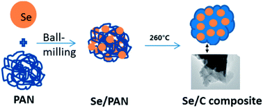
All the reagents were analytical grade. A certain amount of commercial Se particles and PAN (polyacrylonitrile) were loaded into a 50 ml steel bowl containing 18 hardened steel balls in a diameter of 10 mm. After high-energy ball-milling at a rotation rate of 400 rpm for 12 h on a planetary ball mill, the obtained uniform mixture was calcined at 260 °C for 12 h at a heating rate of 2 °C min−1 under flowing Ar (99.99%, 200 ml min−1) to produce a Se/C composite with carbon in the internal and at the external surfaces of the Se nanoparticles. This simple preparation procedure is schematically illustrated in Scheme 1. The commercial Se particles, denoted as CP-Se, were used as a control.
image file: c3ra48034h-s1.tif
Scheme 1 Schematic illustration for the preparation process of Se/C composite.

2.2 Characterization and electrochemical evaluation

The following measurements were performed at room temperature. The crystal structures of the prepared Se/C composite and CP-Se were characterized by X-ray powder diffraction (XRD) using a Bruker Analytical X-ray System with CuKα radiation source filtered by a Ni thin plate. Scanning electron micrograph (SEM) and transmission electron micrograph (TEM) were obtained on a Philips XL30 scanning electron microscope and a JEOL JEM-2010 transmission electron microscope, respectively. Raman spectra was collected using a Raman spectrometer (JobinYvon HR800) employing a 10 mW helium/neon laser at 632.8 nm. X-ray photoscopic (XPS) spectra were obtained on a spectrometer (Perkin Elmer PHI-5000C) with electron combination energy corrected by using graphite as a reference, whose combination energy of C1s was designated at 284.60 eV.

Coin-type half-cells were assembled for evaluating the electrochemical performance of the as-prepared Se/C composite and the commercial Se. Commercial Se and the as-prepared Se/C nanocomposite were mixed with acetylene black (AB) and poly(vinylidene fluoride) (PVDF) at a weight ratio of 8[thin space (1/6-em)]:[thin space (1/6-em)]1[thin space (1/6-em)]:[thin space (1/6-em)]1with N-methyl-pyrrolidone as a solvent. The mixture was coated on aluminium foil, then dried at room temperature and cut into small pellets with weight of about 2 mg for each pellet. Then the pellets were dried at 120 °C overnight in vacuum. Finally, button-type model cells were assembled in a glove box with the pellets as the working electrode, lithium foil as the counter and reference electrode, porous Celgard 2400 as the separator, and a standard 1.0 mol L−1 LiPF6 solution in a mixture of EC (ethylene carbonate)–DMC (dimethyl carbonate)–DEC (diethyl carbonate) (1[thin space (1/6-em)]:[thin space (1/6-em)]1[thin space (1/6-em)]:[thin space (1/6-em)]1, v/v/v) as the electrolyte. Electrochemical performance of both commercial Se and Se/C composite were carried out using a LANDct3.3 battery tester at different rates between 0.8 and 4.3 V vs. Li+/Li.

3. Results and discussion

The composition and structure of the Se/C composite and CP-Se were characterized by X-ray diffraction (XRD) and Raman spectroscopy (see Fig. 1). In their XRD patterns (Fig. 1a), there are several peaks at 23.5° (100), 29.7° (101), 41.3° (110), 43.6° (102), 45.4° (111), 51.8° (201), 55.7° (112), and 61.5° (202), which are in good accordance with the diffraction peaks of the trigonal phase of selenium (JCPDS 06-0362).13,14 However, for the Se/C composite, no evident peaks for carbon or graphite can be observed. This suggests that the carbon exists mostly in amorphous state due to the heat-treatment at low temperature. For the Se/C composite, two characteristic bands are observed in the Raman spectrum of carbon: the one centred at 1343 cm−1 (D band) is attributed to local defects and disorder area in the carbon, and the other at 1572 cm−1 (G band) can be assigned to the sp2 graphitized structure.11a It is clear that the intensity of the D band is much stronger than that of the G-band, indicating that the carbon is mostly amorphous,11a,15 which is consistent with the above XRD patterns. However, the Raman spectrum of CP-Se reveals no characteristic bands of carbon. For the two materials, the resonance peaks at 233 cm−1 are a characteristic of A1 and E modes stretching of the trigonal selenium14,16 while the peaks at 460 cm−1 can be attributed to the second-order spectra of the trigonal selenium.16
image file: c3ra48034h-f1.tif
Fig. 1 (a) X-ray diffraction patterns and (b) Raman spectra of the Se/C composite and CP-Se.

Fig. 2 illustrates the SEM and TEM micrographs of the Se/C composite. For comparison, the SEM micrograph of the CP-Se is shown in Fig. S1 in the ESI. The Se/C composite shows morphology of particles with Se and C connecting with each other closely, which can be proofed by the TEM micrograph (Fig. 2b). In Fig. 2a, it can be observed that the Se particle is embedded by the carbon material transformed from the PAN at 260 °C under Ar atmosphere. The EDX result shows that the weight ratio of the Se element in the composite is 56.4%.


image file: c3ra48034h-f2.tif
Fig. 2 (a) SEM and (b) TEM micrographs of the Se/C composite. trigonal selenium.17

Cyclic voltammograms at the scan rate of 0.1 mV s−1 in the potential range 0.8–4.3 V in the initial two scans of the as-prepared Se/C composite and the CP-Se are shown in Fig. 3a. It can be clearly observed that both electrodes show one pair of redox peaks: 1.6/4.1 V (vs. Li+/Li) for the CP-Se while 1.6/3.9 V (vs. Li+/Li) for the Se/C composite. In the first cycle, the peak located at 1.6 V corresponds to the Se reduction process and the peaks situated at 3.9 or 4.1 V belongs to the minimal structural changes to the electrode, not associated with an electrochemical reaction of the electrode materials.4,5 So, the CP-Se electrode only shows a single reduction peak at 1.6 V with the absence of no oxidation peak during the successive scanning process. Whereas, as for the Se/C composite electrode, an oxidation peak could be clearly seen in the CV plot at about 2.1 V, which can be ascribed to the Se oxidation. The above result well confirms that the Se/C electrode can partially activate the redox process and reduce the overpotential.12f


image file: c3ra48034h-f3.tif
Fig. 3 (a) Cyclic voltammograms at the scan rate of 0.1 mV s−1 in the voltage range 0.8–4.3 V and (b) Nyquist plots of the Se/C composite and CP-Se.

Fig. 3b shows typical Nyquist plots of the Se/C composite and CP-Se. It is obvious that the charge transfer resistance (Rct) relating to the electrochemical activities of the Se/C composite is significantly decreased compared with that of the CP-Se. This can be evidently ascribed the electronic conductive network of the carbon from the decomposition of PAN at low temperature though it is amorphous.

Fig. 4a displays the discharge/charge curves in the first and the 10th cycles of the Se/C composite and the CP-Se in the voltage range between 0.8 and 4.3 V at the current density of 100 mA g−1. For both materials, the initial discharge involves one well-defined plateau indicative of the Li+ ion insertion (reaction of Li+ ions with Se via getting electrons). During the successive charge process, the prepared Se/C composite shows two plateaus (at 2.0 and 3.9 V) corresponding to the electrochemical reaction (conversion of Li2Se into Se and Li+ ions via losing electrons) and the structural change of the Se,4 respectively. The charge and discharge phenomenon is similar with the reported data4,5 but different with the other studies.9 It is notable that the Coulombic efficiency in this work is much larger than that in the previous report.4 Unlike the Se/C composite, the CP-Se shows only one plateau. All the phenomena illustrated above are in good accordance with the above results from the CV test. Obviously, the Se/C composite can deliver a high capacity than that of the CP-Se electrode. After 10 cycles, the prepared composite can maintain a discharge capacity of 244 mA h g−1, much larger than that of the CP-Se. There is no doubt that the addition of carbon in the composite creates a conducting network between the Se particles, resulting in a reduced contact resistance and an increase in the reaction area and capacity.2c,10,12 The voltage profiles at different cycle number are shown in Fig. 4b. It can be clearly observed that the difference between the charge and discharge voltages for the Li–Se–C cells is reduced with the increase of the cycle number, especially in the case of the voltage curves in the 30th cycle. Compared with the data presented by Amine's group,4,9a probably there are several factors accounting for the voltage difference. Firstly, electronic conductivity of carbon materials from the pyrolysis of polymers at low temperature (260 °C) is not high as carbon nanotubes, which will cause large polarization. Secondly, ether-based electrolyte can positively effect electrochemical performance compared with the carbonate-based electrolyte which is used in our work. In addition, the as-prepared Se/C composite also present better cycling performance compared with the CP-Se. As shown in Fig. 4c, although the capacities in the first several cycles show a little fluctuation, they do not suffer drastic capacity fading. After 20 cycles, the Se/C composite can still maintain a discharge capacity of 269.5 mA h g−1, but the CP-Se only delivers a discharge capacity below 60 mA h g−1. From the 30 to 50 cycles, it presents a relatively stable charge and discharge capacity as well as higher Coulombic efficiency, which is due to that the Se particle is embedded into the carbon material.


image file: c3ra48034h-f4.tif
Fig. 4 (a) Discharge/charge curves in the first and 10th cycles of the CP-Se and the Se/C composite, (b) discharge/charge curves in the first, 10th, 20th and 30th cycles of the Se/C composite, (c) cycling performance at the current density of 100 mA g−1 and (d) rate capability at different current densities for the Se/C composite and the CP-Se in the voltage range between 0.8 and 4.3 V.

To determine the rate performance of the as-prepared Se/C composite, the cathodes were tested galvanostatically at different current densities ranging from 50 mA g−1 to 500 mA g−1 (Fig. 4d). The Se/C composite exhibits obviously an improved electrochemical performance. A high discharge capacity of 348 mA h g−1 was obtained at the current density of 50 mA g−1, while that for the CP-Se is only 157 mA h g−1. When the current density is increased to 500 mA g−1, the Se/C composite can still keep a discharge capacity of 187 mA h g−1. In contrast, the electrochemical performance of the CP-Se is poor. At 500 mA g−1, its reversible capacity is almost 0. The better rate capability of the Se/C composite can be attributed to the improved conductivity of the introduced carbon matrix.

Fig. 5 shows the XPS spectra of Li1s after the 5th discharge to 0.8 V. For both electrodes, the fitted curves clearly show an energy peak positioned at 54.7 eV, which corresponds to the component of the Li2Se.12f The peak at 58.6 eV may refer to the Li1s of LiPF6 from the electrolyte, which is not washed totally away. For the Se/C electrode, the peak at 54.7 eV is much stronger and sharper than that of CP-Se electrode, indicating a larger intensity of the Li2Se in the electrode. This indicates that there is a deeper reaction between the Li+ ion and Se, which is the reason of higher capacity for the Se/C composite. At the same time, it also means a less quantity of Li2Se dissolving into the electrolyte. All this can be attributed to the introduced carbon material closely on the inner structure and external surface of the Se particles. The above illustration is consistent with the result of Fig. S2 in the ESI. After dismantling the cells of the two materials, the colour of the Celgard membrane for the Se/C cell is still white, while that for the CP-Se cell is red which is caused by the dissolution of the products such as LixSe, which is similar to dissolvable LixS.2a,18


image file: c3ra48034h-f5.tif
Fig. 5 XPS spectra of Li1s in the Se/C composite and the CP-Se after the 5th discharge to 0.8 V.

It is known that the electronic conductivity of carbon materials from the pyrolysis of polymers at low temperature (260 °C) is not high. In this case, the carbon from the pyrolysis of PAN at such a low temperature can present good conductivity is due to its unique structure, which can cyclize at 200–250 °C to get a net-like polymers.19 When some small molecules are given off at this temperature, a graphene-like structure is achieved. Of course, its electronic conductivity is not very high. The main reason is that the temperature should not be too much above the melting point of Se (about 217 °C) in order to keep Se in the carbon. If carbon materials of higher conductivity are used to prepare a Se/C composite, its electrochemical performance will be better.

4. Conclusions

In summary, we have developed an Se/C composite by a very simple method as a cathode for rechargeable lithium battery with an excellent rate capability and good cycling performance. Even at a current density of 500 mA g−1, the composite can deliver a discharge capacity of 187 mA h g−1. The main reason is that due to the good electronic conductivity of carbon can increase the reaction depth and effectively suppress the dissolution of oxidation product from the cathode. The unique characteristics demonstrate that Se-based materials will be another promising cathode candidate for the future rechargeable lithium batteries.

Acknowledgements

Financial support from the International Science & Technology Cooperation Program of China (2010DFA61770), the NSFC (21073046) and STCSM (12JC1401200) is greatly appreciated.

Notes and references

  1. (a) F. Y. Cheng, J. Liang, Z. L. Tao and J. Chen, Adv. Mater., 2011, 23, 1695 CrossRef CAS PubMed; (b) Y. P. Wu, X. Y. Yuan, C. Dong and J. Y. Duan, Lithium ion batteries: Applications and Practice, Chemical Industry Press, Beijing, 2nd edn, 2012 Search PubMed; (c) A. R. Armstrong, M. Holzapfel, P. Novák, J. C. S. Ohnson, S. H. Kang, M. M. Thackeray and P. G. Bruce, J. Am. Chem. Soc., 2006, 128, 8694 CrossRef CAS PubMed; (d) Y. Yang, G. Y. Zheng and Y. Cui, Energy Environ. Sci., 2013, 6, 1552 RSC; (e) X. J. Wang, Y. Y. Hou, Y. S. Zhu, Y. P. Wu and R. Holze, Sci. Rep., 2013, 3, 1401 CAS; (f) X. J. Wang, Q. T. Qu, Y. Y. Hou, F. X. Wang and Y. P. Wu, Chem. Commun., 2013, 49, 6179 RSC.
  2. (a) M. Nagao, A. Hayashi and M. Tatsumisago, J. Mater. Chem., 2012, 22, 10015 RSC; (b) F. Wu, J. Z. Chen, L. Li, T. Zhao and R. J. Chen, J. Phys. Chem. C, 2011, 115, 24411 CrossRef CAS; (c) J. C. Guo, Y. H. Xu and C. S. Wang, Nano Lett., 2011, 11, 4288 CrossRef CAS PubMed; (d) L. F. Xiao, Y. L. Cao, J. Xiao, B. Schwenzer, M. H. Engelhard, L. V. Saraf, Z. M. Nie, G. J. Exarhos and J. Liu, Adv. Mater., 2012, 24, 1176 CrossRef CAS PubMed; (e) X. Y. Tao, F. Chen, Y. Xia, H. Huang, Y. P. Gan, X. R. Chen and W. K. Zhang, Chem. Commun., 2013, 49, 4513 RSC.
  3. X. L. Ji, K. T. Lee and L. F. Nazar, Nat. Mater., 2009, 8, 500 CrossRef CAS PubMed.
  4. A. Abouimrane, D. Dambournet, K. W. Chapman, P. J. Chupas, W. Weng and K. Amine, J. Am. Chem. Soc., 2012, 134, 4505 CrossRef CAS PubMed.
  5. L. L. Liu, Y. Y. Hou, S. Y. Xiao, Z. Chang, Y. Q. Yang and Y. P. Wu, Chem. Commun., 2013, 49, 11515 RSC.
  6. C. P. Yang, S. Xin, Y. X. Yin, H. Ye, J. Zhang and Y. G. Guo, Angew. Chem., Int. Ed., 2013, 125, 8521 CrossRef.
  7. (a) Y. F. Shi, Y. Wan, R. L. Liu, B. Tu and D. Y. Zhao, J. Am. Chem. Soc., 2007, 129, 9522 CrossRef CAS PubMed; (b) Y. F. Shi, C. X. Hua, B. Li, X. P. Fang, C. H. Yao, Y. C. hang, Y. S. Hu, Z. X. Wang, L. Q. Chen, D. Y. Zhao and G. D. Stucky, Adv. Funct. Mater., 2013, 23, 1832 CrossRef CAS; (c) F. X. Wang, S. Y. Xiao, Z. Chang, Y. Q. Yang and Y. P. Wu, Chem. Commun., 2013, 49, 9209 RSC.
  8. B. M. L. Rao and J. A. Shrophire, J. Electrochem. Soc., 1981, 128, 942 CrossRef CAS PubMed.
  9. (a) Y. J. Cui, A. Abouimrane, J. Lu, T. Bolin, Y. Ren, W. Weng, C. J. Sun, V. A. Maroni, S. M. Heald and K. Amine, J. Am. Chem. Soc., 2013, 135, 8047 CrossRef CAS PubMed; (b) C. Luo, Y. H. Xu, Y. H. Liu, S. Y. Zheng, Y. Liu, A. Langrock and C. S. Wang, ACS Nano, 2013, 7, 8003 CrossRef CAS PubMed.
  10. (a) L. J. Fu, L. C. Yang, Y. Shi, B. Wang and Y. P. Wu, Microporous Mesoporous Mater., 2009, 117, 515 CrossRef CAS PubMed; (b) C. F. Zhang, H. B. Wu, C. Z. Yuan, Z. P. Guo and X. W. Lou, Angew. Chem., Int. Ed., 2012, 51, 9592 CrossRef CAS PubMed; (c) L. C. Yang, L. L. Liu, Y. S. Zhu, X. J. Wang and Y. P. Wu, J. Mater. Chem., 2012, 22, 13148 RSC; (d) G. X. Wang, H. Liu, J. Liu, S. Z. Qiao, G. Q. M. Lu, P. Munroe and H. Ahn, Adv. Mater., 2010, 22, 4944 CrossRef CAS PubMed; (e) Y. Y. Hou, X. J. Wang, Y. S. Zhu, C. L. Hu, Z. Chang, Y. P. Wu and R. Holze, J. Mater. Chem. A, 2013, 1, 14713 RSC; (f) Y. S. Su and A. Manthiram, Chem. Commun., 2012, 48, 8817 RSC; (g) S. Dorfler, M. Hagen, H. Althues, J. Tubke, S. Kaskel and M. J. Hoffmann, Chem. Commun., 2012, 48, 4097 RSC.
  11. (a) Y. Shi, S. L. Chou, J. Z. Wang and Y. P. Wu, J. Mater. Chem., 2012, 22, 16465 RSC; (b) D. Wang, D. Choi, J. Li, Z. Yang, Z. Nie, R. Kou, D. Hu, C. Wang, L. V. Saraf and J. Zhang, ACS Nano, 2009, 3, 907 CrossRef CAS PubMed; (c) C. Zhong, J. Z. Wang, X. W. Gao, D. Wexler and H. K. Liu, J. Mater. Chem. A, 2013, 1, 10798 RSC; (d) Y. Shi, J. Z. Wang, S. L. Chou, D. Wexler, H. J. Li, K. Ozawa, H. K. Liu and Y. P. Wu, Nano Lett., 2013, 13, 4715 CrossRef CAS PubMed.
  12. (a) Q. T. Qu, Y. S. Zhu, X. W. Gao and Y. P. Wu, Adv. Energy Mater., 2012, 2, 950 CrossRef CAS; (b) W. Tang, L. L. Liu, Y. S. Zhu and Y. P. Wu, Energy Environ. Sci., 2012, 5, 6909 RSC; (c) L. L. Liu, X. J. Wang, Y. S. Zhu, C. L. Hu, Y. P. Wu and R. Holze, J. Power Sources, 2013, 224, 290 CrossRef CAS PubMed; (d) Y. Liu, B. H. Zhang, Y. Q. Yang, Z. Chang, Z. B. Wen and Y. P. Wu, J. Mater. Chem. A, 2013, 1, 13582 RSC; (e) W. Tang, X. W. Gao, Y. S. Zhu and Y. P. Wu, J. Mater. Chem., 2012, 22, 20143 RSC; (f) Q. T. Qu, S. B. Yang and X. L. Feng, Adv. Mater., 2011, 23, 5574 CrossRef CAS PubMed.
  13. B. Cheng and E. T. Samulski, Chem. Commun., 2003, 16, 2024 RSC.
  14. X. M. Li, Y. Li, S. Q. Li, W. W. Zhou, H. B. Chu, W. Chen and I. L. Li. Z. K. Tang, Cryst. Growth Des., 2005, 5, 3 Search PubMed.
  15. X. L. Wu, L. Y. Jiang, F. F. Cao, Y. G. Guo and L. J. Wan, Adv. Mater., 2009, 21, 2710 CrossRef CAS.
  16. B. Gates, Y. Yin and Y. N. Xia, J. Am. Chem. Soc., 2000, 122, 12582 CrossRef CAS.
  17. G. Lucovsky, A. Mooradian, W. Taylor, G. B. Wright and R. C. Keezer, Solid State Commun., 1967, 5, 113 CrossRef CAS.
  18. F. Wu, J. Z. Chen, L. Li, T. Zhao and R. J. Chen, J. Phys. Chem. C, 2011, 115, 24411 CAS.
  19. Y. P. Wu, S. B. Fang and Y. Y. Jiang, J. Power Sources, 1998, 75, 201 CrossRef CAS.

Footnote

Electronic supplementary information (ESI) available: SEM micrograph of commercial Se particles, and photos of the separator membranes after the 5th discharge to 0.8 V of the Se/C composite and the CP-Se electrodes. See DOI: 10.1039/c3ra48034h

This journal is © The Royal Society of Chemistry 2014
Click here to see how this site uses Cookies. View our privacy policy here.