Na2FeP2O7 as a positive electrode material for rechargeable aqueous sodium-ion batteries

Young Hwa Jung, Chek Hai Lim, Joo-Hyung Kim and Do Kyung Kim*
Department of Materials Science and Engineering, Korea Advanced Institute of Science and Technology (KAIST), 291 Daehak-ro, Yuseong-gu, Daejeon, 305-701, Republic of Korea. E-mail: dkkim@kaist.ac.kr

Received 12th December 2013 , Accepted 28th January 2014

First published on 29th January 2014


Abstract

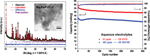
An iron-based pyrophosphate compound, Na2FeP2O7, is investigated as a positive electrode material for aqueous sodium-ion batteries for the first time. The high rate capability and good cyclability of this material in aqueous electrolytes are advantageous for low-cost and safe battery systems.


The increase of energy consumption and the demand for environmental energy resources have generated numerous investigations concerning several types of rechargeable batteries. In particular, research on rechargeable sodium-ion batteries (SIBs) has been promoted to utilize large energy storage systems (ESSs) as an alternative to lithium-ion batteries (LIBs) due to considerations of price and abundance in the world.1–3 While interest in SIBs has grown, concerns over safety using both Na metal as an anode and flammable organic solvents as electrolytes similar to the Li case have also arisen. Safety and a low price are the most important aspects of large-scale battery systems; hence, aqueous SIBs are attractive candidates to satisfy both these safety and cost requirements. In addition, aqueous solutions have further advantages of easy preparation, non-toxicity, and higher ionic conductivity than the currently employed organic solvents.

Despite these advantages of aqueous electrolytes, aqueous batteries have been troubled with the following drawbacks – a narrow potential window limited by the decomposition of water, the dissolution of electrode materials in aqueous solutions, and a short lifetime due to side reactions. Since Li et al. first introduced the feasibility of aqueous LIBs based on intercalation compounds,4 various types of electrode materials have been scrutinized for aqueous rechargeable batteries.5 Whereas most of the studies in aqueous systems have been focused on Li compounds, only a few sodium ion insertion materials in aqueous electrolytes have been studied compared with considerable investigations of sodium intercalative materials in nonaqueous electrolytes.6–13 Considering the requirements in aqueous batteries, the electrode materials for sodium aqueous systems are still limited. Therefore, the search for electrode materials that are inexpensive, easy to synthesize, stable, safe, non-toxic, long-lasting, and fit in the suitable potential in aqueous systems is necessary for the development of safe and inexpensive aqueous SIBs.

Recently, various pyrophosphate compounds have attracted attention as Na electrode materials due to their stable structure, good capacity retention, and high thermal stability.14–21 Among these compounds, sodium iron pyrophosphate (Na2FeP2O7) exhibits a reversible capacity of ∼80 mA h g−1 at approximately 3 V vs. Na+/Na, an appropriate potential range for neutral aqueous electrolytes. In particular, iron-based compounds have an advantage in terms of price, which is a considerable factor for the application of SIBs. Moreover, its 3D framework provides facile ionic conduction through its open channels, which are able to accommodate several sodium sites. Inspired by the impressive electrochemical characteristics of Na2FeP2O7 in organic electrolytes as well as the cost merit and robust crystal structure, we introduce here an iron-based sodium intercalative material, Na2FeP2O7, as a positive electrode for aqueous SIBs for the first time.

Na2FeP2O7 has been synthesized as a carbon composite form to overcome the intrinsic low electronic conductivity of the pyrophosphate compound. Fig. 1a presents the Rietveld refinement results with the synchrotron X-ray diffraction patterns of the as-synthesized Na2FeP2O7/C composite. The crystal structure of the composite was refined as a triclinic unit cell (P[1 with combining macron], no. 2), starting from the structure of the recently reported Na2FeP2O7.21 The refined lattice parameters are a = 6.3899(2) Å, b = 9.4562(2) Å, c = 11.020(1) Å, α = 63.738(1)°, β = 84.729(2)°, γ = 73.113(2)° and V = 570.88(3) Å3, respectively (Rwp = 7.28%, Rp = 5.63%, R(F2) = 5.48% and χ2 = 1.95). This crystal structure is the same as that of Na4−αM2+α/2(P2O7)2 (M = Fe, Mn, Ni),17,22 which is different from that of the first published Na2FeP2O7.14,16 However, the atomic ratio of Na, Fe and P was same to that of Na2FeP2O7 from detailed refined parameters, as demonstrated in Table S1. In parallel, the atomic ratio by ICP analysis was confirmed to be Na[thin space (1/6-em)]:[thin space (1/6-em)]Fe[thin space (1/6-em)]:[thin space (1/6-em)]P = 2[thin space (1/6-em)]:[thin space (1/6-em)]0.96[thin space (1/6-em)]:[thin space (1/6-em)]1.98. Therefore, we render this material as Na2FeP2O7, as already published elsewhere. The inset of Fig. 1a shows the crystal structure of the refined Na2FeP2O7 along the [1 0 0] direction. Sodium ions are accommodated at six sites; Na1, 2, and 3 with full occupancy and Na4, 5, and 6 with partial occupancy. The crystal structure consists of infinite arrays of [P2O7] and [FeO6] octahedra, which provide a 3-dimensonal framework for sodium ions to migrate efficiently.


image file: c3ra47560c-f1.tif
Fig. 1 (a) The synchrotron diffraction data with Rietveld refinement of Na2FeP2O7/C. The inset shows the crystal structure of the refined Na2FeP2O7 along the [1 0 0] direction. (b) An SEM image, (c) a TEM image and (d) an STEM image of the as-synthesized Na2FeP2O7/C. (e) An EDS mapping for C (purple), Na (red), Fe (blue) and P (green).

The morphology of the powders is depicted in Fig. 1b and c. The particles are agglomerated, and the diameter of the individual particles varies between 50 nm and 200 nm. The relatively small particle size may arise from the low synthetic temperature (600 °C) and from the carbon source (glycine) preventing particle growth. In addition, Fig. 1d and e also confirm the distribution of agglomerated powders based on the scanning transmission electron microscopy (STEM) and energy-dispersive spectroscopy (EDS) elemental mappings of the Na2FeP2O7/C composite. It can be clearly observed that carbon is homogeneously distributed all over the range of the particles, and Na, Fe and P are also uniformly detected inside the bulk of the particles (Fig. S1). Additionally, the carbon content of the composite is confirmed to approximately 15% using the element analyzer.

Fig. 2a presents two cyclic voltammograms of Na2FeP2O7/C in nonaqueous and aqueous electrolytes. The potential was converted into voltage vs. SHE (standard hydrogen electrode). A similar set of four redox peaks is present in both CV curves during oxidation and reduction; however, it is apparent that the intensities and shapes of the CV peaks in the aqueous electrolytes are more sharp and clear, and the polarization of each redox peak in the aqueous electrolytes is also reduced compared with that in the organic solvents, indicating faster kinetics in the aqueous electrolytes. In the aqueous electrolytes, five anodic current peaks at −0.21, 0.21, 0.33, 0.36 and 0.49 V vs. SHE (corresponding to 2.50, 2.92, 3.04, 3.07 and 3.20 V vs. Na+/Na) are observed during the oxidation process, which is consistent with previously reported results for Na2FeP2O7 in nonaqueous electrolytes regardless of the crystal structures.14,16 In addition, the single anodic peak at 0.42 V in the organic solvent electrolytes is slightly split into two peaks at 0.33 and 0.36 V in the aqueous solvents, in parallel to the data at the slower scan rate in the organic electrolytes,14 which also suggests rapid ionic diffusion in aqueous electrolytes. During the reduction process, there are four corresponding cathodic current peaks at −0.23, 0.18, 0.29 and 0.41 V vs. SHE. Similarly, the galvanostatic discharge profiles at 1 C and 5 C in nonaqueous and aqueous electrolytes are displayed in Fig. 2b. The profiles at the low C-rate (1 C) exhibit a similar distinctive voltage plateau in the two electrolytes; however, at the higher rate (5 C), the IR drop of Na2FeP2O7/C in the nonaqueous electrolytes is much larger than that in the aqueous electrolytes. Hence, the capacity at the high C-rate in the nonaqueous electrolyte is much lower (∼40 mA h g−1, half of the capacity at 5 C in the aqueous electrolytes) than that in the aqueous electrolytes. These trends are consistent with the previously reported results about electrode materials in organic solvents and aqueous solutions;11,23 it is generally accepted that the higher rate capability in aqueous electrolytes is attributed to the high ionic diffusivity of aqueous electrolytes. Additionally, Na2FeP2O7/C in aqueous systems exhibits excellent rate capabilities (Fig. S2). 40% of the initial capacity was still retained even when the C-rate is increased 250-fold from 0.2 to 50 C.


image file: c3ra47560c-f2.tif
Fig. 2 (a) CV curves of the Na2FeP2O7/C electrode in nonaqueous and aqueous electrolytes, (b) galvanostatic discharge curves of Na2FeP2O7/C at a rate of 1 C and 5 C in nonaqueous and aqueous electrolytes, (c) galvanostatic voltage-capacity profile at the C/5 rate in aqueous electrolytes, and (d) capacity retention at 1 C and 10 C-rate in aqueous electrolytes.

The electrochemical Na insertion/extraction process is believed to be consistent for both electrolytes in the same potential range based on the CV data and galvanostatic voltage profiles. Even though Na2FeP2O7/C shows the high reversibility and rate capability in aqueous electrolytes, one concern appears over the active voltage region that can be applied to the practical area because the reaction potential of the material covers the full range from −0.654 V to 0.576 V vs. SCE (Standard Calomel Electrode) in neutral aqueous solution. Thus, a suitable voltage region for a positive or a negative electrode for aqueous SIBs should be selected; the usable potential range from −0.2 V to 0.7 V vs. SCE (corresponding to 0.041 V to 0.941 V vs. SHE) is selected to further electrochemically test for Na2FeP2O7. This range suggests that two-thirds of full capacity can be utilized, similar to the case of Na0.44MnO2 as a positive electrode material for aqueous SIBs.6,23 Fig. 2c illustrates the galvanostatic voltage-capacity curve of the Na2FeP2O7/C electrode between −0.2 V and 0.7 V vs. SCE at a rate of 0.2 C (19.4 mA g−1). Despite the relatively low coulombic efficiency (∼93%) at 0.2 C, the battery delivers approximately 65 mA h g−1 of discharge capacity in a narrow voltage region. The initial coulombic efficiency increased at the 1 C and 10 C-rate in the same voltage range, and the value could be enhanced over 99.5% after 30 cycles, as illustrated in Fig. 2d. It is evident that Na2FeP2O7 in aqueous electrolytes exhibits decent capacity retention in spite of the narrow voltage range. The initial discharge capacity is 58 mA h g−1 between −0.2 and 0.7 V vs. SCE, and the capacity retention is approximately 86% after 300 cycles at the 1 C-rate. Even at the high rate of 10 C, the cell exhibits a comparable lifetime; the capacity retains approximately 37 mA h g−1 after 300 cycles of charge and discharge at the 10 C-rate. The detailed voltage-capacity profiles of the 1 C and 10 C cycles are displayed in Fig. S3. To compare the cyclability in nonaqueous electrolytes with the same voltage range, the cycling data and voltage profiles at 1 C cycles in nonaqueous electrolytes are presented in Fig. S4. Although Na2FeP2O7 is reported to have stable cyclability in nonaqueous electrolytes,14,17 the capacity retention in the narrow voltage region is gradually decreased due to the enforced voltage cut-off over the potential plateau at approximately 3 V vs. Na+/Na. Moreover, only half of the capacity (25 mA h g−1) could be produced in organic electrolytes at 1 C in the limited voltage range, further supporting the higher kinetics and stability of Na2FeP2O7 in aqueous electrolytes.

It can be inferred that the reversible electrochemical reaction of Na2FeP2O7/C in aqueous electrolytes does not originate from the side reaction of aqueous electrolytes but instead from the phase transition by the redox couple of Fe based on the analogous CV and galvanostatic voltage plateaus. The oxidation state of Fe would be more precisely understood by X-ray absorption near-edge structure (XANES) analysis; hence, ex situ XANES was conducted to investigate the redox behavior during electrochemical reaction in aqueous electrolytes, as shown in Fig. 3a. The XANES spectrum is clearly observed to shift to the right during the charging to 0.7 V vs. SCE (the green dot in Fig. 2c), indicating the oxidation of iron towards Fe3+. FeO and Fe2O3 were used as the Fe2+ and Fe3+ references, respectively. The XANES spectrum is also confirmed to shift back to lower valence states after the discharging process. The oxidation state of Fe at −0.2 V vs. SCE (the blue dot in Fig. 2c) is placed between Fe2+ and Fe3+, which is consistent with the galvanostatic results. To further confirm the change of the electrode after several cycles in aqueous electrolytes, an ex situ XRD pattern of the Na2FeP2O7/C electrode after 300 cycles in aqueous electrolytes was collected, as displayed in Fig. 3b. The XRD pattern of the 300-cycled electrode of Na2FeP2O7/C does not reveal any degradation or peak changes compared with the fresh electrode. The TEM image and EDS mappings of the cycled Na2FeP2O7/C also show no differences to compare with the fresh sample (Fig. S5).


image file: c3ra47560c-f3.tif
Fig. 3 (a) Fe K-edge XANES spectra of Na2FeP2O7/C after charge and discharge between 0.7 and −0.2 V vs. SCE in aqueous electrolytes and (b) ex situ XRD pattern of Na2FeP2O7/C after 300 cycles in aqueous electrolytes.

In summary, this report is the first to examine Na2FeP2O7 as a promising electrode material for low cost aqueous SIBs. The Na2FeP2O7/C composite enables reversible sodium ion de/insertion into its structure and also demonstrates a high rate capability, robust capacity retention and high stability in an aqueous environment. The remaining challenging point is the relatively low operating voltage of Na2FeP2O7; hence, a further study will be focused on enhancing the potential by modulating the redox couples of other transition metal elements or doping with an anion species.

Acknowledgements

This work was supported by the Program to Solve Climate Changes (NRF-2010-C1AAA001-2010-0029031) and Basic Science Research Program (2009-0094038) through the National Research Foundation of Korea (NRF) funded by the Ministry of Science, ICT & Future Planning. The authors thank the Pohang Accelerator Laboratory, Korea for extending the synchrotron XRD and XAFS beamline for characterization.

Notes and references

  1. M. D. Slater, D. Kim, E. Lee and C. S. Johnson, Adv. Funct. Mater., 2013, 23, 947 CrossRef CAS .
  2. H. L. Pan, Y. S. Hu and L. Q. Chen, Energy Environ. Sci., 2013, 6, 2338 CAS .
  3. V. Palomares, M. Casas-Cabanas, E. Castillo-Martinez, M. H. Han and T. Rojo, Energy Environ. Sci., 2013, 6, 2312 CAS .
  4. W. Li, J. R. Dahn and D. S. Wainwright, Science, 1994, 264, 1115 CAS .
  5. Y. Wang, J. Yi and Y. Xia, Adv. Energy Mater., 2012, 2, 830 CrossRef CAS .
  6. J. F. Whitacre, A. Tevar and S. Sharma, Electrochem. Commun., 2010, 12, 463 CrossRef CAS PubMed .
  7. A. D. Tevar and J. F. Whitacre, J. Electrochem. Soc., 2010, 157, A870 CrossRef CAS PubMed .
  8. C. D. Wessells, R. A. Huggins and Y. Cui, Nat. Commun., 2011, 2, 550 CrossRef PubMed .
  9. C. D. Wessells, S. V. Peddada, R. A. Huggins and Y. Cui, Nano Lett., 2011, 11, 5421 CrossRef CAS PubMed .
  10. J. F. Whitacre, T. Wiley, S. Shanbhag, Y. Wenzhuo, A. Mohamed, S. E. Chun, E. Weber, D. Blackwood, E. Lynch-Bell, J. Gulakowski, C. Smith and D. Humphreys, J. Power Sources, 2012, 213, 255 CrossRef CAS PubMed .
  11. S. I. Park, I. Gocheva, S. Okada and J.-i. Yamaki, J. Electrochem. Soc., 2011, 158, A1067 CrossRef CAS PubMed .
  12. Z. Li, D. Young, K. Xiang, W. C. Carter and Y. M. Chiang, Adv. Energy Mater., 2013, 3, 290 CrossRef CAS .
  13. X. Y. Wu, Y. L. Cao, X. P. Ai, J. F. Qian and H. X. Yang, Electrochem. Commun., 2013, 31, 145 CrossRef CAS PubMed .
  14. H. Kim, R. A. Shakoor, C. Park, S. Y. Lim, J. S. Kim, Y. N. Jo, W. Cho, K. Miyasaka, R. Kahraman, Y. Jung and J. W. Choi, Adv. Funct. Mater., 2013, 23, 1147 CrossRef CAS .
  15. T. Honma, T. Togashi, N. Ito and T. Komatsu, J. Ceram. Soc. Japan, 2012, 120, 344 CrossRef CAS .
  16. P. Barpanda, T. Ye, S. Nishimura, S. C. Chung, Y. Yamada, M. Okubo, H. S. Zhou and A. Yamada, Electrochem. Commun., 2012, 24, 116 CrossRef CAS PubMed .
  17. K. H. Ha, S. H. Woo, D. Mok, N. S. Choi, Y. Park, S. M. Oh, Y. Kim, J. Kim, J. Lee, L. F. Nazar and K. T. Lee, Adv. Energy Mater., 2013, 3, 770 CrossRef CAS .
  18. C. S. Park, H. Kim, R. A. Shakoor, E. Yang, S. Y. Lim, R. Kahraman, Y. Jung and J. W. Choi, J. Am. Chem. Soc., 2013, 135, 2787 CrossRef CAS PubMed .
  19. P. Barpanda, J. C. Lu, T. Ye, M. Kajiyama, S. C. Chung, N. Yabuuchi, S. Komaba and A. Yamada, RSC Adv., 2013, 3, 3857 RSC .
  20. P. Barpanda, T. Ye, M. Avdeev, S. C. Chung and A. Yamada, J. Mater. Chem. A, 2013, 1, 4194 CAS .
  21. P. Barpanda, G. Liu, C. D. Ling, M. Tamaru, M. Avdeev, S. Chung, Y. Yamada and A. Yamada, Chem. Mater., 2013, 25, 3480 CrossRef CAS .
  22. F. Erragh, A. Boukhari, F. Abraham and B. Elouadi, J. Solid State Chem., 2000, 152, 323 CrossRef CAS .
  23. D. J. Kim, R. Ponraj, A. G. Kannan, H. W. Lee, R. Fathi, R. Ruffo, C. M. Mari and D. K. Kim, J. Power Sources, 2013, 244, 758 CrossRef CAS PubMed .

Footnote

Electronic supplementary information (ESI) available. See DOI: 10.1039/c3ra47560c

This journal is © The Royal Society of Chemistry 2014
Click here to see how this site uses Cookies. View our privacy policy here.