Effect of electron irradiation on electroactive phase and dielectric properties of PVDF films
Hui-Jian
Ye
,
Li
Yang
,
Wen-Zhu
Shao
,
Yang
Li
,
Song-Bai
Sun
and
Liang
Zhen
*
School of Materials Science and Engineering, Harbin Institute of Technology, Harbin 150001, China. E-mail: lzhen@hit.edu.cn; Fax: +86-451-86413922; Tel: +86-451-86412133
First published on 23rd January 2014
Abstract
The effect of electron irradiation on the crystal structure and dielectric properties of poly(vinylidene fluoride) (PVDF) films was investigated. X-ray diffraction (XRD) and differential scanning calorimetry (DSC) were employed to examine the degree of participation in PVDF and the relative fraction of electroactive phase as well as the thermal property of PVDF films. The results showed that both the exothermal peak temperature and the crystallinity of the irradiated film decreased with increasing doses. Huge damage on the morphology of spherulite was observed in irradiated films by atomic force microscopy (AFM). The results of fine structures in PVDF films characterized by X-ray absorption near edge structure (XANES) implied that the dominance of the oxidation reaction occurred during irradiation, and further induced destruction of the regular packed structure. The results indicate that the β-phase exhibits good anti-irradiation ability during the electron irradiation on PVDF film. Because a large portion of the electroactive phase is maintained and intermediate phases are produced in the irradiated PVDF sample, the irradiated film exhibits a relatively high dielectric constant (around 7.8 under 2200 kGy) with low loss.
Introduction
Poly(vinylidene fluoride) (PVDF) exhibits huge substantial interest from electric storage to energy transformation because of its outstanding mechanical flexibility, high breakdown strength, low cost and also processing advantages.1–4 Meanwhile, dielectric capacitors with high energy density can significantly reduce the weight, the volume and the cost of the entire energy storage system. In general, the energy density is defined as electrostatic energy per unit volume or unit mass, which in a dielectric material is proportional to the product of the dielectric constant and the square of the applied electric field.5–7 PVDF has a very simple chemical formula with constitutional repeating unit –CH2–CF2–. This simple chemical structure guarantees both great mechanical flexibility and steric constraint of PVDF chains. Due to these structure characteristics, there are several different kinds of geometric configurations and crystal structures in PVDF, depending on the processing conditions of the fabrication process. Given the packing modes of these molecular chains into the unit cell, macromolecular conformations of PVDF appear in four kinds of crystalline phases known as α, β, γ, and δ. In view of practical applications, the α- and β-phases are the most important crystalline structures. The non-polar α-phase is trans-gauche (TGTG′) conformation, and exhibits low permittivity. This kind of PVDF sample can be normally obtained from a molten sample cooled to room temperature at a regular cooling rate or solvent cast at solvent evaporation temperature above 120 °C. The β-phase with all-trans bond (TTTT) conformation is comprised of fluorine atoms on one side and hydrogen atoms on the opposite side of the polymer backbone, which leads to the highest net dipole moment among these four different polymorphs.8 The unit cell of the β-phase contains two identical all-trans chains packed with oriented dipoles, which are perpendicular to the polymer main chain. Two principal requirements were suggested for a ferroelectric material: the net dipole moment of the crystal structure is non-zero and the dipoles should have identical orientation in the bulk sample.9 Therefore, PVDF provides wonderful ferroelectric properties, such as high piezoelectric constant and great dielectric performance, which are key parameters related to the applications of energy conversion and storage involving the electroactive properties of dielectric materials.It is reported that irradiation on the polymer will induce changes of the chemical structure and inherent properties of polymers, for example, crosslinking of chains, main chains scission and evolution of chemical as well as physical properties of the samples.10–13 The effect of irradiation on the gel of PVDF was studied, and the results showed that the gel increased quickly at the initial stage at doses below 1013 cm−2, which is ascribed to the crosslinking reaction during irradiation greatly affecting the crystal structure of the sample.14,15 Due to non-linear effects in the proton irradiation, the number of radicals produced is lower than that of electron irradiation. Dimensional adjustments of adaptive polymer films depend on charge deposition and require the detailed understanding responses of piezoelectric material which are expected to deteriorate owing to strong vacuum UV, energetic particles and atomic oxygen exposure in space.16–19 Giant electrostriction and electrocaloric effects have been found in irradiated poly(vinylidene fluoride-trifluoroethylene) (P(VDF-TrFE)) copolymer, which also displays relaxor ferroelectric behavior due to irradiation.20–22 This is attributed to the fact that the all-trans poling region was destroyed and then a nano-sized non-polar region was produced, the difference between those two regions would cause high responding strain under an external electric field in the ferroelectric polymer near the first-order ferroelectric–paraelectric (FE–PE) transition where multiple intermediate phases may exist.
Though the properties of irradiated PVDF have been studied in recent years, the anti-irradiation performance of different phases in the PVDF should be paid attention to since β-PVDF exhibits great ferroelectric properties. Also some important issues in the irradiated PVDF, especially on those related to β-phase contents, melting points and dielectric property need to be clarified due to current conflicting results. Meanwhile, the advanced technology of characterization on materials provides the possibility for further research on fine structure induced by irradiation. X-ray absorption near edge structure (XANES), which provides a new solution to explore the relationship of crystal structure and properties of polymers, was employed to analyze the detailed change of electron structure of fluorine and carbon elements in PVDF induced by the irradiation. In this study the effect of electron irradiation on the crystal structure and fine structure as well as inherent properties of PVDF was investigated. XRD was applied to characterize the degree of participation in PVDF and calculate the relative fraction of the β-phase. The morphology of bulk PVDF under various irradiation doses was examined by atomic force microscopy (AFM).
Experimental
Raw materials and film preparation
Poly(vinylidene fluoride) (PVDF) powders and N,N-dimethylacetamide (98+%, chemical pure) were purchased from Shanghai 3F Co. Ltd and Sinopharm Chemical Reagent Co. Ltd, respectively, and used without further purification.The PVDF films were obtained via simple solution casting method. The PVDF powder (0.5 g) was initially dissolved in dimethylacetamide (DMAc) (10 mL). After the mixture was stirred at 60 °C for 30 min and then ultrasonicated for 10 min and stewed for 20 min to make sure that extra gas bubbles were removed completely before pouring on the glass plate. Finally the mixture was dried at 80 °C for 90 min and then held at 130 °C for 8 h to remove the extra solvent and finally cooled slowly to room temperature. The thickness of the dried film in this study is around 60 μm.
Irradiation of PVDF films
The electron irradiation was performed at the DD 1.2 MV accelerator in the Technical Physics Institute of Heilongjiang Academy of Science. PVDF samples were cut into 2 × 2 cm2 and then fixed on a wire netting substrate to avoid movement during the irradiation and then irradiated at 1.12 MeV at doses from 500 to 2200 kGy. The deviation of the dose rate is less than 2% and uncertainty of electron energy is smaller than 5%.Characterization of irradiated PVDF films
In order to determine and characterize the influence of electron irradiation, the presence of the different crystalline phases in PVDF film was examined by X-ray diffraction (XRD), which was performed on a Rigaku Ultima IV diffractometer (Japan Riguka) using a Cu Kα radiation source with a rate of 4° per minute and 2θ angle ranging from 10° to 60°. Atomic force microscopy (AFM) (Bruker Dimension Icon, German) with a tapping mode was employed to observe the morphologies of PVDF films under various doses. The tip was TESPA type with frequency 414 Hz and the scanning scope was 80 × 80 μm2. Differential scanning calorimetry (DSC, TA Q2000) profiles were collected from room temperature to 180 °C, and the rate of heating and cooling was 10 °C min−1. Dry high-purity nitrogen gas was sent into DSC cell through the whole experiment with a flow rate of 50 mL per minute. The DSC sample, cut from the irradiated PVDF film, was sealed in aluminum pans and used for the entire experiment. Nearly all the samples had identical weight (about 5 mg) and thickness (around 60 μm). The thermal history of PVDF films were erased by heating at 180 °C for 3 min. The samples were then cooled to room temperature and heated to 180 °C at 10 °C min−1. The melting peak temperature and entropy were obtained from the thermograms by TA commercial software. The calibration of the DSC was made with the standard calibration of TA Q series. To explore the detailed changes of electron structure induced by irradiation, the fine structure of F and C elements in PVDF films were identified by X-ray absorption near edge structure (XANES). Soft X-ray absorption spectrum measurements of PVDF films were performed on the U18 beam line at Hefei National Synchrotron Radiation Laboratory, China. The energy range was 100–1000 eV, and the resolution at 1000 eV was 1000. The beam spot size on the sample was 3 mm horizontally, 1 mm vertically, and the scanning step was 0.2 eV. All the spectral measurements were taken by sample current mode at room temperature. Frequency-dependent dielectric constant and loss tangent (tan![[thin space (1/6-em)]](https://www.rsc.org/images/entities/char_2009.gif) δ) were measured at room temperature by an Agilent 4294A LCR meter from 100 Hz to 1.0 MHz at 0.5 Vrms. The thickness of the dried PVDF film was measured using a contact profilometer (Shenyang Kejing Ltd., China).
δ) were measured at room temperature by an Agilent 4294A LCR meter from 100 Hz to 1.0 MHz at 0.5 Vrms. The thickness of the dried PVDF film was measured using a contact profilometer (Shenyang Kejing Ltd., China).
Results and discussion
It is well-known that β-phase PVDF is comprised of fluorine and hydrogen atoms on the opposite sides with a great net dipole moment, and furthermore leads to high piezoelectric constant and dielectric property. Compared to these chains in the amorphous phase, sketch chains in crystalline regions are packed closely and mobility for any conformational changes is limited at ambient temperature.23 Consequently, the density of the β-phase crystal region is higher than other regions in bulk PVDF films. The different crystal structures of PVDF films with and without irradiation were established by XRD spectra. The XRD patterns for the different crystalline phases of PVDF are easy to distinguish because of a characteristic peak for each crystal structure. The diffraction angles of 2θ = 18.0° and 19.9° belong to (020) and (021) of α-phase, while 2θ = 20.7° and 20.8° are (110) and (200) of β-phase crystal structure.24 XRD patterns of PVDF films under various irradiation doses are displayed in Fig. 1. The differences of relative height of those two peaks after irradiation verify that the conversion of two phases occurred during the irradiation. The intensity of the peak assigned to β-phase decreases under increasing dose, correspondingly the intensity of α-phase peak increases in the same treating process, which indicates that the conversion of β to α-phase took place in the irradiation. Also there is a new peak at 27.08 belonging to α-phase that appeared after the irradiation. This also was verified by the results of PVDF irradiated with the non-uniform KrF excimer laser that the photochemical reaction took place between the laser and PVDF material and the laser broke the C–F bond, and furthermore polycrystalline and single crystal graphite was generated on the surface of PVDF.25 The intensity of the band representing β-phase decreased after laser irradiation. | ||
| Fig. 1 XRD patterns of PVDF films under various irradiation doses. | ||
The evolution of corresponding electroactive phase under different fluence is shown in Fig. 2. It can be observed that the electron irradiation will reduce the relative fraction of β-phase. Generally, the relative content of β-phase decreases with increasing doses. The content of β-phase of the as-prepared film is pretty high (41.8%), which gradually reduces after being exposed to the electron beam, and reaches 34.7% at a dose of 2200 kGy. As discussed above, high β-phase crystal fraction refers to the large amount of planar zigzag conformations with all of the fluorine atoms located on the same side of the polymer chains. During the irradiation process, scission reaction (free radical formation) took place and induced an increase in molecular mobility.26 Thus the relative fraction of β-phase decreases after being exposed to the increasing doses.
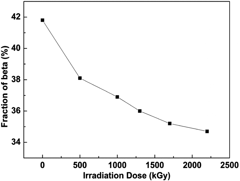 | ||
| Fig. 2 Evolution of the β-phase content for PVDF films under different doses. | ||
All the thermal property experiments were conducted on each sample in the aluminum pan of the DSC cell during the entire experiment. After the first melting, the repeatability is excellent. For instance, melting and cooling cycles of films at a dose of 1300 kGy go for five times and the difference in the endothermal peak position is smaller than 0.2% while the difference in the crystalline fraction which is determined by the integration of the peak is smaller than 1.3%. Repeatability of a series of different samples is examined with two sealed samples of the same dose and went for melting and crystallization cycles. Uncertainty of endothermic peak temperature is still less than 0.3% and the difference of crystallization fraction is less than 2.5%. This also indicates that the samples were irradiated uniformly.
Typical DSC thermograms of samples exposed to irradiation at various doses are displayed in Fig. 3. The exothermal peak shifts toward lower temperature as the irradiation dose increases. For example, the melting peak of original PVDF film is 163.4 °C, and then it falls down to 139.0 °C at a dose of 2200 kGy. There is a huge reduction of peak temperature for PVDF films under various electron beam doses. This phenomenon can be explained by the increase of molecular mobility caused by scission reaction during irradiation. The thermal stability of any polymer material is diagnostic of a radical species and largely determined by the strength of the covalent bond between the atoms forming the polymer.
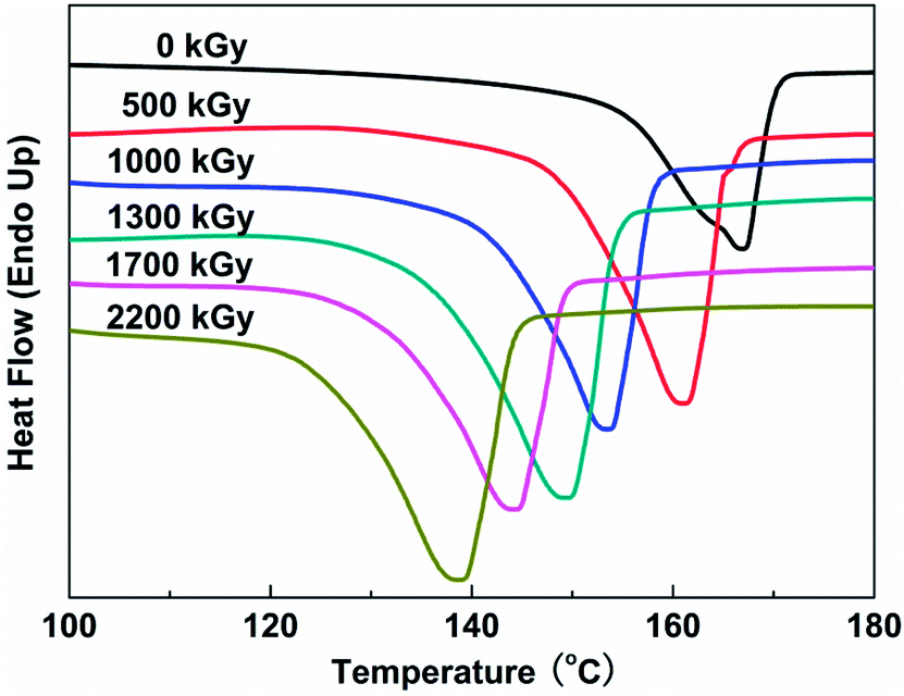 | ||
| Fig. 3 DSC profiles of PVDF films under various irradiation doses. The heating rate is 10 °C min−1. | ||
Irradiation will rearrange the packing of PVDF chains and induce the change of color of PVDF films. The irradiated film presents faint yellow at high doses instead of white as the result of fabrication. This indicates that the irradiation promoted certain changes in the properties of the samples.27 The melting enthalpy and peak temperature for PVDF films under different doses are listed in Table 1. The crystallization fraction is calculated from the integration of the endothermic peaks, assuming that the melting enthalpy of the 100% crystalline α-PVDF is 93.07 J g−1.28 The corresponding degree of crystallinity (Xc) is calculated by eqn (1):29
| Xc(%) = ΔHc/ΔHc0 × 100% | (1) |
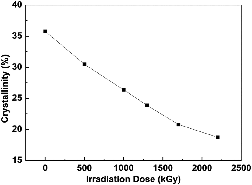 | ||
| Fig. 4 Evolution of the crystallinity of PVDF films under various irradiation doses. | ||
| Irradiation dose (kGy) | Melting enthalpy (J g−1) | Melting peak temperature (°C) |
|---|---|---|
| 0 | 38.4 | 163.4 |
| 500 | 32.7 | 161.3 |
| 1000 | 28.3 | 153.7 |
| 1300 | 25.6 | 149.6 |
| 1700 | 22.3 | 144.4 |
| 2200 | 20.1 | 139.0 |
The surface morphologies of PVDF films were examined by AFM in pizeo-response mode, and three dimensional images of 80 × 80 μm2 area of samples with various fluxes are obtained and depicted in Fig. 5. The bright and dark area corresponds to a peak and valley depth, respectively. The grain morphology of the original sample shown in Fig. 5a exhibits consistent microstructural features in PVDF crystal region and the surface roughness of crystal segments is about 2 μm. After applying different doses, the surface roughness is reduced sharply and decreases to 500 nm at a dose of 1300 kGy. Under the highest dose in this study, 2200 kGy, the surface morphology is corroded so abruptly that only a few grains are left in the irradiated sample. The compact spherulitic morphology in the unirradiated film is assigned to α-phase, while the meshlike structure that appeared in the irradiated films is the characteristic of β-crystalline phase, which indicates that the electroactive phase exhibits good anti-irradiation performance.31 As discussed above, the crystallinity of PVDF decreases after being exposed to the electron beam, indicating that a large part of the crystal region was destroyed. It can be observed that before irradiation the diameter of spherulite is between 15 and 20 μm and the surface is very smooth. However, electron irradiation causes a rough surface in the grain crystal and the damage is aggravated with increasing fluence. Finally at high doses the morphology of spherulite almost was ruined. The irradiation of PVDF films in atmospheric air leads mainly to partial degradation through the formation of acid fluoride groups O![[double bond, length as m-dash]](https://www.rsc.org/images/entities/char_e001.gif) C–F, particularly expected in the near-surface regions.32 It also allows for an assessment of crystalline morphological features and quantification of the polar β-phase.16 The result of morphology is consistent with the sharp reduction of crystallinity of PVDF after irradiation. A marked increase in the relief of the parallel strips was observed after irradiation. This phenomenon was especially significant with the increasing dose of electron and resulted from the shape of the PVDF spherulite produced by injection of electrons.
C–F, particularly expected in the near-surface regions.32 It also allows for an assessment of crystalline morphological features and quantification of the polar β-phase.16 The result of morphology is consistent with the sharp reduction of crystallinity of PVDF after irradiation. A marked increase in the relief of the parallel strips was observed after irradiation. This phenomenon was especially significant with the increasing dose of electron and resulted from the shape of the PVDF spherulite produced by injection of electrons.
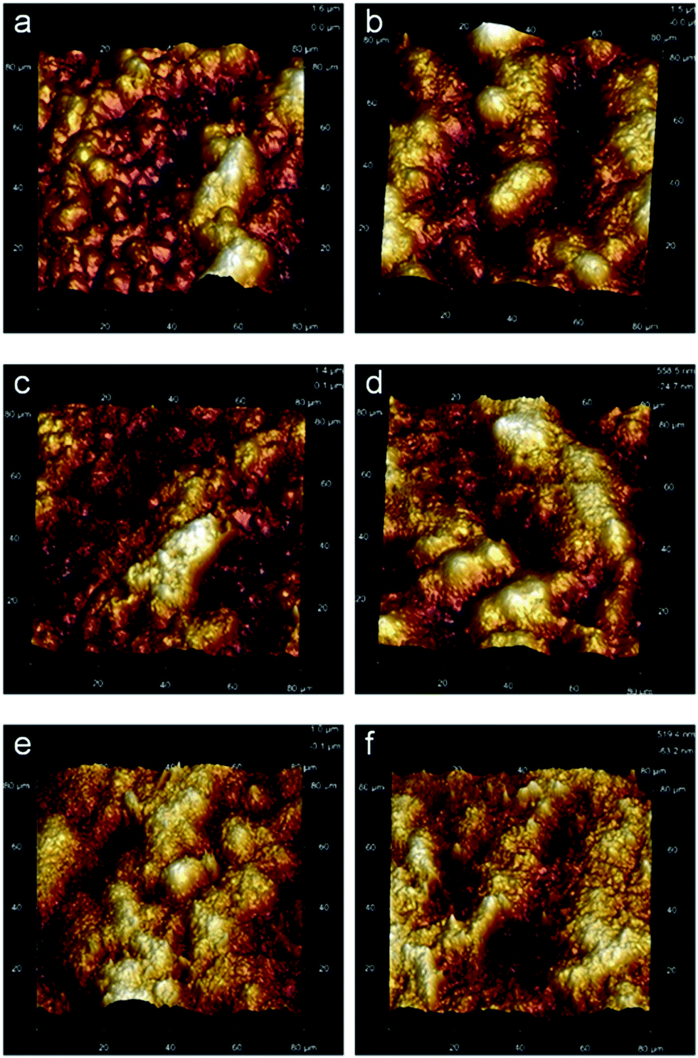 | ||
| Fig. 5 Three dimensional images by AFM of PVDF films under various doses: (a) 0 kGy, (b) 500 kGy, (c) 1000 kGy, (d) 1300 kGy, (e) 1700 kGy and (f) 2200 kGy. | ||
Details of the molecular structure have a key relation with the features that control crosslinking sites, irradiation degradation reactions, and morphological properties related to crystallinity. To analyze the electron structure of PVDF films induced by electron beam, the fine structure of C and F elements in PVDF were identified by XANES with synchrotron radiation light in Hefei National Synchrotron Radiation Laboratory, China. Fig. 6 shows the X-ray absorption spectra of C and F atoms. All the spectra were normalized. The intensity of the spectrum corresponds to the transition probability of electrons at the core excited state from inner shell into unoccupied.33 There are huge differences in the C element after irradiation. Compared with the untreated PVDF sample, the absorptions of carbon atoms at 284.8 and 288.2 eV are assigned to π* excitations, as well as other peaks, such as 287.2, 287.9, 288.8, 292.2 and 294.4 eV, which are assigned to σ* excitations. The stronger peak at 287.9 eV and the comparatively weaker one around 287.2 eV can be assigned to the transition from C1s to σ*C–H in –CH3 groups in accordance with previous assignments in literature for similar species. Also the absorption at 288.8 eV belongs to the transition from C1s to σ*C–H in –CH2CH2– groups. A new strong peak at 288.2 eV assigning to CO π* transition appears in the irradiated PVDF film. Among all peaks, the absorption at 292.3 eV exhibits the hugest increase of intensity corresponding to C–C and/or C–O bonds due to the increase of C–O moieties in the sample after irradiation, which indicates that the density of C–O increases because of degradation of the carbon chain with oxygen. The pattern of C 1s (C–H) to 1π* CC transition at the peak of 284.8 eV is the key to distinguishing polymer sample after irradiation. Quantitative comparison, there is an almost 20% increase in the transition to π* CC peak intensity. According to the previous work, the activity of hydrogen couplings in alkyl radicals ranges from near zero to high value, depending on the orientation of the C–H bond with respect to the unpaired electron orbital.34 The former chemical structure of chain skeleton changes from C–C to CC bond caused by dehydrofluorination, elimination of HF, and the subsequent crosslinking, whereas the latter is assigned to CO (carbonyl) resulting from the formation of hydroperoxide radicals initiated by irradiation in environment with oxygen gas. The small peak at 288.8 eV, which disappeared after irradiation, was assigned to the transition from C1s(C–R) to π* (CC) and/or σ* (C–H). The dominance of degradation of the samples that occurred under increasing dose based on energy transfer via exciton migration is reported to be a prominent mechanism in the production of small molecules.26 Due to the higher bond strength of C–C bonds, C–H bonds are broken more frequently under irradiation than C–C bonds. C–C bond cleavages are further healed by recombination of the chain ends, since the two macromolecular fragments which arise only very slowly diffuse out from the area where fragments were produced. The degradation is considered as the dominant initial chemical reaction.18
| –CF2–CH2–CF2–CH2– → –CF2–CH2–CF2–CH˙– + H˙ | (2) |
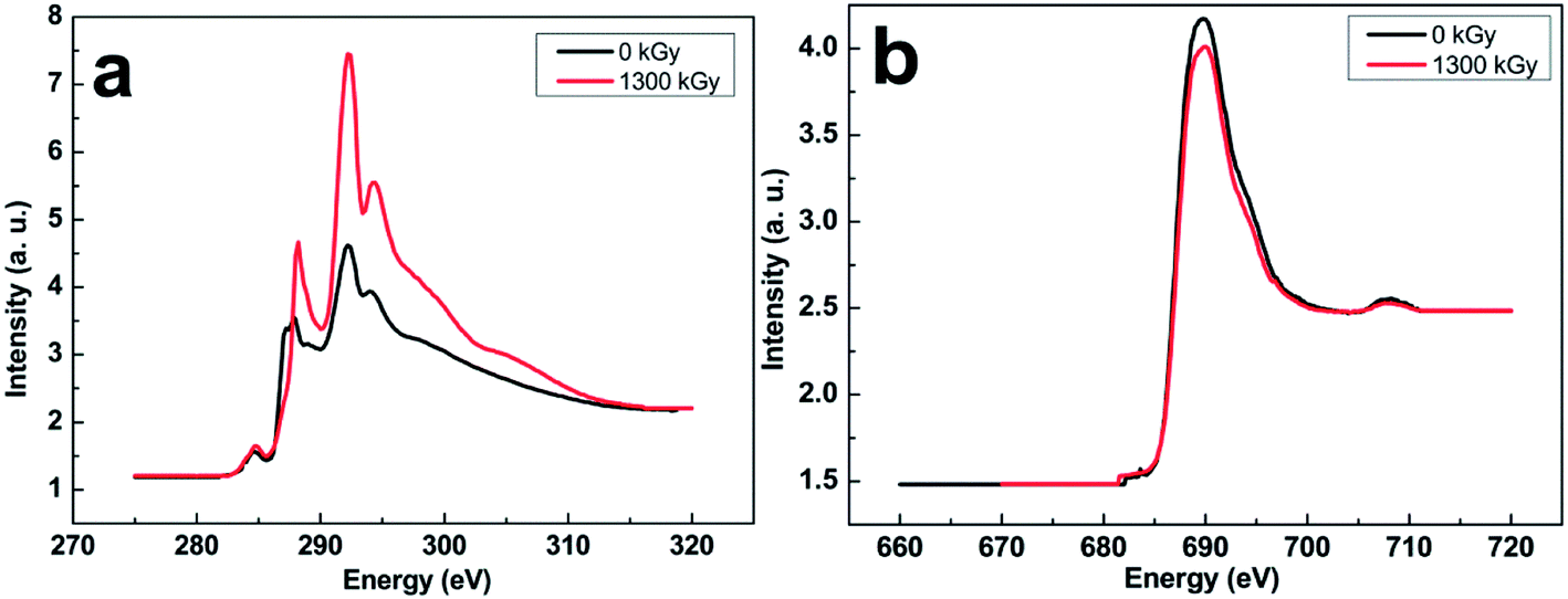 | ||
| Fig. 6 Normalized XANES spectra of (a) C and (b) F elements from original and irradiated PVDF films with the dose of 1300 kGy. | ||
The hydrogen atom generated in this process will abstract a fluorine atom from a neighboring molecule:
| –CF2–CH2–CF2–CH˙– + H˙→ HF + –CF2–CH2–CFCH– | (3) |
It's been verified that the groups of CF2, CF, CH2, CH, and –CC– species coexist in the irradiated PVDF sample, while CF groups can be produced as two distinct states. The decomposition of HF as described is expected to undergo simultaneously due to carbonization, which is dependent on the presence of adjacent CH2 and CF2 and distinctions between polymer chains.13
The near edge of F element in PVDF shown in Fig. 6b also has a difference after the irradiation, in which the K edge absorption peak at 690.0 eV decreases. This reduction at 690.0 eV indicates that the density of unoccupied electrons state of F atom decreases induced by irradiation. Due to partial degradation and crosslinking induced by electron beam, the structure of identical all-trans chains packed with oriented dipoles of F atoms was destroyed. Then the crystal region and β-phase content reduced in the bulk films, and F atom may produce coordination with hydrogen and other fluorine atoms.35 Meanwhile, head-head-tail-tail chain defect configuration which is the most frequent defect structure appeared. Chain defect is a common occurrence in free radical polymerization reactions used to manufacture vinylidene fluoride-based polymers.16 Thus the density of unoccupied state of electrons decreased after the orientation. The mechanism should be implemented with the radiation induced crosslinking reactions taking place in the matrix as well as with other reactions (addition of H atoms) taking place at the crystal and amorphous interface and leading to grafted crosslinking chains. XANES is new technology to examine detailed changes of electron structure in polymers, especially on ferroelectric polymers, thus a lot of work has to be done to analyze the change of electron structure accurately.
Owing to the decrease of β-phase after exposure to the increasing doses, the dielectric performance of PVDF films is also affected. The dielectric spectroscopy measured at room temperature on PVDF films over the frequency range 100 Hz to 1 MHz is shown in Fig. 7. As discussed above, the β-phase crystal structure of PVDF reduces after irradiation of the host polymer, which results in a decrease of the dielectric constant of irradiated PVDF film. The dielectric constant of PVDF ferroelectric polymer used in this study is about 11.2 at 100 Hz, which is much higher than other kinds of ferroelectric polymers.36 After the samples were irradiated the dielectric constant of PVDF film decreases by 30% and reaches 7.8 at a dose of 2200 kGy at 100 Hz (Fig. 7a). The dielectric constant of irradiated film is independent to the frequency and decreases little at the starting frequency, though it will decrease under high frequency, which provides a broad application requesting high dielectric constant below 105 Hz. It is believed that the dielectric constant of the polymer is primarily influenced by the polarity and activity of dipoles in the macromolecule,37,38 which is accompanied by the mobility of macromolecular chain segments, so the dielectric constant of PVDF film is affected by the beam dose. The depression of the dielectric constant indicates that electron irradiation will hinder the movement of macromolecular chain segments. With a large β-phase crystal fraction, which refers to the amount of planar zigzag conformations with all of the fluorine atoms located on the same side of the polymer chains, high chain packing and dipole density may be obtained.23 Large portions of the dipoles are able to be oriented in the same place without canceling each other under the action of an electric field.39 Accordingly, the β-phase crystal falls down with increasing doses because of the depression of the dipole moment and polarity of PVDF matrix. Due to large fraction of electroactive phase maintaining even under high dose of irradiation, PVDF film exhibits a high dielectric constant.
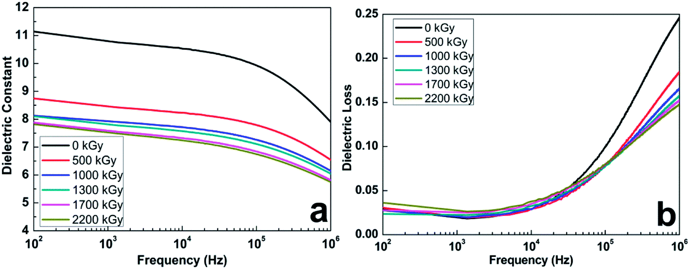 | ||
| Fig. 7 (a) Dielectric constant and (b) loss tangent of PVDF films from 100 Hz to 1 MHz at room temperature under different doses. | ||
The loss in dielectric materials is often expressed as loss tangent, also called as the dissipation factor, which is the ratio of the imaginary part of permittivity to real part of permittivity. The loss tangent of PVDF films with different doses from 100 Hz to 1 MHz at room temperature are shown in Fig. 7b. The values of dielectric loss are small at low frequency of PVDF films then increase at high frequency. The dielectric loss of PVDF with and without irradiation is pretty low, which is about 0.029 at 102 Hz of the original sample, compared with the range from 0.024 to 0.036 at the same frequency for irradiated samples. In the low dose, the loss values of samples remain steady. This indicates that permanently locking poled regions into the molecular chain structure reduce mobility after irradiation-induced crosslinking.15 Exposing to a high electron beam dose, the dielectric loss of the sample increases because of low packing density and polarity induced by irradiation leading to high mobility of polymer chains and dissipated energy. Concomitant crosslinking and scission reaction of PVDF chains during the irradiation, which hinders the diffusion of radicals for bimolecular coupling, leads to the decrease of dielectric loss in the high frequency.40
It is verified that the PVDF film prepared by the common method is comprised of trans-gauches (TG) and all-trans (TT) with some degree of correlations. A high degree of disorder in the ferroelectric phase of irradiated PVDF because of degradation of the polymer chain appears in the matrix, and induces a large entropy change in the sample near the first-order FE–PE transition.20 The decrease of regular dense structure after irradiation causes the decrease of dielectric constant and the increase of loss at low frequency. Compared with these chains in the amorphous phase, PVDF chains in crystalline regions are packed closely and the ability for any conformational changes is limited at ambient temperature. Because of the all-trans zigzag conformation, the density of β-phase crystal region is higher than other regions. Although the crystallinity of PVDF film decreases a lot after irradiation, the relative fraction of β-phase reduces a little, and the content of electroactive phase is about 35% even after high dose irradiation. It indicates that β-phase exhibits better anti-irradiation ability than α-phase. Because a large portion of the electroactive phase is left and many intermediate phases are produced in the irradiated PVDF samples,22,41 the dielectric constant of irradiated film is relatively high and exhibits independence of frequency, around 7.8 under 2200 kGy at 102 Hz, which is much higher than other kinds of ferroelectric polymers.36 Also the loss is about 0.03, which is still very low. Furthermore, the dielectric loss reduces significantly under high frequency after irradiation.
Conclusions
In summary, the effect of electron irradiation on the crystal structure and dielectric property of PVDF has been studied. The results show the reduction trend for the relative content of β-phase and the crystallinity as well as the maximum exothermal temperature of PVDF films with increasing doses. The spherulitic structure of α-phase was destroyed under the electron beam and β-phase exhibits good anti-irradiation performance. A large portion of CO π* and C–O σ* transitions appearing in the irradiated film indicates that the oxidation reaction occurred mainly during the irradiation. The irradiated PVDF film exhibits a relatively high dielectric constant and low loss because of a large fraction of remnant electroactive phase left after irradiation.
Acknowledgements
This work was supported by the National Natural Science Foundation of China (no. 11079018). The authors thank Dr R. C. Tian at Technical Physics Institute of Heilongjiang Academy of Science for irradiation of PVDF films and also thank Mr W. S. Yan at Hefei National Synchrotron Radiation Laboratory for XANES characterization. Hui-Jian Ye acknowledges Dr Cheng-Yan Xu for his comments and English correction and proofreading.Notes and references
- B. J. Chu, X. Zhou, K. L. Ren, B. Neese, M. R. Lin, Q. Wang, F. Bauer and Q. M. Zhang, Science, 2006, 313, 334–336 CrossRef PubMed.
- V. S. D. Voet, D. H. Merino, G. Brinke and K. Loos, RSC Adv., 2013, 3, 7938–7946 RSC.
- S. Wu, M. R. Lin, S. G. Lu, L. Zhu and Q. M. Zhang, Appl. Phys. Lett., 2011, 99, 132901 CrossRef PubMed.
- Z. C. Zhang, Q. J. Meng and T. C. M. Chung, Polymer, 2009, 50, 707–715 CrossRef PubMed.
- Q. Wang and L. Zhu, J. Polym. Sci., Part B: Polym. Phys., 2011, 49, 1421–1429 CrossRef.
- H. J. Ye, L. Yang, W. Z. Shao, S. B. Sun and L. Zhen, RSC Adv., 2013, 3, 23730–23736 RSC.
- W. J. Liao, A. J. Gu, G. Z. Liang and L. Yuan, Colloids Surf., A, 2012, 396, 74–82 CrossRef PubMed.
- A. Lovinger, Science, 1983, 220, 1115–1121 Search PubMed.
- R. Gregorio Jr and D. S. Borges, Polymer, 2008, 49, 4009–4016 CrossRef PubMed.
- A. Charlsby, Atomic radiation polymers, Pergamon Press, Oxford, 1960 Search PubMed.
- H. A. C. Gil, R. M. Fariab and Y. Kawano, Polym. Degrad. Stab., 1998, 61, 265–273 CrossRef.
- V. K. Tiwari, P. K. Kulriya, D. K. Avasthi and P. Maiti, J. Phys. Chem. B, 2009, 113, 11632–11641 CrossRef PubMed.
- A. Kuvshinov, L. Pesin, S. Chebotaryov, M. Kuznetsov, S. Evsyukov, T. Sapozhnikova and A. Mirzoev, Polym. Degrad. Stab., 2008, 93, 1952–1955 CrossRef PubMed.
- E. Cohen and A. Ophir, J. Appl. Polym. Sci., 2012, 126, 442–451 CrossRef.
- E. Adem, G. Burillo, R. J. Muñoz, L. Cota and M. Avalos-Borja, Polym. Degrad. Stab., 2003, 81, 75–79 CrossRef.
- M. Celina, T. R. Dargaville, R. A. Assink and J. W. Martin, High Perform. Polym., 2005, 17, 575–592 CrossRef PubMed.
- T. R. Dargaville, M. Celina and P. M. Chaplya, J. Polym. Sci., Part B: Polym. Phys., 2005, 43, 2503–2513 CrossRef.
- A. Chapiro, Nucl. Instrum. Methods Phys. Res., Sect. B, 1988, 32, 111–114 CrossRef.
- M. M. Nesef and K. Z. M. Dahlam, Nucl. Instrum. Methods Phys. Res., Sect. B, 2003, 201, 604–614 CrossRef.
- X. Li, S. G. Lu, X. Z. Chen, H. Gu, X. S. Qian and Q. M. Zhang, J. Mater. Chem. C, 2013, 1, 23–37 RSC.
- Q. M. Zhang, V. Bharti and X. Zhao, Science, 1998, 280, 2101–2104 CrossRef.
- X. Li, X. S. Qian, H. Gu, X. Z. Chen, S. G. Lu, M. Lin, F. Bateman and Q. M. Zhang, Appl. Phys. Lett., 2012, 101, 132903 CrossRef PubMed.
- B. J. Jungnickel, Poly(vinylidene fluoride) (overview), in Polymeric material handbook, ed. J. C. Salamone, CRC Press, New York, 1999. p. 7115 Search PubMed.
- M. E. Daniel and L. J. Brian, J. Polym. Sci., Part B: Polym. Phys., 2004, 42, 91–97 CrossRef.
- Y. Ji, J. Liu, Y. Jiang and Y. Liu, Spectrochim. Acta, Part A, 2008, 70, 297–300 CrossRef PubMed.
- Z. Zhao, J. Chu and X. Chen, Radiat. Phys. Chem., 1994, 43, 523–526 CrossRef.
- M. M. Nesef, H. Saidi and K. Z. M. Dahlam, Polym. Degrad. Stab., 2002, 75, 85–92 CrossRef.
- H. S. Nalwa, Ferroelectric Polymers: Physics, Chemistry and Applications, M. Dekker, Inc., London, 1995, vol. 1, pp. 65–96 Search PubMed.
- L. L. Sun, B. Li, Z. G. Zhang and W. H. Zhong, Eur. Polym. J., 2010, 46, 2112–2119 CrossRef CAS PubMed.
- J. S. Forsythe and D. J. T. Hill, Prog. Polym. Sci., 2000, 25, 101–136 CrossRef CAS.
- K. V. Tiwari, K. D. Avasthi and P. Maiti, ACS Appl. Mater. Interfaces, 2011, 3, 1398 Search PubMed.
- M. M. Senna, H. A. Aly, Z. I. Ali and A. M. El-Naggar, Polym. Degrad. Stab., 2001, 71, 53–60 CrossRef CAS.
- S. S. Dhesi, G. van der Laan, E. Dudzik and A. B. Shick, Phys. Rev. Lett., 2001, 87, 067201 CrossRef CAS.
- T. Okajima, K. Hara, M. Yamamoto and K. Seki, Polymer, 2012, 53, 2956–2963 CrossRef CAS PubMed.
- C. K. Satyanarayana and K. Bolton, Polymer, 2012, 53, 2927–2934 CrossRef PubMed.
- Y. Wang, X. Zhou, Q. Chen, B. J. Chu and Q. M. Zhang, IEEE Trans. Dielectr. Electr. Insul., 2010, 17, 1036–1042 CrossRef CAS.
- J. Fan, X. Hu and C. Y. Yue, J. Polym. Sci., Part B: Polym. Phys., 2003, 41, 1123–1142 CrossRef CAS.
- W. J. Liao, A. J. Gu, G. Z. Liang and L. Yuan, Colloids Surf., A, 2012, 396, 74–82 CrossRef CAS PubMed.
- R. Gregorio and E. M. Ueno, J. Mater. Sci., 1999, 34, 4489–4500 CrossRef CAS.
- D. Dondi, A. Buttafava, A. Zeffiro, L. Conzatti and A. Faucitano, Polymer, 2012, 53, 4579–4584 CrossRef CAS PubMed.
- Z. Kutnjak, J. Petzelt and R. Blinc, Nature, 2006, 441, 956–959 CrossRef CAS PubMed.
| This journal is © The Royal Society of Chemistry 2014 |