Novel self-assembled 2D networks based on zinc metal ion co-ordination: synthesis and comparative study with 3D networks†
Deepa Rajwara,
Xinfeng Liub,
Zheng Bang Lima,
Sung Ju Choa,
Shi Chenb,
Jens M. H. Thomasc,
Abbie Trewind,
Yeng Ming Lama,
Tze Chien Sum*b and
Andrew C. Grimsdale*a
aSchool of Materials Science and Engineering, Nanyang Technological University, Singapore. E-mail: ACGrimsdale@ntu.edu.sg; Fax: +65-6790 9081; Tel: +65-6790 6728
bDivision of Physics and Applied Physics, School of Physical and Mathematical Sciences, Nanyang Technological University, Singapore. E-mail: tzechien@ntu.edu.sg; Fax: +65-6316 2971; Tel: +65-6795 7981
cInstitute of Integrative Biology, University of Liverpool, Liverpool, L69 7ZB, UK
dDepartment of Chemistry, Lancaster University, Bailrigg, Lancaster, LA1 4YB, UK
First published on 2nd April 2014
Abstract
The synthesis of linear and trigonal terpyridine bearing molecules (tpys) and their self-assembly to form novel extended self-assembled 2D networks of trigonal tpys with linear tpys through zinc metal ion (Zn2+) co-ordination is reported. The resulting Zn2+ co-ordination networks have been characterized by means of X-ray photoelectron spectroscopy (XPS), small angle X-ray scattering (SAXS), BET, and photophysical methods. The presence of some short range order in these networks has been shown by the SAXS results and these results have been analyzed with the help of molecular modelling studies. These metallo-supramolecular Zn2+ networks revealed the influence of the metal ion on the thermal and optical properties of the synthesized metallo-supramolecular assemblies, similar to the results previously reported for 1D and 3D self-assembled metallo-supramolecular materials. Moreover, these networks have shown high luminescence with a long fluorescence lifetime and good thermal stabilities. The monolayer of such ordered networks can be used as a template to build hierarchical nanostructures. These hierarchical nanostructures could be used as active components in electronic devices and as templates for the formation of hybrid organic–inorganic nanomaterials.
Introduction
Ordered 1D, 2D and 3D structures formed through self-assembly of organic molecules by non-covalent processes such as metal–ligand co-ordination offer considerable prospects for advances in nanoscience and progress in nanotechnology. The field of supramolecular electronics has progressed rapidly in recent years.1–4 Supramolecular electronics is one of the most promising “bottom-up” techniques in nanoelectronics of π-conjugated molecules with a device length of 5–100 nm. Supramolecular π-conjugated ‘oligomers’ have attracted much attention in last few decades due to the reversibility of the non-covalent interactions (hydrogen bonds, co-ordination bonds, hydrophobic interactions, electrostatic, and van der Waals interactions). Self-assembly rapidly and easily generates large and complex “supramolecules” (ensembles of individual molecules) from easily available building blocks with maximum efficiency. Synthesis of supramolecular networks from these building blocks becomes straightforward due to the thermodynamically driven self-correcting ability of non-covalent interactions. Metallo-supramolecular networks have attracted a lot of interest, not only because of the higher strength of this non-covalent interaction in comparison to other non-covalent interactions (such as hydrogen-bonding) but also for the self-healing ability and reversibility of these networks due to their dynamic nature. Co-ordination driven self-assembly, gives a better control over the rational design of supramolecular networks by taking advantage of the predictable nature of the metal–ligand co-ordination and ability of ligands to program directionality.5,6Thus, this strategy of metal–ligand co-ordination represents an alternative method for “bottom-up” technique in nanoelectronics by synthetic approach for designing molecules of required dimensions of few nanometers. For instance, a wide range of 1D, 2D and 3D systems formed by co-ordination bonding have been widely explored in past years.7–12 Hence, these supramolecular co-ordination networks have found a lot of prospective to be utilized for different nanotechnological applications. For example, supramolecular co-ordination networks formed by Fe metal ion co-ordination have been reported with excellent magnetic properties.10 Ru2+ co-ordination complexes with terpyridine ligands have been used in the building of polymer wires on gold.13 Zinc metal ion complexes are very well known for their optoelectronic properties14–18 and are potential candidates for many optoelectronic devices. In another application, non-linear optical properties of zinc metal ion co-ordination networks have been reported recently.19
Terpyridines were proposed as building blocks for supramolecular chemistry decades ago.20,21 Still there remains much scope for development in the supramolecular chemistry of terpyridines and much research work has been performed in this field.11,13,18,22–27 Transition metal-complexes of π-conjugated bis- and tris(terpyridine) have high prospective to be used as new functional materials in electronic and optoelectronic devices. Heavy transition metal ions, such as Pt2+, Ru2+, Os2+, and Ir2+ have been explored thoroughly in the past.20,24,28 In particular, electron-poor square-planar divalent Pt2+ and Pd2+ ions have been widely used in conjunction with electron-rich nitrogen containing moieties in the self-assembly process.25,29 Metal ions with filled electron shells have recently achieved much importance as models for the advancement of new metallopolymers. The low cost and nontoxicity of Zn2+ ions has made them a promising candidate for making highly developed co-ordination networks. The other advantage of using Zn2+ ions for co-ordination is that metal to ligand charge transfer (MLCT) processes do not occur in such systems, because of the full d10 electron configuration of the Zn2+ ions. Hence there is only the possibility of intraligand (IL) charge transfer in these systems. High PL quantum yields and EL performance have been reported30 using such systems. Winter et al. have used Zn2+ as a template to assemble organic building block into polymer chains through coordination to chelating terpyridyl units.18 These linear oligomers with tpy (2,2′:6′,2′′-terpyridine) end-groups self-assembled with Zn2+ to give luminescent polymers. Moving one step forward towards achieving ordered and extended networks, this paper mainly focuses on the synthesis of 2D metallo-supramolecular networks of Zn2+ ions with terpyridine ligands and a comparison of their optoelectronic properties with the 3D networks previously reported by us.12,19 To create metallo-supramolecular networks, monomers with self-assembling end-groups are mandatory. In the previous work in this field, the focus has been on linear and tetrahedral Zn2+ terpyridine networks. By systematic examination on their photophysical properties together with their structural characterization, it has been concluded that by changing conjugated backbone on the terpyridine units it is possible to modify the optoelectronic properties of these networks. Strong emission in the solid state indicates that these materials correspond to the capable candidates with respect to their potential applications in optoelectronic devices such as OLEDs. Hence it was anticipated that the Zn2+ based materials might be made solution processable by the attachment of more solubilizing groups to π-conjugated terpyridines. These complexes could be very promising candidate for solar cell applications. In extension of this work, the present investigations aim the design of zinc metal co-ordinated 2D networks made up of trigonal and linear π-conjugated terpyridines with respect to their possibility in the field of optoelectronic device applications. Various bis(terpyridine) derivatives were used in the synthesis of self-assembled supramolecular 2D networks by Zn2+ metal co-ordination with tpy ligands. Photophysical properties with respect to their device applications along with their thermal, and electrochemical properties, as well as ordering in their self-assembled networks, are discussed, with comparisons made to the similar 3D networks previously made by us.12,19 The chemical structures of basic building blocks for 2D self-assembled networks are shown in Fig. 1.
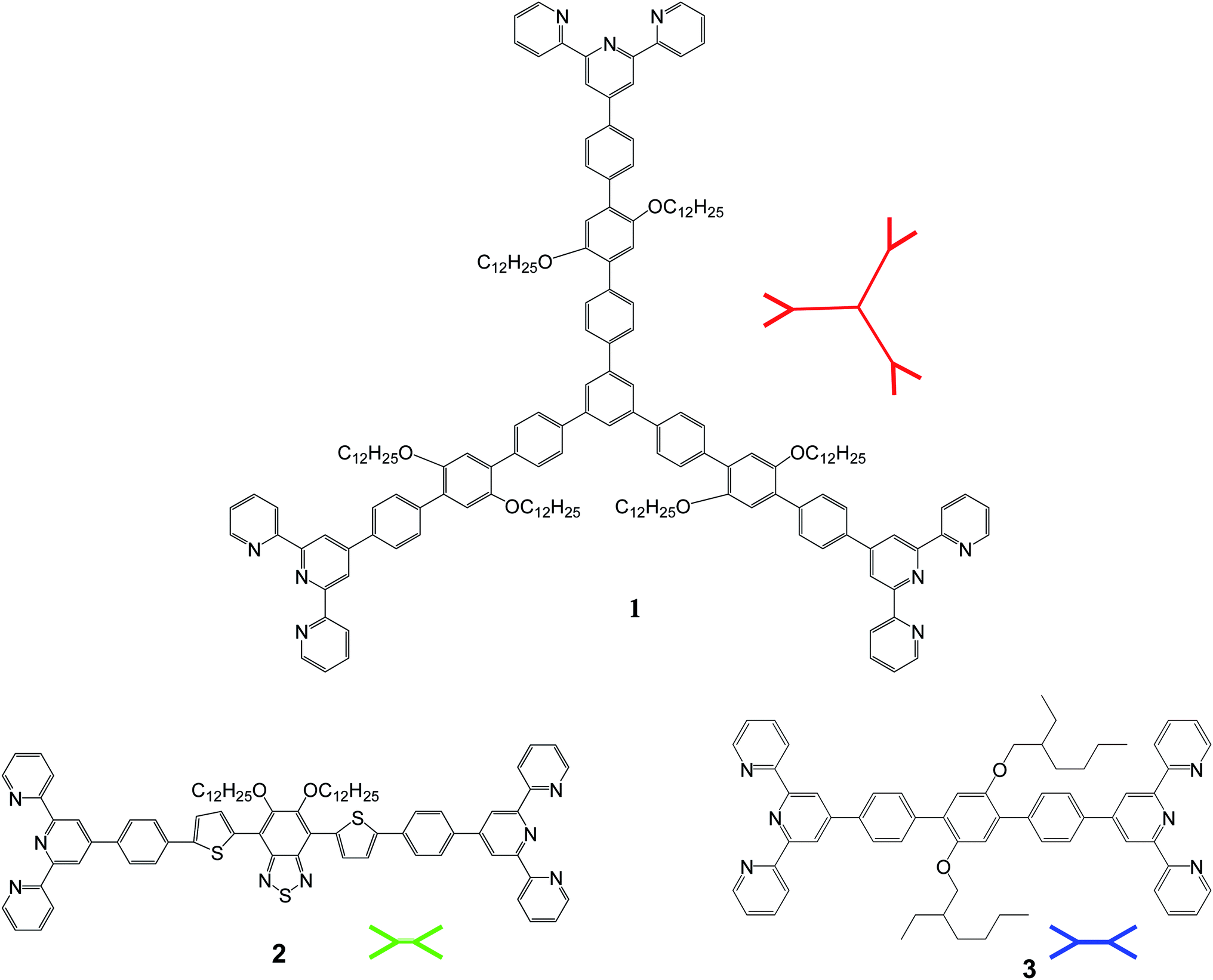 | ||
| Fig. 1 Molecular structure of basic building blocks for 2D self-assembled networks. | ||
Results and discussion
Synthesis
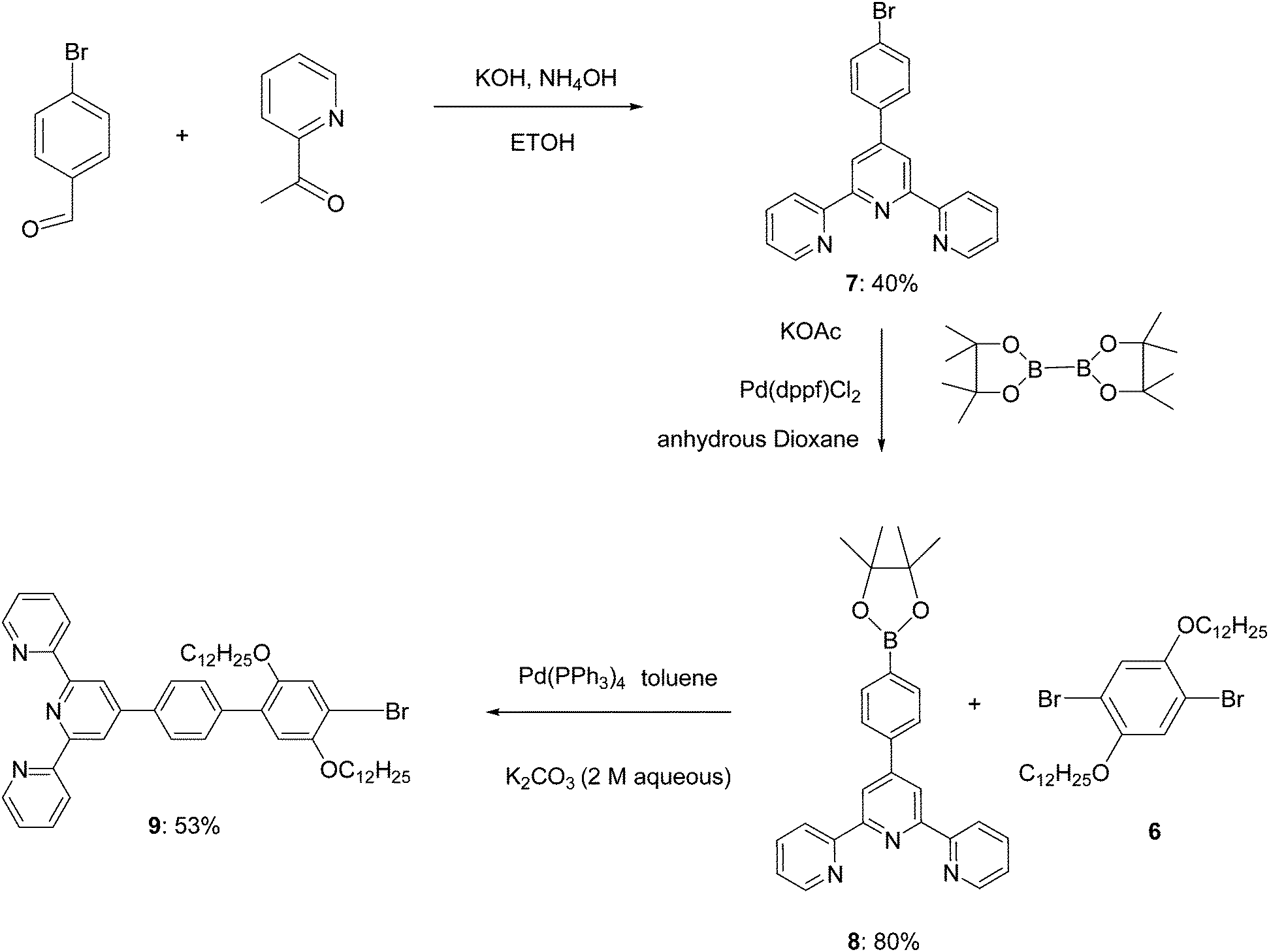
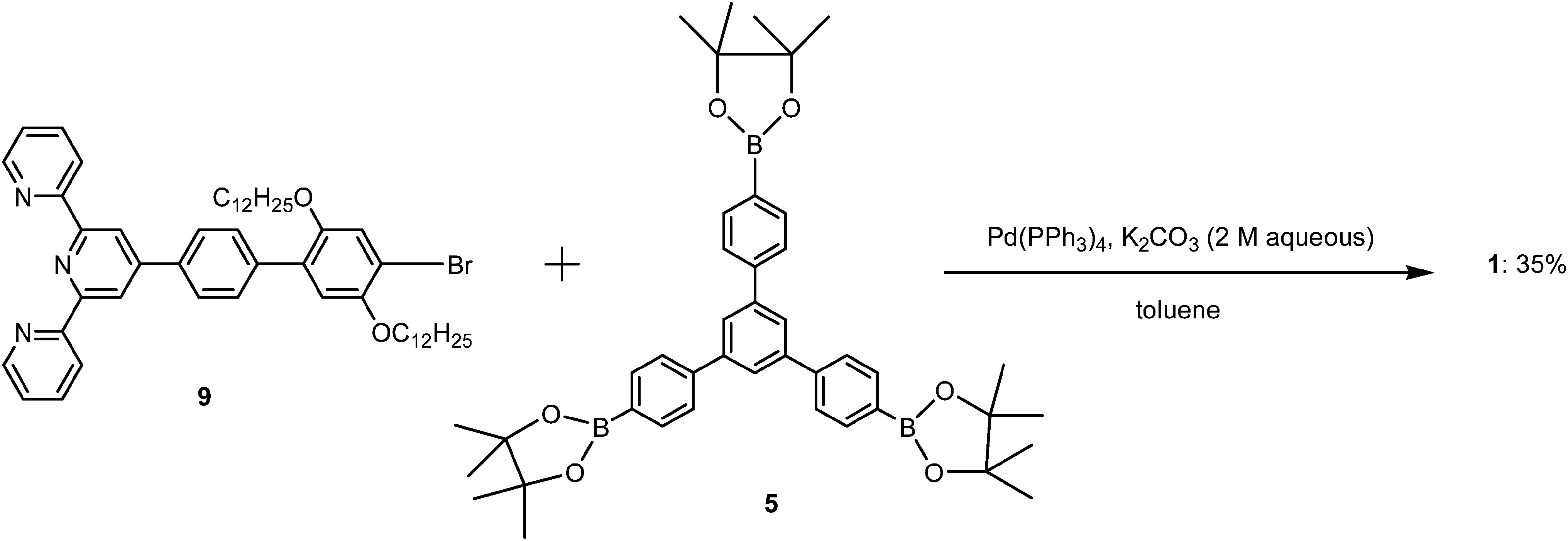
Boronation of molecule 4 through Suzuki coupling reaction gave the key intermediate core molecule 5 in a moderate yield.Synthesis scheme of this trigonal core molecule 5 is outlined in Scheme 1. In the next step towards synthesis of molecule 1, in the presence of Pd(0) catalyst, compound 9 was Suzuki-coupled with triborane 5 to produce compound 1 as an off white solid. The synthetic steps involved in the preparation of key intermediate molecule 9 and new 2D p-type core molecule 1 for 2D self-assembly are outlined in Schemes 2–4. The structure of this novel trigonal-tpy molecule 1 was confirmed by 1H NMR and 13C NMR and its molecular weight was confirmed by high resolution mass spectrometry (HRMS). 2D self-assembled networks of molecule 1 were made through zinc metal ion co-ordination.
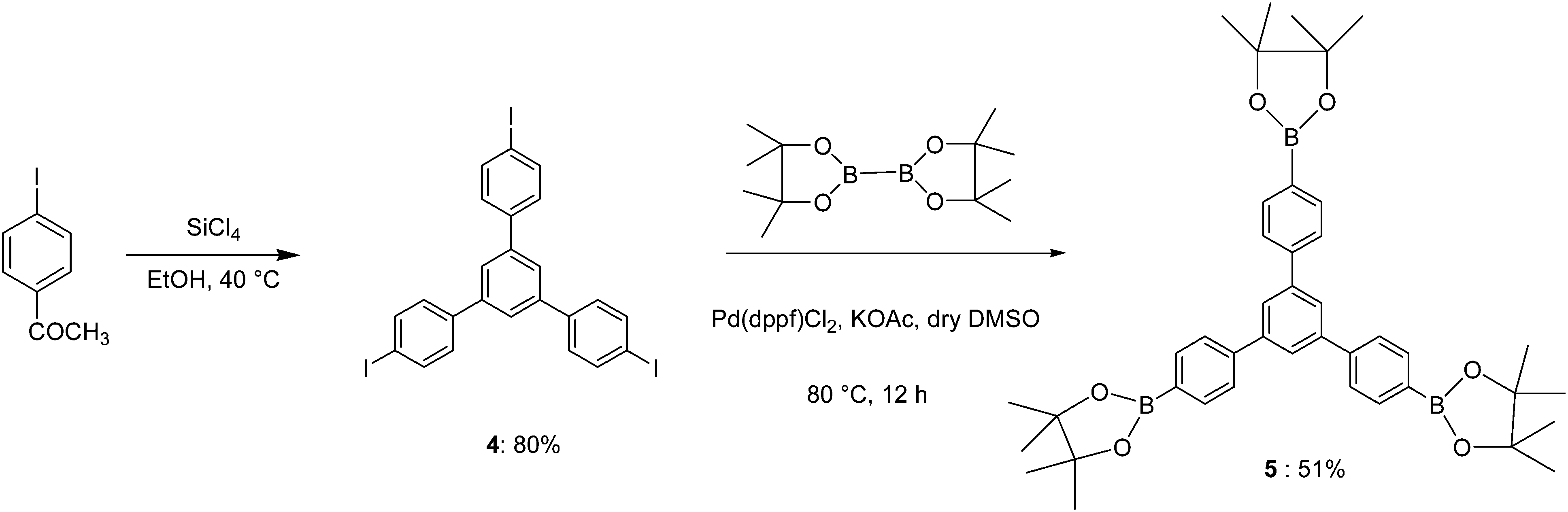 | ||
| Scheme 1 Synthetic route to trigonal molecule 5. | ||
 | ||
| Scheme 2 Synthetic route to molecule 6. | ||
 | ||
| Scheme 3 Synthetic route to key intermediate molecules 7, 8 and 9. | ||
 | ||
| Scheme 4 Synthesis scheme of 2D supramolecule 1. | ||
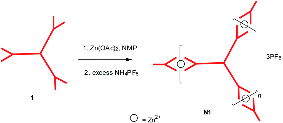
Formation of 2D Zn2+ co-ordinated self-assembled network N1 was obtained by refluxing its 2D monomers 1 with zinc acetate (Zn(OAc)2) at the stoichiometric ratio of 1![[thin space (1/6-em)]](https://www.rsc.org/images/entities/char_2009.gif) :1.5, in NMP solutions followed by anion exchange using an excess of NH4PF6. Although 2D monomer 1 is soluble in common organic solvents (e.g. ether, DCM, CHCl3, THF, etc.), the 2D networks N1–3 are not only insoluble in those common organic solvents but also in highly polar aprotic solvents (e.g. DMSO, DMF, NMP, acetonitrile etc.) at room temperature. This behaviour is believed to be caused by the highly cross linked or interpenetrated structure of the 2D networks. Therefore, all the unwanted byproducts (including any unreacted starting material 1) were washed away using ether to get the final network N1 in solid form. The formation of new 2D Zn2+ co-ordinated self-assembled supramolecular network N1 from trigonal tpy molecule 1 is shown in Scheme 5.
:1.5, in NMP solutions followed by anion exchange using an excess of NH4PF6. Although 2D monomer 1 is soluble in common organic solvents (e.g. ether, DCM, CHCl3, THF, etc.), the 2D networks N1–3 are not only insoluble in those common organic solvents but also in highly polar aprotic solvents (e.g. DMSO, DMF, NMP, acetonitrile etc.) at room temperature. This behaviour is believed to be caused by the highly cross linked or interpenetrated structure of the 2D networks. Therefore, all the unwanted byproducts (including any unreacted starting material 1) were washed away using ether to get the final network N1 in solid form. The formation of new 2D Zn2+ co-ordinated self-assembled supramolecular network N1 from trigonal tpy molecule 1 is shown in Scheme 5.
 | ||
| Scheme 5 Synthesis of one component 2D Zn2+ co-ordinated self-assembled supramolecular network N1. | ||
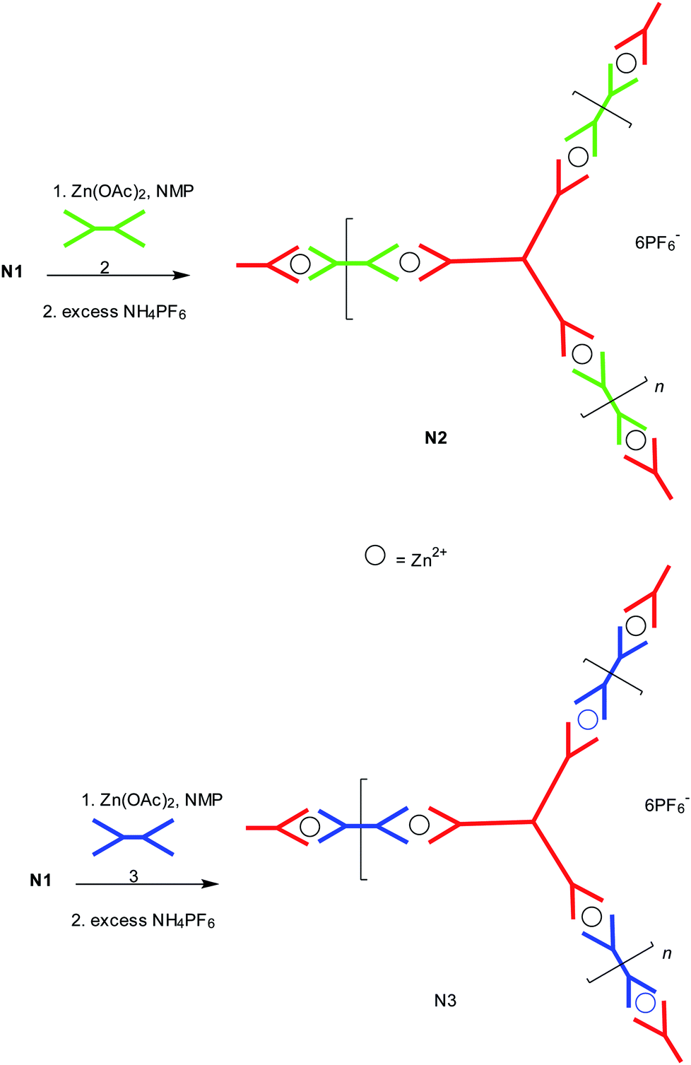
Using the method previously developed by us for making extended 3D networks,12 extended networks N2 and N3 were formed using the p-type or n-type conjugated tpy linker units 3 and 2 as shown in Scheme 6. 2,5-Bisdodecyloxy-p-phenylene has been employed as the p-type linker (3) in N3. Its being linear and electron rich, it is a good electron donor. In the other extended network N2, 2,1,3-benzothiadiazole (benzo[c][1,2,5]thiadiazole) has been used as the n-type linker (2) as it is known to be a good electron acceptor. The same insoluble behaviour was found for the 2D extended networks N2 and N3. Networks N2 and N3 were obtained by refluxing 2D network N1 with zinc acetate Zn(OAc)2 at the stoichiometric ratio of 1:1.5 in NMP solution to break the network, followed by inserting the linear bis(tpy) monomers 2 and 3 in between the 2D molecules, respectively, to form the 2D extended networks N2 and N3 after anion exchange using an excess of NH4PF6. After forming networks N2 and N3, any residual 2D starting monomer (1) and the linear bis(tpy) monomers (2 and 3) were washed away with ether.
 | ||
| Scheme 6 Synthesis of 2D Zn2+ co-ordinated self-assembled two component extended supramolecular networks N2 and N3. | ||
The concept of reversible self-assembly was demonstrated in these networks which confirmed our concept for their formation. By adding more metal ions into the 2D network N1, co-ordination complexes can be dissociated again in favour of an open form with each zinc ion only attached to one tpy unit and its other co-ordination sites presumably saturated by solvent molecules. Disassembly of N1 was followed by re-assembly to form extended 2D networks N2 and N3. 2D network N1 was only partially soluble in the NMP solution at 105 °C and the colour of solution was light brown at that moment, after adding 1.5 equivalents of Zn(OAc)2 in NMP, the insoluble solid gradually dissolved in the solution and the colour of solution gradually changed to light yellow before adding the linear bis(tpy) linkers. All these novel 2D Zn2+ co-ordinated self-assembled networks N1–3 were obtained in moderate yields (>50%).
Study of presence of Zn2+ ion in 2D network structures
X-ray photoelectron spectroscopy (XPS) studies were performed in order to achieve an insight into the network structures. XPS measurements were performed with monochromatic Al-K alpha radiation (1486.7 eV) to confirm the existence of the zinc metal-ions and to achieve more data in favour of the proposed network structures. XPS spectra of the zinc complexes on carbon tape substrates are shown in Fig. 2. The presence of Zn 2p photoemission peaks in N1, N2 and N3 confirms the Zn–ligand coordination. In contrast, no Zn 2p peak is present in starting material 1. In addition, the O 1s, C 1s, N 1s and F 1s peaks (may be due to PF6− counterions) are also shown in widescans, indicating a successful complexation of the terpyridine units. Due to low conductivity of three networks, a few eVs charging is observed and calibrated using C 1s and other photoemission peaks. The binding energy of Zn 2p in N1, N2 and N3 located at 1020.5 eV (N2) and 1021.3 eV (N1 and N3). The difference in binding energy could be either due to small residue charging or related to the different side chains of three networks.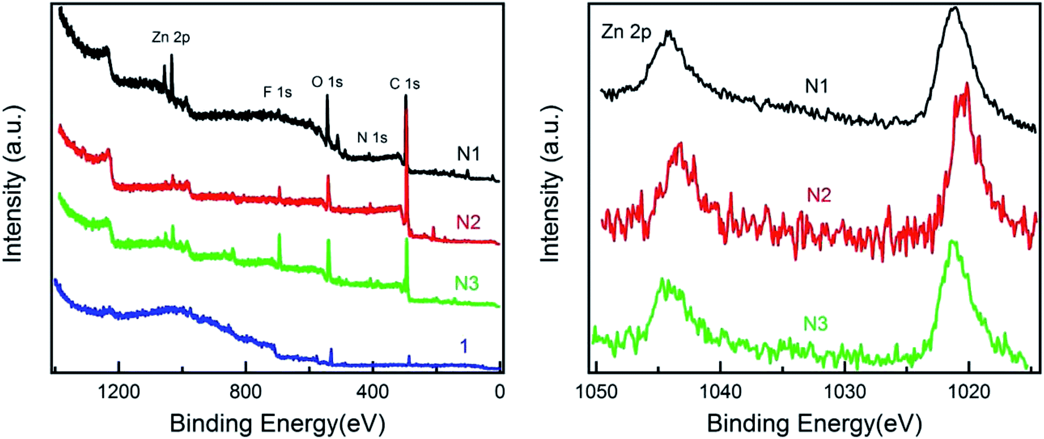 | ||
| Fig. 2 XPS spectra of 1 and its zinc complexes N1, N2 and N3 on a carbon tape. Wide-scan spectra and zinc 2p region. | ||
Molecular organization studies of 2D network structures
Small angle X-ray scattering (SAXS) was performed to study the molecular organization. SAXS for N1, N2 and N3 in the solid state are compared. As can be seen from Fig. 3, N1 has three clear broad peaks that centre at scattering vector q = 0.50 nm−1, 1.24 nm−1 and 2.46 nm−1 respectively. The peak at scattering vector q = 0.50 nm−1 ranges between 0.40 and 0.70 nm−1. This corresponds to a distance of 12.6 nm with a range between 9.0 and 15.7 nm. The peak at scattering vector q = 1.24 nm−1 ranges between 1.10 and 1.50 nm−1. This corresponds to a distance of 5.0 nm with a range between 4.0 and 5.7 nm. The peak at scattering vector q = 2.46 nm−1 exhibits a greater intensity and is relatively less broad than the other two peaks. It ranges between 2.00 and 3.10 nm−1. This corresponds to a distance of 2.5 nm with a range between 2.0 and 3.1 nm.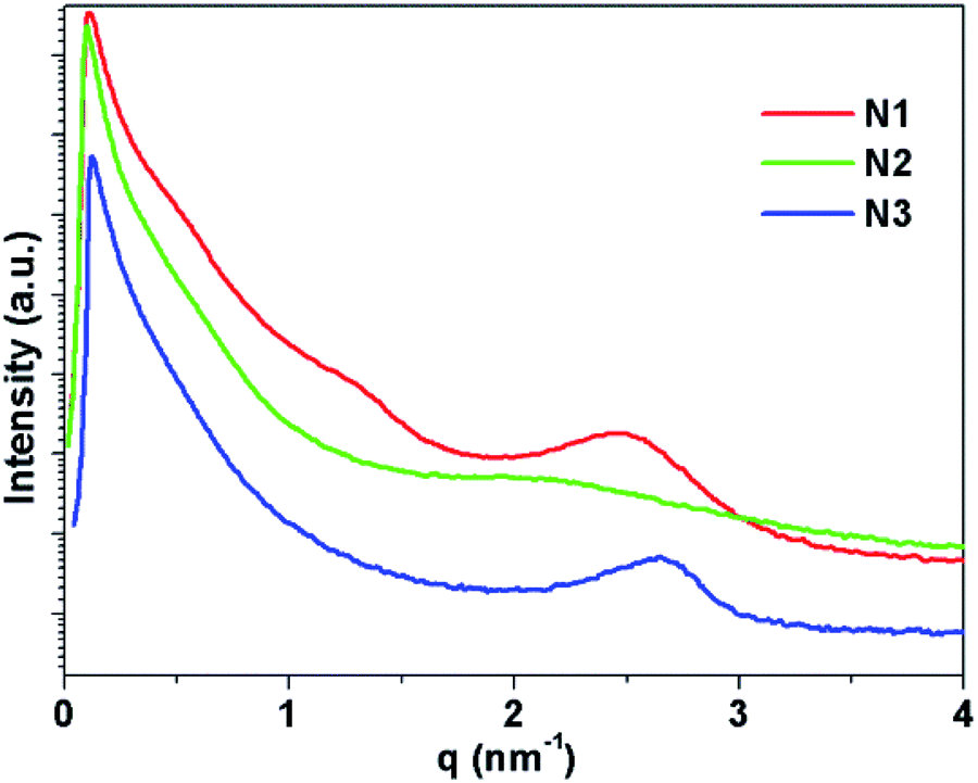 | ||
| Fig. 3 Powder SAXS diffractogram of 2D networks N1–3. | ||
N2 has two very broad weak peaks centred at scattering vector q = 0.38 nm−1 and 2.09 nm−1 respectively. The peak at scattering vector q = 0.38 nm−1 ranges between 0.3 and 0.5 nm−1. This corresponds to a distance of 1.65 nm with a range between 12.6 and 20.9 nm. The peak at scattering vector q = 2.09 nm−1 ranges between 1.00 and 3.10 nm−1. This corresponds to a distance of 3.0 nm with a range between 2.0 and 6.3 nm. N3 shows one broad but clear peak centred at scattering vector q = 2.66 nm−1 and ranges between 2.00 and 3.00 nm−1. This corresponds to a distance of 2.3 nm with a range between 2.1 and 3.0 nm. N1 shows three clear, although relatively broad, peaks compared to N2 and N3, which have fewer peaks that are both weaker and broader. This suggests that N1 has a more defined structure compared to N2 and N3. This reflects the single component self-assembly composition of N1, in contrast to N2 and N3, which are composed of two different basic building blocks and will contain a statistically random combination of each. Due to the insolubility of the networks we could not form films for study by STM or AFM as has been recently done for sheets of a similar network made by Schlüter et al.31 High resolution TEM images were obtained from deposits of N1 (see ESI†) on carbon coated copper grids but were unable to determine any structural data on the networks from them. Even with the use of electron energy loss spectroscopy (EELS) we were unable to see any peaks corresponding to the presence of zinc ions, which we attribute to the low concentration of the zinc in these networks.
Porosity studies
The porosity and the surface area of the 2D Zn2+ co-ordinated self-assembled networks N1–3 were investigated by sorption analysis using nitrogen. The results are shown in Fig. 4 and summarized in Table S1 in the ESI.† In comparison to the covalently bonded organic microporous networks based on tetraphenylmethane reported earlier,32–35 the surface areas of these networks are basically small (<2.1 m2 g−1). All the values are well within the experimental error of the equipment. The negative dip for these networks is believed to be due to small sample size. These materials are thus believed to be highly interpenetrating networks, and hence no porosity was found, in these 2D Zn2+ co-ordinated self-assembled networks. Similar results were reported12 for the 3D zinc metal ion co-ordinated networks with similar tpy branching units previously made by us. Shortening or removal of the long side chains is anticipated to solve this problem.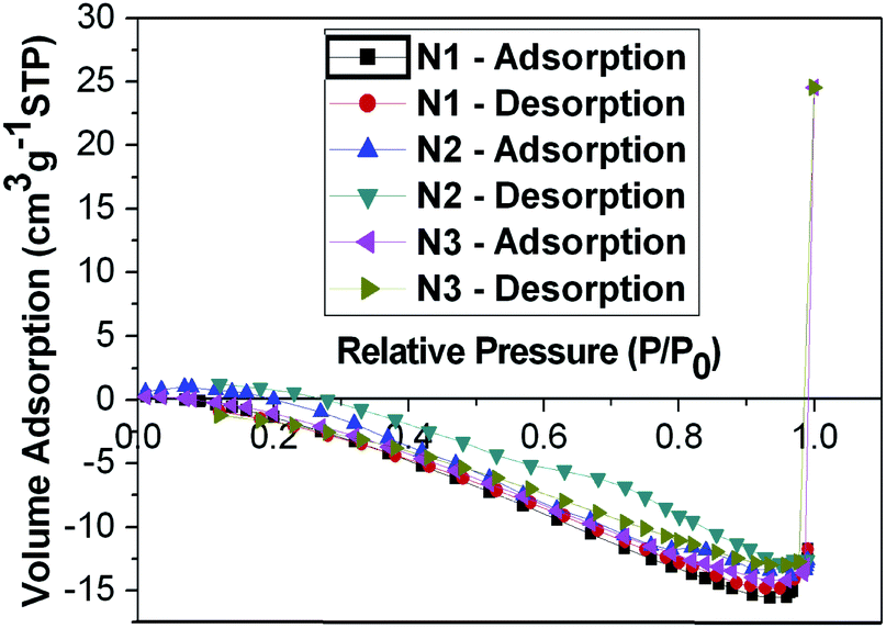 | ||
| Fig. 4 Nitrogen adsorption–desorption isotherms of 2D networks N1–3 measured at 77.3 K. | ||
Structural modelling of 2D self-assembled networks
Atomistic models for network materials have previously shown that the node-strut topology is highly influential on the resulting structural properties of the network and their ability to pack to fill space efficiently.32,33,36 Increased flexibility and conformational freedom of the network building blocks allow the networks to interpenetrate more freely and hence pack to fill more of the available space.33,36aFirstly, atomistic models of the building blocks, 1 and 3, and their respective one-component and two-component extended 3D self-assembled networks were generated. Models of 1 and 3 were fully optimised using the COMPASS force field37 in the Forcite module of Materials Studio 5.0 (ref. 38) with charges calculated using the Gasteiger method39 and are shown in Fig. 5. Assessing the optimised geometry of model of 1 shows that the structure deviates from the idealised planar form. There are three angles that can be defined between the centroid of the central phenyl and the central nitrogen atom of two of the tpy ligands for 1. These range between 103° and 138° compared to the ideal of 120°, and is 2 Å out of plane. The geometry of the optimised model for 3 shows a planar rigid molecule with the tpy-N–centroid–tpy-N angle being 177°.
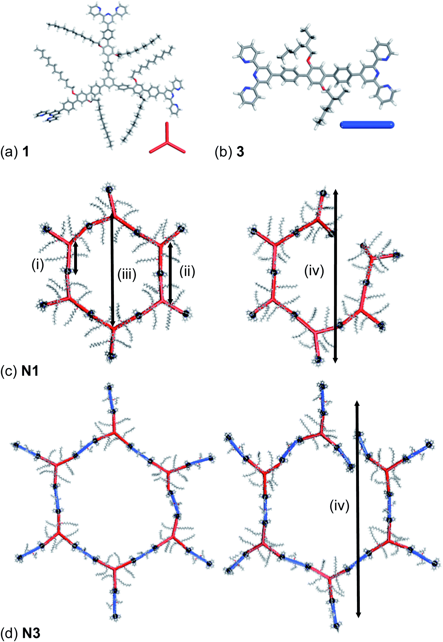 | ||
| Fig. 5 The optimised geometry of (a) 1 and (b) 3 and idealised hexagons and broken hexagons for (c) N1 and (d) N3 respectively showing the four types of repeating distances potentially present within the extended network. The red rod inset in (a) represents 1 in the extended networks. The blue rod represents 3 in N3. The black spheres represent the linking Zn2+. | ||
Using these idealised building units, we have rationalised the SAXS data discussed above. For N1, there are four distinct repeat units available. These are, in order of dimension, (i) the distance between the molecular centroid of 1 and a coordinated Zn2+, (ii) the molecular centroid – molecular centroid, and finally, depending upon the topology of the network either (iii) the molecular centroid – molecular centroid across a hexagonal repeat unit, if the network has a 2D graphite-like honeycomb structure, or (iv) a Zn2+ to opposite Zn2+ across a partial hexagonal ring, if the structure has a 3D structure. For N3, the two-component self-assembly results in a number of types of repeat units being available. These are the based on the same repeat units as identified for N1, but for each distinct repeat unit of N1, there are now a number of different combinations available for N3, particularly for repeat unit type (iii) where there will be multiple combinations possible. This variation in the build units results in the likelihood that these types will not be observed in SAXS measurements with only the build units of type (i) now being regular repeat units. These repeat units are identified in Fig. 5(c) and (d) for network N1 and N3 respectively.
A hexagonal and partial hexagon ring for both networks were generated for N1 and N3, shown in Fig. 5(c) and (d) for network N1 and N3 respectively and were fully optimised using the COMPASS force field37 in the Forcite module of Materials Studio 5.0 (ref. 38) with charges calculated using the Gasteiger method.39 For N1, the average distance between repeat units (i) and (ii) is 2.0 nm and 4.0 nm respectively, correlating well to the observed peaks which have corresponding distances centred on 2.5 nm and 5.0 nm. For the idealised hexagon ring the type (iii) distance is 8.0 nm, which does not correlate well with the final peak observed in the SAXS data centred at 12.6 nm. For the partial hexagon ring, the type (iii) distance is 12.0 nm, which correlates well with the final peak observed in the SAXS diffractogram centred at 12.6 nm. This suggests that hexagon rings are not a significant structural component of N1. For N3, the type (i) average distances measure 2.0 nm (same as for N1) and 2.4 nm, which correspond well with the peak centred at a distance of 2.3 nm. No further peaks are observed in the SAXS diffractogram for N3, suggesting that the structural components of type (ii), (iii) or (iv) and are not repeating in dimension. This also suggests that hexagon ring formation is not a significant structural component of N3. The lack of a hexagon ring component in both N1 and N3 further suggests that the building blocks, 1 and 3 are not rigid structurally-directing units but have some conformational flexibility.
To fully explore the conformational freedom of the two building blocks, we have used molecular dynamic simulation at 100 K and 298 K using the Forcite module, the COMPASS force field and charges assigned using the Gasteiger method and with an NPT ensemble. For each simulation, a total of 2 ns simulation time with a 1.0 fs time step was used. The angles and out-of-plane distance are monitored for the final 1 ns of each simulation for 1 and 3. For 1, the three angles range between 64° and 174°. One angle and the out-of-plane distance is monitored throughout the 298 K MD simulation showing an average angle of 111 ± 18° and an average out-of-plane distance of 6.4 ± 1.2 Å. It is noticeable that during the 298 K MD simulation the extended side chains wrap inwards towards the centre of the molecule. For 3, the tpy–centroid–tpy angle ranges between 158° and 180° through out-of plane and in-plane molecular bends with a distance of between 0 Å and 2 Å out of the molecular plane. This demonstrates the high degree of flexibility and conformational freedom available to both 1 and 3 network building blocks.
We then turned our attention to the automated generation of a 3D self-assembled network structure. The 3D self-assembled networks were broken into fragment building units; these are not necessarily chemically representative of the actual monomeric reactants but enable us to automate the building process. For N1, we used two basic building units, Fragments A and B, shown in Fig. S.11(a) and (c) respectively in ESI.† For Fragment A (based on 1), a library of 21 different conformers is available. This includes the idealised optimised structure and an additional 20 structures generated by sampling the two MD simulations. The MD simulations were sampled every 100000 steps and the geometry of the resulting structures were optimised before the tpy end groups were removed. The remaining three unsaturated carbon atoms of the terminal phenyl groups were assigned as bonding atoms. The distance between the bonding atoms and the molecular centroid is approximately 14.0 Å. Fragment B is generated from the Zn2+ and the tpy coordinating ligands with the two PF6− counter ions. The geometry of both the Zn2+-tpy and PF6− were fully optimised with DFT, using NWChem 6.1,40 a def2-tzvp basis set,41 B3LYP functional42 and incorporating the Grimme dispersion correction.43 A hydrogen atom is removed from the two central rings of each tpy group and the remaining unsaturated carbons were allocated as bonding atoms. The bonding atom – bonding atom distance is 9.7 Å. The incorporation of two PF6− groups within Fragment C ensures that these counter ions are accounted for within the network generation process. For N3, constructed from 1 and 3, we included an additional Fragment C (shown in Fig. S.11(b) in ESI†), which is generated from a library of 5 conformers which include the idealised structure and an additional four created by sampling the MD simulation of 3, similarly to 1. The terminal tpy groups were removed and the remaining unsaturated carbons on the terminal phenyl groups are allocated as bonding atoms. The distance between the bonding atoms of Fragment C is 11.5 Å. Representative structures for Fragments A, B, and C are shown in Fig. S.11(c)–(e)† respectively with the bonding atoms highlighted in yellow. For Fragments A and C, Fig. S.11 and S.12† shows an overlay of the library of structures available for each fragment.
A Python code was used to automate the generation of the self-assembled network. The code builds the network following pre-set rules for a series of building steps. The first step is a Seed step where one or more fragments are added to a simulation cell of pre-set dimensions. We assign rules as to which Fragments are permitted to bond as follows; for network N1, Fragment A can bond to Fragment B, but not A to A or B to B, similarly for network N3. Fragment A can bond to B but not A or C and Fragment C can bond to B but not C or A. A Build step bonds a randomly selected additional fragment to a randomly selected existing fragment or partially built network. The fragment is bonded with idealised bond lengths, although the torsional angles of the fragments about the bond are random. Additional bonds between fragments are only permitted if the bond geometry fits within the specified geometrical parameters, the bond distance is within a set range and no non-bonding atoms are closer than 1 Å. This ensures that the initial generation of the network is geometrically sensible.
We generated an idealised cluster for each network N1 and N3. This enables us to assess the presence of the idealised structural components and their respective dimensions within an extended structure. The idealised clusters are generated exclusively from the idealised models of 1 and 3, and do not include any of the structures obtained from the MD simulation. The idealised cluster for N3 was generated following the idealised alternating 1 and 3 building pattern. The clusters were generated by an initial Seed step with one randomly chosen fragment and then a series of Build steps following the bonding rules. Each cluster Fragment is capped with either an uncoordinated tpy or a H atom. After generation, the geometry of the cluster is optimised using the Fast Inertial Relaxation Engine (FIRE) rigid body minimiser within HOOMD-blue.44 The fragment build units are treated as rigid bodies so that only the bonds between fragments are optimised. The Intermolecular forces, bond and angle parameters are taken from the PCFF force field.45 Intermolecular forces are described using a Lennard-Jones potential with additional Zn2+ parameters.46 Charges are calculated using the Gasteiger method and QEq for the Zn2+ coordinated molecule in fragment B.39 The idealised clusters for N1 and N3 are shown in Fig. S.12(a) and (b)† respectively. There are structural features of type (iv), as described above, present in both idealised networks N1 and N3. For N1, the average is 11 nm and range between 10.0 nm and 14.4 nm, in good agreement with the range observed in the SAXs diffractogram for the peak centred at 12.6 nm with a range between 9 nm and 15.7 nm. For N3, the average is 16 nm and range between 19 nm and 14 nm. This does not correlate with any peaks in the diffractogram for N3. There are no structural components of type (iii) due to the automated network generation method. For N1, the type (i) and type (ii) are similar to the values obtained for the hexagon ring and for the partial ring. For the cluster model of idealised N3, the repeating structural components of type (ii) are well defined at 5.0 nm. We would expect to see peaks that correspond to both these distances in the SAXS diffractogram. These peaks are not present, with only peaks corresponding to the type (i) structural components present. This suggests that the regular alternating building unit model for N3 does not represent the real structure. An alternative model for N3 can be generated based on a randomised combination of the building block Fragments A and C.
Finally, we have constructed cluster models that include the structural flexibility observed in the MD simulations and randomised combination for N3. For N1 and N3 we have included the full library of structures for Fragment A and C. For network N3 the choice is random between Fragment A and C with an equal probability for either Fragment. A representative cluster is shown in Fig. 6(a) and (b) for N1 and N3 respectively also showing the underlying net and fragment combination. Five clusters were generated for each network and are shown in Fig. S.13.† The clusters of network N3 are largely planar, as might be expected from the two dimensionality of Fragment C, whereas those of N1 extend in all three dimensions. We see a wide range of different combinations of Fragment A and C leading to a very wide range of structural components. The only repeat units observed in the randomised clusters of N3 are those of type (i). This accounts for the absence of any peaks observed that do not correlate to type (i) distances within the SAXS diffractogram. Each cluster shows an extended structure with no evidence of order. The networks often turn in on themselves, suggesting that network interpenetration is likely. This suggests that an amorphous, efficiently packed solid will be formed with no porosity. This is in agreement with the porosity study discussed above.
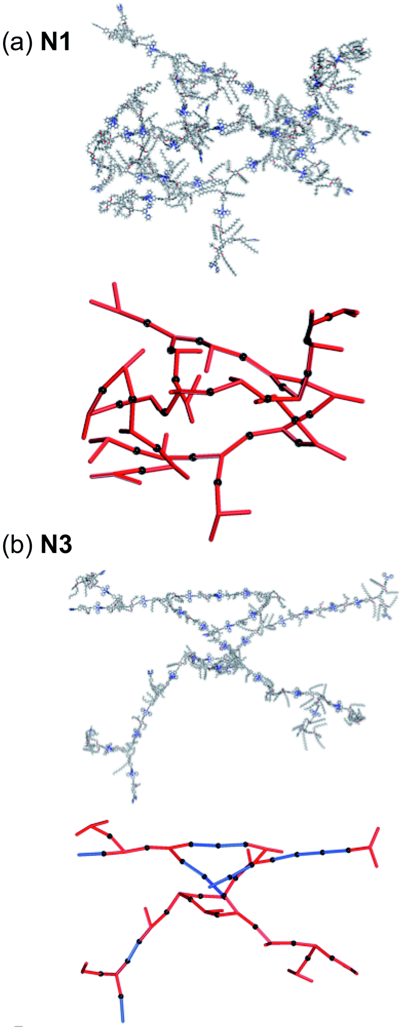 | ||
| Fig. 6 Extended networks of (a) N1 and (b) N3 generated through an automated method with random choice of building block. Right – the network showing all atoms and, left – the underlying network with 1 and 3 represented as red and blue rods respectively. The black spheres represent the linking Zn2+. The PF6− counter ions are omitted for clarity. | ||
Thermal behaviour of 2D self-assembled networks
Thermogravimetric analysis (TGA) plots and Differential Scanning Calorimetry (DSC) plots of core molecule 1 and its 2D networks N1–3 are shown in the ESI.† T5d, Tg and Tm of 2D networks N1–3 are listed in Table 1. According to Table 1, 2D zinc metal ion co-ordinated self-assembled networks N1–3 have slightly higher T5d compared to their respective starting materials 1. Besides that, N1–3 are generally more thermally stable compared to 1 as more than 50% of materials of N1–3 remain after heating to 900 °C. Thus, Zn2+ co-ordination helped to improve the thermal stabilities of these Zn2+ co-ordinated networks N1–3. But no phase transitions (Tg and Tm) were observed in the DSC measurements of N1–3. Also, these 2D Zn2+ co-ordinated self-assembled networks N1–3 are not crystalline as no significant exothermic peaks (Tc) have been observed during the heating cycles in their DSC plots.Comparison of optical properties of 2D and 3D self-assembled networks
Photophysical properties of 2D self-assembled networks N1–3 are in agreement with the observations for the terpyridine ligands and their 3D Zn2+ complexes discussed previously. Fig. 7(a) and (b) shows the appearance of self-assembled networks with naked eyes and under UV lamp respectively. The presence of Zn2+ ions in the molecular structure of the synthesized co-ordination networks N1–3 is clearly indicated by the observed red shifts in the recorded emission spectra as shown in Fig. 8. Furthermore, the emission spectra of the discussed systems (N1–3) were measured in solid state at room temperature. Molecules 1, 2 and 3 were emissive and the resulting Zn2+ co-ordination networks N1–3 were emissive too. The solid state optical properties of the networks can be adjusted by inserting different types of linkers into the extended networks. This aspect might be explained by the fact that the synthesized metallo-supramolecular networks tend to aggregate mainly due to the conjugated and rigid structure of the spacers (2 and 3) and as well as core molecule 1. Fig. 8 shows the emission spectra of core molecule 1 (emission peak at 436 nm) compared to the Zn2+ co-ordination networks N1–3 demonstrating the red shift of 82, 233, and 115 nm respectively. N2 shows red fluorescence under a UV lamp, as shown in Fig. 7, in comparison to the networks N1 and N3 both of which show yellow fluorescence under a UV lamp. This again shows the effect of the inserted n-type linker 2 which has a lower band gap and acts as sole emissive unit to produce red fluorescence in network N2, whereas, network N3 which has the p-type linker 3 shows similar emission to network N1. Hence it is apparent that after Zn2+ ion complexation with tpy ligands, the position of the emission peak changes significantly.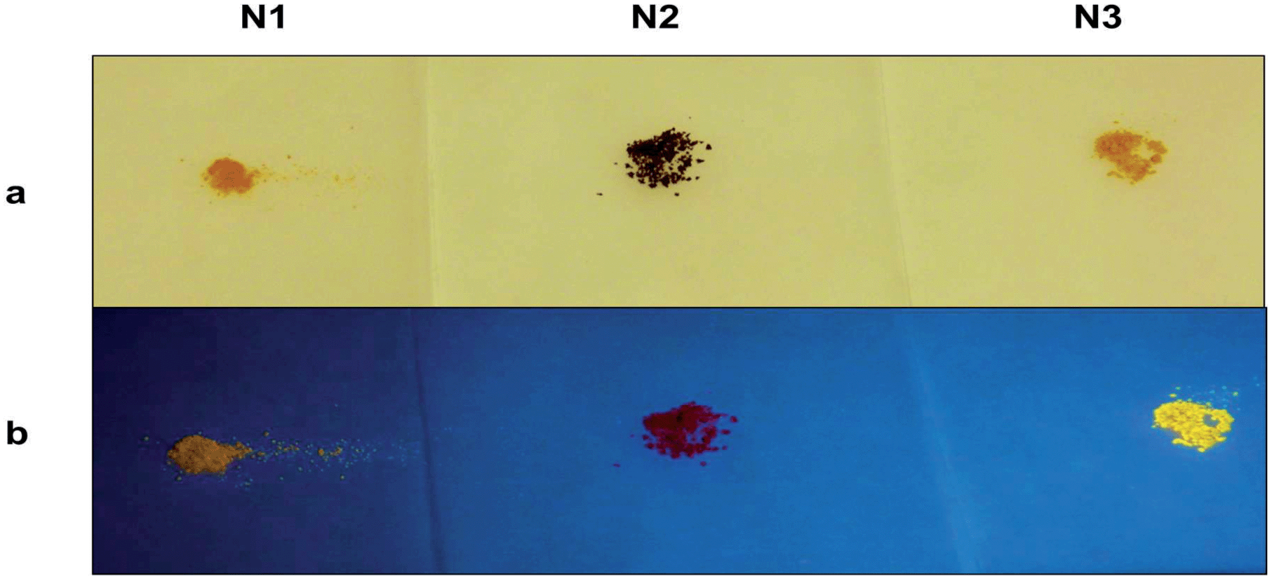 | ||
| Fig. 7 (a) Solid appearance and (b) solid fluorescence of 2D networks N1–3. | ||
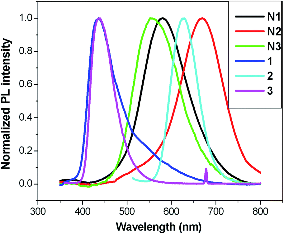 | ||
| Fig. 8 Solid state photoluminescence spectra of core molecules 1, 2, 3 and their 2D self-assembled networks N1–3. | ||
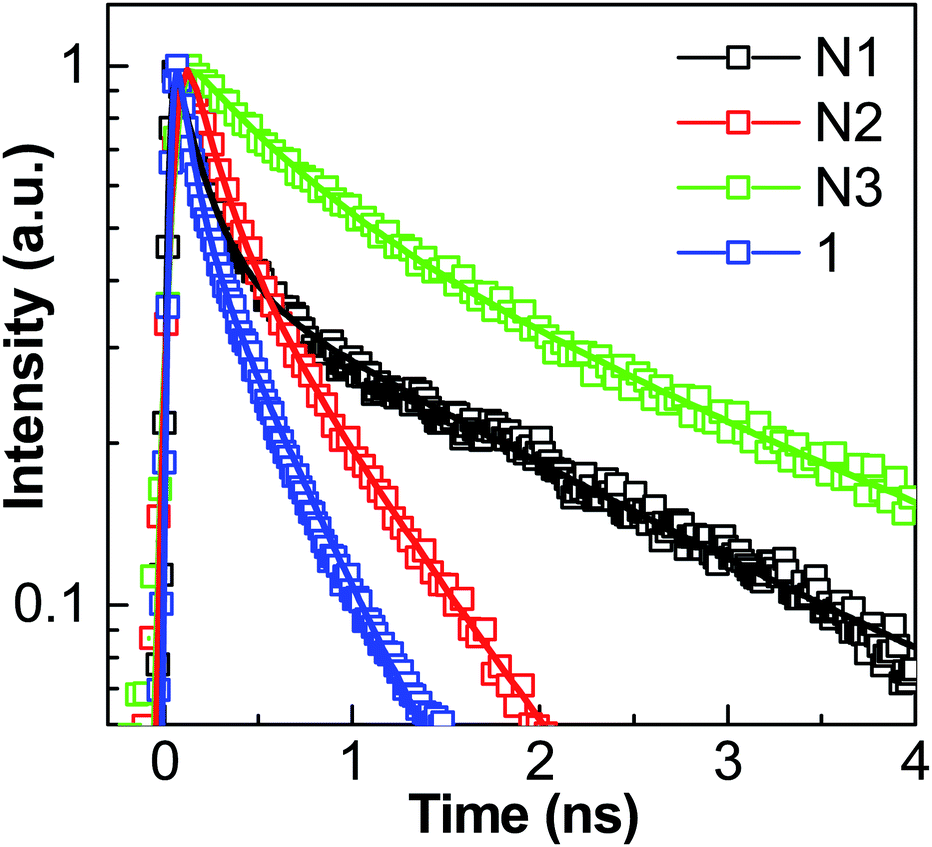
Moreover, it was expected that the Zn2+ tpy connectivity will increase the electron delocalization on the conjugated and rigid spacers, which can be observed by red shift in the PL spectra of N1–3. The reason behind the red shift in the emission spectrum is the increase in conjugation, which will increase the number of delocalized electrons in the system. Finally, the longer the value of conjugation length, the lower will be the energy gap between closest energy levels and the longer will be the absorption wavelength, and so the emission wavelength too. Femtosecond time-resolved photoluminescence dynamics of 1 and its self-assembled networks N1–3 and comparison with previously reported 3D networks has been performed. Fundamentally, fluorescence is a property of electronically excited states. Thus, fluorescence mechanisms can be better understood by time-resolved fluorescence spectroscopy. To obtain the dynamics of the PL spectra, the fluorescence lifetimes of compound 1 and its Zn2+ self-assembled networks N1–3 were measured. The fluorescence decay behavior in the presence of Zn2+ is shown in Fig. 9, with the exponential fit results. Table 2 shows the fitted lifetimes and the pre-exponential factors. For comparison, we have also calculated the average lifetime. Comparatively, molecule 1 was found to show a shorter lifetime compared to N1, N2 and N3. An increase in the fluorescence lifetime of networks N1–3 was observed after zinc meal ion co-ordination of trigonal and linear terpyridine moiety in 1, 2 and 3. Similar results were observed of networks S1 (similar to N1), S3 (similar to N3) and S4 (similar to N2) made up of a tetragonal tpy molecule (having similar branching units to trigonal tpy molecule 1) previously reported by us (see ESI†).12 The values of fluorescent life times are given in Table S1 in the ESI.† These results further suggest that networks with similar units have similar lifetime values. Enhancement in the lifetime after zinc metal ion co-ordination may be attributed to the increase in conjugation after metal complexation as observed with a red shift in the PL spectra too. These results also suggest a complete modification in the energy levels after zinc metal ion complexation. Networks N2 and S4 were formed by the n-type linker unit 2, which has a lower band gap. Hence the fluorescence lifetime of these networks are also lower compared to the results obtained for N1, S1, N3 and S3 which were formed by the p-type linker units.
 | ||
| Fig. 9 Time-resolved fluorescence decay of 1 and its self-assembled networks N1–3 in solid state. | ||
| Networks | A1 | τ1 (ns) | A2 | τ1 (ns) | τaverage (ns) |
|---|---|---|---|---|---|
| a An average lifetime, τa, was also calculated using τa = (A1τ12 + A2τ22)/(A1τ1 + A2τ2) for comparison. | |||||
| 1 | 0.56 | 0.10 ± 0.01 | 0.44 | 0.53 ± 0.02 | 0.45 ± 0.06 |
| N1 | 0.63 | 0.17 ± 0.01 | 0.37 | 2.16 ± 0.02 | 1.92 ± 0.07 |
| N2 | 0.60 | 0.19 ± 0.01 | 0.40 | 0.84 ± 0.01 | 0.68 ± 0.04 |
| N3 | 0.46 | 0.61 ± 0.01 | 0.54 | 2.75 ± 0.02 | 2.41 ± 0.06 |
Experimental
Palladium tetrakis (triphenylphosphine) Pd(PPh3)4 was purchased from Strem Chemicals. Other reagents and solvents were purchased from Alfa Aesar and Fisher Scientific and were used as received. All reactions were carried out under an inert N2 atmosphere. Analytical thin layer chromatography (TLC) was performed on aluminum sheets pre-coated with silica gel (with fluorescent indicator 254 nm). Visualization was accomplished with UV light. Purification of reaction mixtures using column chromatography was done on silica gel 60 Geduran (Merck). Nuclear magnetic resonance (NMR) spectra (1H and 13C) were recorded on a Bruker Advance 400 spectrometer, using magnetic field 400 MHz. Common solvents used in the NMR characterization were deuterated chloroform (CDCl3) and DCM (CD2Cl2) and. Coupling constants (J) are reported as Hertz (Hz). NMR splitting patterns are designated as s, singlet; d, doublet; dd doublet of doublets, t, triplet; and m, multiplet. Mass spectra were recorded using a Shimadzu Axima Matrix-assisted laser desorption/ionization time-of-flight (MALDI-TOF) mass spectrometer. Thermogravimetric analysis (TGA) experiments were performed on a TA TGA-Q500 with a dynamic heat rate (10 °C min−1) under nitrogen atmosphere (50 mL min−1) in the temperature range 25–800 °C. Differential scanning calorimetry (DSC) measurements were performed on a TA DSC-Q10 with dynamic heating and cooling rate (5 °C min−1) under nitrogen atmosphere (50 mL min−1) in the temperature range 0–200 °C.Synthesis of 1,3,5-tris(4-iodophenyl)benzene (4)
Compound 4 was synthesized as reported previously.47Synthesis of triboronate (5)
4 (684.09 mg, 1 mmol), bis(pinacolato)diborane (1.15 g, 4.5 mmol), potassium acetate (1.18 g, 12 mmol) and PdCl2(dppf) (65.85 mg, 0.09 mmol) were dissolved in anhydrous DMSO (15 mL) and then the solution was degassed under N2 atmosphere. The resulting solution was stirred at 80 °C for 12 h, cooled to RT, and then poured into ice water. The extraction of the resulting reaction solution was done with CHCl3 and water. Finally the CHCl3 layers were dried over anhydrous MgSO4. The solvent was evaporated with rotary evaporator; the residue was washed with cold hexane. Then the product was purified by recrystallization from MeOH–THF to afford 5 as an off-white solid (350 mg, 51%). 1H NMR (400 MHz, CDCl3): δ 7.93 (d, J = 8.2 Hz, 2H), 7.82 (s, 1H), 7.71 (d, J = 8.2 Hz, 2H), 1.37 (s, 12H).Synthesis of intermediates 6, 7 and 8
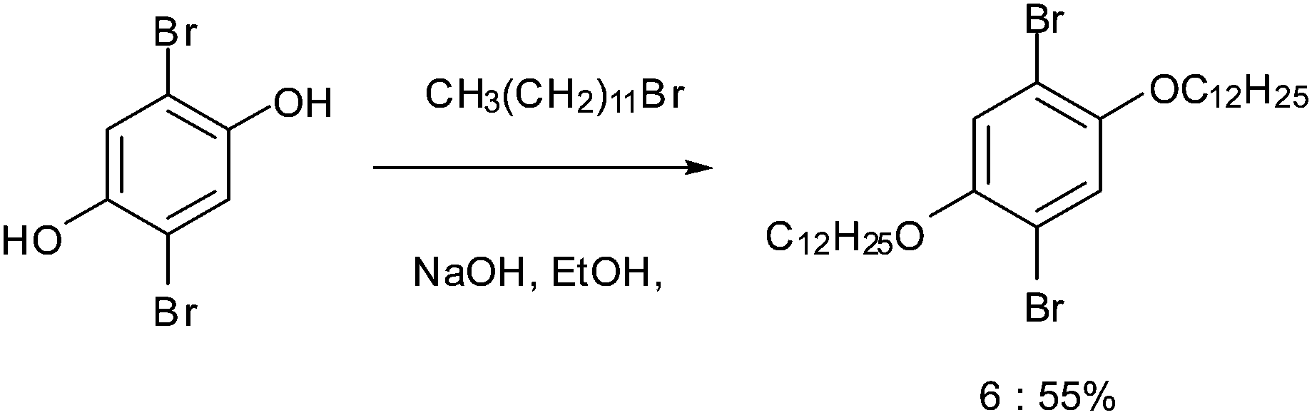
2,5-Dibromobenzene-1,4-diol (2,5-dibromohydroquinone) was dialkylated to form 1,4-dibromo-2,5-bis(dodecyloxy)benzene 6.48 4′-(4-Bromophenyl)-2,2′:6′2′′-terpyridine 7 was synthesized through the reaction of 4-bromobenzaldehyde and 2-acetylpyridine.49 The enolate of 2-acetylpyridine was produced by KOH under mild conditions, followed by an aldol condensation and a Michael addition. The intermediate, soluble diketone, was then permitted to form the central pyridine ring with an aqueous ammonia nitrogen source. Finally by boronation through a Miyaura reaction50 7 was converted to 4′-(4-pinacolatoboronphenyl)-2,2′:6′,2′′-terpyridine 8.Synthesis of linear tpy compound (9)
6 (10 g, 16 mmol), 8 (4.0 g, 9.20 mmol), and Pd(PPh3)4 (638 mg, 0.55 mmol) were degassed using N2 in a RBF. Degassed, THF (90 mL) and aqueous K2CO3 (2 M, 30 mL) were then injected into the RBF. The reaction mixture was then stirred in the dark at 80 °C for 24 h. After completion of the reaction (monitoring with TLC), the reaction mixture was cooled to RT and THF was removed using a rotary evaporator. The reaction mixture was then extracted with CH2Cl2. Organic layer was dried over MgSO4; solvent was removed by rotary evaporator. Finally the compound was purified by column chromatography on alumina eluting with 10% EA in hexane. The product 9 was obtained as a off-white solid (4 g, 53%). 1H NMR (400 MHz, CDCl3): δ 8.98 (s, 1H), 8.77 (t, J = 8.0 Hz, 2H), 8.03–7.94 (m, 2H), 7.69 (d, J = 8.0 Hz, 1H), 7.41 (t, J = 6.0 Hz, 1H), 4.03 (t, J = 6.0 Hz, 1H), 3.900 (t, J = 6.0 Hz, 1H), 1.84 (t, J = 8 Hz, 1H), 1.71 (t, J = 8 Hz, 1H), 1.51 (t, J = 8 Hz, 1H), 1.26–1.19 (br, 16H), 0.89–0.81 (m, 3H). Anal. calcd for C51H66BrN3O2: C, 73.54; H, 7.99; Br, 9.59; N, 5.04; O, 3.84%. Found: C, 73.80; H, 10.63; N, 4.97%. HR ES+-TOF MS: calculated m/z: 832.4417 (M+), found: m/z 832.4398 (M+).Synthesis of trigonal tpy compound (1)
5 (0.10 mmol, 68 mg), 9 (0.6 mmol, 500 mg) and Pd(PPh3)4 (0.010 mmol, 12 mg) were put into RBF and degassed using N2. Aqueous K2CO3 (2 M, 20 mL) and toluene (35 mL) were degassed using N2 and then injected into the RBF. The reaction mixture was then stirred in the dark at 90 °C for 72 h and monitored by TLC. The reaction mixture was cooled to RT and toluene was removed using a rotary evaporator. The resulting reaction solution was then extracted with CHCl3 and dried over MgSO4. Solvent was removed with rotary evaporator and the pure compound was obtained by column chromatography on alumina eluting with 25% EA in hexane. 1 was obtained as an off-white solid (90 mg, 35%). 1H NMR (400 MHz, CD2Cl2): δ 8.85 (s, 1H), 8.73 (dd, J = 11.4, 6.1 Hz, 2H), 8.05–7.72 (m, 12H), 7.70–7.48 (m, 1H), 7.46–7.32 (m, 3H), 7.17–7.09 (m, 2H), 4.02 (d, J = 5.8 Hz, 2H), 1.75 (s, 2H), 1.42 (s, 2H), 1.24 (d, J = 23.0 Hz, 16H), 0.84–0.80 (m, 3H). 13C NMR (101 MHz, CD2Cl2): δ 156.76, 156.64, 151.04, 149.77, 130.79, 130.69, 130.60, 128.38, 128.04, 127.45, 127.35, 124.47, 121.71, 119.10, 116.62, 116.46, 70.27, 54.00, 35.21, 32.49, 32.17, 30.23, 30.21, 29.93, 26.75, 25.82, 23.23, 14.45, 11.76. HR ES+-TOF MS: calculated m/z: 2562.6750 (M+), found: m/z 2562.6750 (M+).Synthesis of Zn2+-self-assembled network of 1 (N1)
To a solution of 1 (25 mg, 0.010 mmol) in NMP (10 mL), zinc(II) acetate dihydrate (4.2 mg, 0.015 mmol) in NMP (2 mL) was added dropwise. The resulting solution was then stirred at 105 °C under N2 atmosphere for 24 h. An excess of NH4PF6 was then added into the hot solution and stirring was continued for 30 min. The resulting reaction solution was added slowly into MeOH for precipitation. The precipitate was then filtered off and washed with MeOH. The precipitate was again dissolved in NMP followed by reprecipitation of the solid by adding ether. The precipitate was dried under vacuum for 24 h to give N1 as a yellow solid (27 mg, 74%).Synthesis of Zn2+ self-assembled network of 1 with 2 (N2)
N1 (15 mg, 0.005 mmol) in NMP (10 mL) was heated to 105 °C. Zn2+ acetate dihydrate (2.18 mg, 0.008 mmol) in NMP (2 mL) was added dropwise into the resulting solution. The reaction mixture was stirred at 105 °C under N2 for 1 h. 2 (9.63 mg, 0.0075 mmol, 1.5 times N1 moles) in NMP (10 mL) was then added dropwise and the resulting reaction mixture was stirred at 105 °C under N2 for 24 h. An excess of NH4PF6 was then added into the hot reaction mixture and stirring was continued for 30 min. The resulting reaction solution was added slowly into MeOH for precipitation. The precipitate was then filtered off and washed with MeOH. The precipitate was again dissolved in NMP followed by reprecipitation of the solid by adding ether. The precipitate was dried under vacuum for 24 h to give N2 as a red solid (14 mg, 62%).Synthesis of Zn2+-self-assembled network of 1 with 3 (N3)
N1 (15 mg, 0.005 mmol) in NMP (10 mL) was heated to 105 °C. Zn2+ acetate dihydrate (2.2 mg, 0.0075 mmol) in NMP (2 mL) was added dropwise into the reaction mixture. The reaction mixture was stirred at 105 °C under N2 for 1 h. 3 (7.2 mg, 0.0075 mmol, 1.5 times N1 moles) in NMP (10 mL) was then added dropwise and the resulting reaction mixture was stirred at 105 °C under N2 for 24 h. An excess of NH4PF6 was then added into the hot reaction mixture and stirring was continued for 30 min. The resulting reaction solution was added slowly into MeOH for precipitation. The precipitate was then filtered off and washed with MeOH. Precipitate was again dissolved in NMP followed by reprecipitation of the solid by adding ether. The precipitate was dried under vacuum for 24 h to give N3 as a yellow solid (12 mg, 55%).Spectroscopic characterizations
For the measurements of photoluminescence (PL) spectra, a cw He–Cd laser emitting at 325 nm was used as the excitation source and the signals were dispersed by a 750 mm monochromator combined with suitable filters, and detected by a photomultiplier using the standard lock-in amplifier technique. Time-resolved photoluminescence (TRPL) spectroscopy was performed using 325 nm laser pulses generated from an optical parametric amplifier parametric amplifier (Light Conversion TOPAS) that was pumped by a 1 kHz regenerative amplifier (Coherent Legend; center wavelength: 800 nm; pulse width: 150 fs; power: 1 mJ per pulse), which was in turn seeded by an 80 MHz Coherent Vitesse oscillator. The TRPL signals were collected in a typical backscattering geometry by a pair of lenses to a DK240 1/4 m monochromator with 300 g mm−1 grating, and the temporal evolution of the PL was resolved by an Optronis Optoscope streak camera system. The streak camera system has an ultimate temporal resolution of ∼10 ps when operated at the shortest time window of 330 ps.Conclusions
Synthesis and characterization of various Zn2+ terpyridine 2D self-assembled networks were described in this work. Their thermal and photophysical properties were studied in detail and compared to the constituent chelating terpyridine ligands. These 2D co-ordination networks are found to be thermally stable as compared to their starting materials, especially at very high temperature due to the effect of zinc metal ion co-ordination.2D Zn2+ supramolecular networks were compared to the 3D Zn2+ networks in order to understand the influence of the Zn2+ ions on the photophysical properties of the designed structures. The synthesized 2D Zn2+ co-ordination networks revealed marked red shifts in the emission spectra like the 3D Zn2+ networks made up of similar building blocks. It was observed that the presence of the Zn2+ ions in the synthesized model complexes revealed interesting spectroscopic properties, in particular, enhanced fluorescence and fluorescence life time. Thus, from the experimental results it was concluded that the characteristics of the basic building units are considerably influencing the photophysical properties of the Zn2+ co-ordination networks. Such Zn2+ systems could be potentially interesting for the construction of optoelectronic devices.
Acknowledgements
We acknowledge the financial support, including the award of a Research Student Scholarship to D.R., from the Singapore Ministry of Education through the Academic Research Fund Tier 1 (SUG 40/06 and RG19/07) and also from the National Research Foundation through Competitive Research Project 5-2009-04 “Towards Efficient Sunlight Harvesting”. A.T holds a Royal Society fellowship. We thank Dr Zviad Tsakadze and Miss Anantha P. from the School of Materials Science and Engineering, NTU for performing SAXS and TEM measurements respectively.Notes and references
- H. Hofmeier and U. S. Schubert, Chem. Soc. Rev., 2004, 33, 373 RSC.
- S. Burattini, H. M. Colquhoun, J. D. Fox, D. Friedmann, B. W. Greenland, P. J. F. Harris, W. Hayes, M. E. Mackay and S. J. Rowan, Chem. Commun., 2009, 6717 RSC.
- F. Cacialli, P. Samorì and C. Silva, Mater. Today, 2004, 7, 24–32 CrossRef CAS.
- S. De Feyter and F. C. De Schryver, Chem. Soc. Rev., 2003, 32, 139–150 RSC.
- A. Langner, S. L. Tait, C. Rajadurai, M. Ruben and K. Kern, Chem. Commun., 2007, 4860–4862 Search PubMed.
- T. Chen, G.-B. Pan, H. Wettach, M. Fritzsche, S. Höger, L.-J. Wan, H.-B. Yang, B. H. Northrop and P. J. Stang, J. Am. Chem. Soc., 2010, 132, 1328–1333 CrossRef CAS PubMed.
- R. Chakrabarty, P. S. Mukherjee and P. J. Stang, Chem. Rev., 2011, 111, 6810–6918 CrossRef CAS PubMed.
- T. Chen, G.-B. Pan, H. Wettach, M. Fritzsche, S. Höger, L.-J. Wan, H.-B. Yang, B. H. Northrop and P. J. Stang, J. Am. Chem. Soc., 2010, 132, 1328–1333 CrossRef CAS PubMed.
- O. Ivasenko, J. M. MacLeod, K. Y. Chernichenko, E. S. Balenkova, R. V. Shpanchenko, V. G. Nenajdenko, F. Rosei and D. F. Perepichka, Chem. Commun., 2009, 1192 RSC.
- M. Ruben, U. Ziener, J. M. Lehn, V. Ksenofontov, P. Gütlich and G. Vaughan, Chem.–Eur. J., 2004, 11, 94–100 CrossRef CAS PubMed.
- T. Bauer, A. Schlüter and J. Sakamoto, Synlett, 2010, 877–880 CAS.
- Z. B. Lim, H. Li, S. Sun, J. Y. Lek, A. Trewin, Y. M. Lam and A. C. Grimsdale, J. Mater. Chem., 2012, 22, 6218 RSC.
- Y. Ohba, K. Kanaizuka, M. Murata and H. Nishihara, Macromol. Symp., 2006, 235, 31–38 CrossRef CAS.
- L. J. Liang, X. J. Zhao and C. Z. Huang, Analyst, 2012, 137, 953 RSC.
- X. Zhou, X. Jin, D. Li and X. Wu, Chem. Commun., 2011, 47, 3921 RSC.
- X. Chen, Q. Zhou, Y. Cheng, Y. Geng, D. Ma, Z. Xie and L. Wang, J. Lumin., 2007, 126, 81–90 CrossRef CAS PubMed.
- S.-H. Hwang, C. N. Moorefield, P. Wang, J.-Y. Kim, S.-W. Lee and G. R. Newkome, Inorg. Chim. Acta, 2007, 360, 1780–1784 CrossRef CAS PubMed.
- A. Winter, C. Friebe, M. Chiper, M. D. Hager and U. S. Schubert, J. Polym. Sci., Part A: Polym. Chem., 2009, 47, 4083–4098 CrossRef CAS.
- T. He, D. Rajwar, L. Ma, Y. Wang, Z. B. Lim, A. C. Grimsdale and H. Sun, Appl. Phys. Lett., 2012, 101, 213302 CrossRef PubMed.
- D. W. Fink and W. E. Ohnesorge, J. Phys. Chem., 1970, 74, 72–77 CrossRef CAS.
- U. S. Schubert, C. Eschbaumer, O. Hien and P. R. Andres, Tetrahedron Lett., 2001, 42, 4705–4707 CrossRef CAS.
- X. Yan, F. Wang, B. Zheng and F. Huang, Chem. Soc. Rev., 2012, 41, 6042–6065 RSC.
- A. Wild, A. Winter, F. Schlütter and U. S. Schubert, Chem. Soc. Rev., 2011, 40, 1459–1511 RSC.
- A. Wild, C. Friebe, A. Winter, M. D. Hager, U. W. Grummt and U. S. Schubert, Eur. J. Org. Chem., 2010, 2010, 1859–1868 CrossRef.
- G. R. Newkome, Science, 2006, 312, 1782–1785 CrossRef CAS PubMed.
- A. L. Kanibolotsky and P. J. Skabara, Chem. Soc. Rev., 2010, 39, 2695–2728 RSC.
- V. Duprez, M. Biancardo, H. Spanggaard and F. C. Krebs, Macromolecules, 2005, 38, 10436–10448 CrossRef CAS.
- C. J. Kuehl, S. D. Huang and P. J. Stang, J. Am. Chem. Soc., 2001, 123, 9634–9641 CrossRef CAS PubMed.
- B. H. Northrop, Y.-R. Zheng, K.-W. Chi and P. J. Stang, Acc. Chem. Res., 2009, 42, 1554–1563 CrossRef CAS PubMed.
- A. D'Aléo, E. Cecchetto, L. De Cola and R. M. Williams, Sensors, 2009, 9, 3604–3626 CrossRef PubMed.
- Z. Zheng, C. S. Ruiz-Vargas, T. Bauer, A. Rossi, P. Payamyar, A. Schütz, A. Stemmer, J. Sakamoto and A. D. Schlüter, Macromol. Rapid Commun., 2013, 34, 1670–1680 CrossRef CAS PubMed.
- J.-X. Jiang, F. Su, A. Trewin, C. D. Wood, N. L. Campbell, H. Niu, C. Dickinson, A. Y. Ganin, M. J. Rosseinsky, Y. Z. Khimyak and A. I. Cooper, Angew. Chem., Int. Ed., 2007, 46, 8574–8578 CrossRef CAS PubMed.
- J.-X. Jiang, F. Su, A. Trewin, C. D. Wood, H. Niu, J. T. A. Jones, Y. Z. Khimyak and A. I. Cooper, J. Am. Chem. Soc., 2008, 130, 7710–7720 CrossRef CAS PubMed.
- T. Tozawa, J. T. A. Jones, S. I. Swamy, S. Jiang, D. J. Adams, S. Shakespeare, R. Clowes, D. Bradshaw, T. Hasell, S. Y. Chong, C. Tang, S. Thompson, J. Parker, A. Trewin, J. Bacsa, A. M. Z. Slawin, A. Steiner and A. I. Cooper, Nat. Mater., 2009, 8, 973–978 CrossRef CAS PubMed.
- Q. Chen, M. Luo, T. Wang, J.-X. Wang, D. Zhou, Y. Han, C.-S. Zhang, C.-G. Yan and B.-H. Han, Macromolecules, 2011, 44, 5573–5577 CrossRef CAS.
- (a) J. Jiang, A. Trewin, F. Su, C. D. Wood, H. Niu, J. T. A. Jones, Y. Z. Khimyak and A. I. Cooper, Macromolecules, 2009, 42, 2658–2666 CrossRef CAS; (b) E. Stockel, X. Wu, A. Trewin, C. D. Wood, R. Clowes, N. L. Campbell, J. T. A Jones, Y. Z. Khimyak, D. J. Adams and A. I. Cooper, Chem. Commun., 2009, 212–214 RSC.
- H. Sun, J. Phys. Chem. B, 1998, 102, 7338–7364 CrossRef CAS.
- Accelrys, Materials Studio 5.0, San Diego, CA, 2009 Search PubMed.
- J. Gasteiger and M. Marsill, Tetrahedron, 1990, 36, 3219–3228 CrossRef.
- M. Valiev, E. J. Bylaska, N. Govind, K. Kowalski, T. P. Straatsma, H. J. J. Van Dam, D. Wang, J. Nieplocha, E. Apra, T. L. Windus and W. A. de Jong, Comput. Phys. Commun., 2010, 181, 1477–1489 CrossRef CAS PubMed.
- F. Weigend and R. Ahlrichs, Phys. Chem. Chem. Phys., 2005, 7, 3297–3305 RSC.
- (a) A. D. Becke, J. Chem. Phys., 1993, 98, 5648–5652 CrossRef CAS PubMed; (b) C. Lee, W. Yang and R. G. Parr, Phys. Rev. B: Condens. Matter Mater. Phys., 1988, 37, 785 CrossRef CAS.
- S. Grimme, J. Antony, S. Ehrlich and H. Krieg, J. Chem. Phys., 2010, 132, 154104–154119 CrossRef PubMed.
- (a) J. A. Anderson, C. D. Lorenz and A. Travesset, J. Comput. Phys., 2008, 227, 5342–5359 CrossRef PubMed; (b) T. D. Nguyen, C. L. Phillips, J. A. Anderson and S. C. Glotzer, Comput. Phys. Commun., 2011, 182, 2307–2313 CrossRef CAS PubMed; (c) http://codeblue.umich.edu/hoomd-blue, HOOMD-blue web page.
- (a) H. Sun, S. J. Mumby, J. R. Maple and A. T. Hagler, J. Am. Chem. Soc., 1994, 116, 2978–2987 CrossRef CAS; (b) H. Sun, Macromolecules, 1995, 28, 701–712 CrossRef CAS; (c) H. Sun, J. Comput. Chem., 1994, 15, 752–768 CrossRef CAS.
- J. Torras and C. Aleman, J. Phys. Chem. B, 2013, 117, 10513–10522 CrossRef CAS PubMed.
- S. Kotha, D. Kashinath, K. Lahiri and R. B. Sunoj, Eur. J. Org. Chem., 2004, 2004, 4003–4013 CrossRef.
- C. Baskar, Y.-H. Lai and S. Valiyaveettil, Macromolecules, 2001, 34, 6255–6260 CrossRef CAS.
- J. Wang and G. S. Hanan, Synlett, 2005, 1251–1254 CAS.
- C. J. Aspley and J. A. Gareth Williams, New J. Chem., 2001, 25, 1136–1147 RSC.
Footnote |
| † Electronic supplementary information (ESI) available: NMR, CV, TGA, DSC, TEM and mass spectral data for new compounds and networks. Structures, PL profiles and PL data for S1, S3 and S4, molecular model for 1, 3, N1, and N3. See DOI: 10.1039/c3ra47377e |
| This journal is © The Royal Society of Chemistry 2014 |