Xiao Yuan Chenab,
Hoang Vinh-Thanga,
Denis Rodrigue*a and
Serge Kaliaguinea
aDepartment of Chemical Engineering, Université Laval, Québec, Canada G1V 0A6. E-mail: Denis.Rodrigue@gch.ulaval.ca; Fax: +1-418-656-5993; Tel: +1-418-656-2903
bCentre National en Électrochimie et en Technologies Environnementales, Collège Shawinigan, Shawinigan, Canada G9N 6V8
First published on 18th February 2014
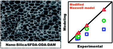
Macrovoid structured mixed matrix membranes (MMMs) composed of nano-size (200 nm) silica particles and co-polyimide were prepared from 6FDA–ODA–DAM (6FDA = 4,4′-(hexafluoroiso-propylidene)diphthalic anhydride; ODA = 4,4′-oxidianiline; DAM = 1,3,5-trimethyl-2,6-phenylenediamine) with different proportions (1
:
1 and 1
:
4) and tetraethoxysilane (TEOS) via the sol–gel method. The separation performance of MMMs with 6FDA–ODA–DAM treated at high temperature (450 °C) was excellent for CO2/CH4 separation (for 6FOD–ODA–DAM (1
:
1): CO2 permeability ∼265 Barrer and CO2/CH4 selectivity ∼32; for 6FOD–ODA–DAM (1
:
4): CO2 permeability ∼302 Barrer and CO2/CH4 selectivity ∼25). Remarkably, the best membrane could resist pressure up to 600 psi without any loss of permselectivity. The CO2/CH4 separation performance of a series of silica–6FDA–ODA–DAM(11) MMMs with different SiO2 loadings is theoretically predicted using a modified Maxwell model where both gas permeability and macrovoid shape factor are simultaneously considered as adjustable parameters. Applying the optimized values, the modified Maxwell model predictions were in excellent agreement with experimental permeability data (less than 2% deviation).
For example, Iwata et al. reported that by using the sol–gel method, a nanocomposite membrane of polyacrylonitrile (PAN) with hydrolyzate of tetraethoxysilane (TEOS) as the inorganic phase showed O2 permeability of 2.2–2.5 Barrer and ideal selectivity of 13–17 (silica contents from 3–20 wt%) in O2/N2 separation.31
Gomes et al. prepared poly(1-trimethylsilyl-1-propyne) (PTMSP)/silica nanocomposite membranes by sol–gel copolymerization of TEOS with different organoalkoxysilanes in tetrahydrofuran solution of PTMSP.32
Joly et al. fabricated polyimide/silica membranes containing 32 wt% silica via the sol–gel method by adding tetramethoxysilane (TMOS) to poly(amic acid) (PAA) solution and subsequently imidizing at 60–300 °C. The nanocomposite membrane had a higher permeability for CO2 (from 0.8 to 2.0 Barrer) and a lower CO2/CH4 selectivity (from 40 to 25) compared to the pure polyimide membrane.21
Kusakabe et al. reported that CO2 permeability of polyimide/SiO2 hybrid nanocomposite membranes was 15 times larger than that of the corresponding polyimide. Permeability also increased with increasing mass fraction of silica, while permselectivity of CO2 to N2 decreased.33
Suzuki et al. reported that hyperbranched polyimide (HBPI)–silica hybrid membranes were prepared via a sol–gel technique using poly(amic acid), water, and tetramethoxysilane.24,34,35 Amine-terminated 6FDA–TAPOB hyperbranched polyimide (HBPI) (HBPI(6FDA-TAPOB)) was prepared by polycondensation of 1,3,5-tris(4-aminophenoxy) benzene (TAPOB) and 6FDA in N,N-dimethylacetamide (DMAc), followed by an addition of a silane coupling agent, 3-aminopropyl-trimethoxysilane (APTrMOS) to modify the end groups.24,34 6FDA-HAB hydroxy polyimide (HPI) (HPI(6FDA-HAB)) was synthesized from 6FDA and 3,3′-dihydroxybenzidine (HAB) in DMAc. Finally, 6FDA-TAPOB hyperbranched polyimide (HBPI(6FDA-TAPOB))/6FDA-HAB hydroxy polyimide (HPI(6FDA-HAB)) blend-silica hybrid membranes were prepared by blending HBPI and HPI polymers, adding of appropriate amounts TMOS and deionized water, followed by imidizing and hybridizing in an oven under N2 flow.35 The results showed that both gas permeabilities and CO2/CH4 selectivities were increased with increasing silica content.
Recently, Suzuki et al. used the same method to obtain hyperbranched polyimide-silica hybrid membranes followed by heat-treatment in nitrogen at 450 °C. These membranes have both excellent gas permeability (134–369 Barrer) and selectivity (32–68), particularly for CO2/CH4 under the tested conditions (76 cm Hg and 25 °C).36
Fardad studied the influence of various catalysts on the structure of silica sol–gel films based on the hydrolysis and condensation of TEOS with 2 moles of water, and in the presence of 2 moles of ethanol. This investigation showed that film thickness, shrinkage, porosity, and optical quality depended on the type of catalysts used in the preparation of the solution precursor.37
Kayser et al.38 prepared amine functionalized nano-spherical silica particles by a modified Stöber method39 and grafted 3-aminopropyl-dimethylmethoxysilane (APDMS) on their surface. These particles were used as inorganic fillers in silica/SPEEK mixed matrix membranes. The results indicated that the main effect of the inorganic filler on proton conductivity is related to changes in the microstructure of the water channels in the wet polymer related to the distribution of nanoparticles in their lattice.
In the above-described investigations, most authors prepared the silica particles in situ in acid conditions (for example, poly(amic acid) (PAA)), with the acid acting as a catalyst in the hydrolysis/condensation reactions. In some cases, silica particles were first produced and then mixed with polymer solution before casting. The polymer morphology changes associated with particle introduction in the MMMs, and their effects on membrane performance in gas separation were seldom discussed. In this work, silica particles were simultaneously generated with membrane fabrication by a simple method. The focus is made on the relationship between morphology, affected by silica particles, and membrane separation performances of the MMMs in CO2/CH4 separation.
:
DAM molar ratios are 1
:
1 and 1
:
4) were prepared by solution condensation in NMP. Both reaction mixtures were stirred using a power drill (Mastercraft) connected to a variable autotransformer (The Superior Electric co. Bristol Conn, USA) stirrer under an argon atmosphere and placed in an ice–water mixture for 15 h. In the second step, poly(amic acid) was then imidized to form polyimides by chemical imidization under an argon atmosphere at room temperature for 24 h by adding acetic anhydride (dehydrating agent) and triethylamine (catalyst). The reaction scheme of co-polyimide synthesis is shown in Fig. 1. The polyimide solution was then precipitated with methanol, washed several times with methanol, and dried at 200 °C in a vacuum oven for 24 h.
![]() | (1) |
| Si(OC2H5)4 + 2H2O → SiO2 + 4C2H5OH | (2) |
The weight loss curves (TGA-DTG) were recorded using a TA Instruments TGA model Q5000IR from 100 to 850 °C at a heating rate of 10 °C min−1 under nitrogen.
The glass transition temperature (Tg) and Young's modulus of MMM were determined using a dynamic mechanical thermal analyzer (TA Instruments, RSA-3, New Castle, DE) on samples having dimensions of 25 × 6 × 0.02 mm3. For Tg measurements, the temperature was increased from 30 to 350 °C at a rate of 10 °C min−1 with a strain of 0.05% and a frequency of 1 Hz.
The membrane density (ρ) is simply defined by the ratio between mass (M) and volume (V). The mass is weighed with an analytical balance Mettler AE200 with a sensitivity of 10−4 g. The volume is then calculated from the diameter (d) (constant at 55 mm) and the average of 8 thicknesses (l) of the membrane.
SEM images were recorded to determine crystal size and to characterize morphology of the dispersed phase, using a JEOL JSM-840A operated at 15–20 kV. From the SEM micrographs, the average diameter of macrovoids, their number and surface were obtained using image analysis software (Image Pro Plus). The average diameter was measured at 2 degree intervals and passing through the centroid giving an average of 90 measurements for each macrovoid.
The cell density is determined from the number of cells per unit section area. It is calculated assuming that the surface distribution is the same in all three dimensions and eqn (3) is the mathematical expression of cell density.41
![]() | (3) |
For the transport of individual components A and B through a membrane, the permeability Pi of penetrant i can be expressed as follows:
![]() | (4) |
The ideal selectivity can be written as the ratio of permeabilities:
![]() | (5) |
The separation factor (α*AB) represents the ability of a membrane to separate a binary gas mixture, and is defined as:
| α*AB = (yA/yB)/(xA/xB) | (6) |
:
DAM molar ratio is labelled 11 or 14 (for 1
:
1 and 1
:
4, respectively). For example: 6FOD(11)-n%-200, n% is wt% SiO2 loading, and 200 is the treatment temperature. The treatment temperatures are 200, 300 and 450 °C. The temperatures to reach 5% and 10% weight loss of 5–15 wt% SiO2/polyimide MMMs were increased (by about 5–30 °C). Those of MMMs after thermal treatment at 300 and 450 °C were generally lower by about 10–40 °C. DTG peak temperatures also give information on the pyrolysis rates. Thermal stability of the MMM materials prepared via TEOS hydrolysis reaction is believed to be sufficient for gas separation applications, even through the stability value is very close compared to that of the pure polyimide.42 For example, the highest temperature used for hydrogen separation was 300–500 °C. At the natural gas well, the gas pressure is rather high (in excess of 1000 psi) and the gas temperature is on the order of 30–50 °C. All the TGA curves show a plateau, which indicates no remnant hydroxyl groups. There was no residual absorbed solvent or hydroxyl group having low decomposition temperature. At the latter temperature, most chemical decomposition reactions of the material took place. These weight losses are mostly due to the conversion of carbonyl groups (C
O) to either CO or CO2.43
| Membranea | Td5% (°C) | Td10% (°C) | DTG peak (°C) |
|---|---|---|---|
a 6FOD(11), 6FOD(14) : 6FDA-ODA-DAM (1 : 1) and 6FDA-ODA-DAM (1 : 4). n%: wt% SiO2 loading, at treatment temperature of 200, 300 and 450 °C. |
|||
| 6FOD(11)-0%-200 | 488 | 508 | 529 |
| 6FOD(11)-5%-200 | 495 | 529 | 550 |
| 6FOD(11)-10%-200 | 501 | 531 | 553 |
| 6FOD(11)-15%-200 | 504 | 535 | 554 |
| 6FOD(11)-10%-300 | 450 | 511 | 549 |
| 6FOD(11)-10%-450 | 503 | 532 | 552 |
| 6FOD(14)-0%-200 | 489 | 508 | 523 |
| 6FOD(14)-10%-200 | 447 | 484 | 520 |
| 6FOD(14)-10%-300 | 451 | 484 | 520 |
| 6FOD(14)-10%-450 | 464 | 485 | 520 |
| Matrimid-0%-200 | 474 | 508 | 511 |
| Matrimid-10%-200 | 440 | 486 | 518 |
| Matrimid-10%-450 | 452 | 492 | 523 |
As shown in Fig. 2, the appearance of absorption bands at 1725 cm−1 (asymmetric stretch of the carbonyl group, imide I band) and 1782 cm−1 (symmetric stretch of the carbonyl group, imide II band), 1377 cm−1 (C–N stretch), 1117 cm−1 (imide III band) and 720 cm−1 (deformation of the imide ring or imide IV carbonyl group) confirmed the formation of imides for all membranes.44 Usually, siloxanes show one or more very strong infrared bands in the region 1000–1130 cm−1. Disiloxane and small-ring cyclosiloxanes show a single Si–O–Si band. As the siloxane chains became longer or branches the Si–O–Si absorption becomes broader and more complex showing two or more overlapping band.45 From Fig. 2, carbonyl (C
O) peaks were found at 1100 cm−1 in the 6FOD(11) membrane, silica (Si–O) vibrations are found between 1080 and 1060 cm−1 in the others membrane. The 6FOD(11)-20%-ambient has two peaks at 1060–1080 cm−1. Thus these peaks to some extent overlap with the C–O frequencies of polyimides. Other weak vibrations are found in between 2900 and 3000 cm−1 in Fig. 2 for membrane 6FOD(11)-20% at ambient temperature. This membrane is the nascent film and was not heated. These distinctive bands at 2927–2983 cm−1 correspond to the symmetric and asymmetric vibrations of CH2 methylene and CH3 methyl groups. It is thought that these groups belong to the ethanol generated in reaction (2).
Table 2 summarizes the glass transition temperature and Young's modulus of 6FOD(11) polyimide, and 6FOD(11) with TEOS MMM. Compared to the neat 6FOD(11) membrane (Table 2), the Tg values of MMMs decreased with increasing MOF loading (from 5 to 20 wt%). This decrease might be explained by the presence of macrovoids (see below), which can enhance the movement of the polymer chains. In the preparation of polymer foams, carbon dioxide and ethanol (EtOH) mixtures can be used as blowing agents as already proposed.47,48 Gendron at al. studied the effect of blending CO2 with ethanol (EtOH) as a co-blowing agent for polystyrene (PS) foaming.48 The results showed that viscosity and glass transition temperature obviously decreased with increasing amount of foaming agents. The Tg values of treated MMMs are higher than that of the neat polyimide membrane. This may be due to polymer chains becoming more rigid after rearrangement upon high temperature treatment.49 Moreover, Young's modulus of MMM membranes decrease with increasing SiO2 loading (Fig. 3 and Table 2). This behaviour is usually associated with highly reduced densities and low mechanical properties of foamed polymers.50
| Membrane | Tg (°C) | Young's modulus (MPa) (50 °C) |
|---|---|---|
| 6FOD(11)-0%-200 | 319 | 150 |
| 6FOD(11)-5%-200 | 318 | 67 |
| 6FOD(11)-10%-200 | 317 | 66 |
| 6FOD(11)-15%-200 | 305 | 48 |
| 6FOD(11)-20%-200 | 283 | 31 |
| 6FOD(11)-10%-300 | 327 | 56 |
| 6FOD(11)-10%-450 | 353 | 72 |
![]() | ||
| Fig. 4 SEM micrographs showing the macrovoid structure of 6FOD(11)-200 MMMs with: (a) 5 wt%; (b) 10 wt%; (c) 15 wt%, and (d) 20 wt% SiO2 loading. | ||
Fig. 5 shows the distribution of macrovoid average diameter in each membrane. Table 3 summarizes the membrane density, average macrovoid diameter and macrovoid density of MMMs. Membrane density was decreased slowly with increasing SiO2 loading compared with the original membrane. The average macrovoid diameter and macrovoid density changed with SiO2 loading. The morphology of macrovoid structure is complex and could be affected by many factors during membrane fabrication such as ambient temperature, pH value of solution, stirring time, etc. These results are consistent with higher void size and lower void number as reported in ref. 48.
![]() | ||
| Fig. 5 Macrovoid average diameter distribution of MMMs: (a) 6FOD(11)-5%-200; (b) 6FOD(11)-10%-200; (c) 6FOD(11)-15%-200, and (d) 6FOD(11)-20%-200. | ||
| Membrane | Membrane density (g cm−3) | Average diameter (μm) | Macrovoid density (cm−3) |
|---|---|---|---|
| 6FOD(11)-0%-200 | 1.38 | — | — |
| 6FOD(11)-5%-200 | 1.08 | 5.95 | 2.0 × 10⁷ |
| 6FOD(11)-10%-200 | 1.06 | 7.45 | 1.3 × 10⁷ |
| 6FOD(11)-15%-200 | 0.71 | 4.48 | 1.0 × 10⁸ |
| 6FOD(11)-20%-200 | 0.51 | 5.27 | 3.9 × 10⁷ |
| 6FOD(11)-10%-300 | 0.79 | 4.02 | 3.0 × 10⁷ |
| 6FOD(11)-10%-450 | 0.96 | 5.04 | 3.5 × 10⁷ |
The size of silica particles was dependent on the conditions of hydrolysis solution.39 In the present work, 200 nm silica particles were observed for MMM in very weak acid solution. Fig. 6 shows an example for 6FOD(11)-10%-200 membrane. This result is in agreement with ref. 39.
![]() | ||
Fig. 6 SEM images of SiO2 particles of 6FOD(11)-10%-200 membrane with different magnifications: (a) 10 000×; and (b) 20 000×. | ||
| Membrane | PCO2 (Barrer) | PCH4 (Barrer) | PCO2/PCH4 | (50/50%) CO2/CH4 mixed gas selectivity |
|---|---|---|---|---|
| 6FOD(14)-0%-200 | 130 | 7.10 | 23.2 | 22.9 |
| 6FOD(14)-10%-200 | 290 | 21.8 | 13.3 | 21.8 |
| 6FOD(14)-10%-450 | 300 | 12.2 | 24.8 | 22.3 |
| Matrimid-0%-200 | 10.0 | 0.28 | 35.3 | 35.0 |
| Matrimid-10%-200 | 41.0 | 1.10 | 38.0 | 38.0 |
| Matrimid-10%-450 | 34.0 | 0.92 | 36.7 | 38.2 |
| Ultem-0%-200 | 1.45 | 0.037 | 38.8 | 36.8 |
| Ultem-10%-200 | 2.78 | 0.15 | 17.5 | 18.2 |
Two co-polyimides with different ODA
:
DAM (1
:
1 and 1
:
4) molar ratios were used as polymer matrices for macrovoid structured MMMs. The CO2/CH4 separation performances of neat and their macrovoid structure membranes are summarized in Tables 4 and 5. The co-polyimide 6FOD(14) with 10 wt% SiO2 has both higher values of CO2 and CH4 permeability compared to those of neat co-polyimide. The macrovoid membranes of 6FOD(14)-10%-450 and 6FOD(11)-10%-450 with heating temperature of 450 °C showed very high CO2 permeability of 302 and 265 Barrer, and their selectivity improved to 24.8 and 32 from 23 and 24, respectively. The separation factor for mixed gas also showed high values from 22 to 34.
| Membrane | PCO2 (Barrer) | PCH4 (Barrer) | PCO2/PCH4 | (50/50%) CO2/CH4 mixed gas selectivity |
|---|---|---|---|---|
| 6FOD(11)-0%-200 | 51.8 | 1.80 | 24.2 | 21.9 |
| 6FOD(11)-5%-200 | 200 | 12.5 | 18.2 | 24.5 |
| 6FOD(11)-10%-200 | 235 | 12.5 | 16.8 | 24.6 |
| 6FOD(11)-15%-200 | 420 | 76.9 | 6.3 | — |
| 6FOD(11)-20%-200 | 810 | 695 | 1.2 | — |
| 6FOD(11)-10%-300 | 245 | 13.1 | 18.7 | 25.7 |
| 6FOD(11)-10%-450 | 265 | 8.6 | 31.8 | 34.2 |
Coupling a theoretical modelling with experimental separation data provides an opportunity to understand the transport properties of these MMMs. As reported in our recent review,52 the particularly useful Maxwell model developed in 1873, originally derived from the estimation of the dielectric properties of particulate composite materials, has been widely accepted as a simple and effective tool for predicting permeation properties of a two-phase ideal MMM as:
![]() | (7) |
In eqn (7), Peff describes the effective steady-state permeability of a gaseous penetrant through a MMM, Pf and Pc are the effective permeability of pure filler membrane and polymer matrix, respectively, ϕd is the volume fraction of the dispersed filler.52,53 In this equation, Pc and ϕd are often known experimental parameters, while Pf can be considered as either an un-known or a known parameter. The shape factor n depends on the shape of the dispersed filler. Various definitions of n were proposed in the literature. Hamilton and Crosser have, for example, proposed n = 3/ψ, where the sphericity ψ is defined as the ratio between the surface area of a sphere having a volume equal to the particle volume and the particle surface area.54 For near-spherical fillers, the value is therefore taken as n = 3, and eqn (7) reduces to the well-known original Maxwell model.53 Kang et al. reported a shape factor n = 6 for cylindrical or tubular fillers in a polymer matrix.55 In this case, eqn (7) is an expression of the Hamilton-Crosser model.54 For a general case of filler shape, the shape factor n can accept a variety of integer values up to infinity.54
It is clear that in order to mathematically solve eqn (7), both the shape factor n and the filler permeability Pf can be considered as adjustable parameters and optimized by minimizing the differences between experimental data and calculated ones. This difference, namely the average absolute relative error (%AARE), is expressed as follows:
![]() | (8) |
![]() | (9) |
Generally, gas permeability in the interfacial void (Pv) of a typical zeolite-polymer MMM is assumed to be the product of Knudsen diffusivity through a pore with the same hydraulic diameter as the void and sorption coefficient of the gas in the void.52,54 In the present case, because of the mean free paths (λ) of penetrant gas (λCO2 = 0.082 μm and λCH4 = 0.062 μm calculated based on ref. 56 at 25 °C and 15 psi) are much smaller than the average macrovoid diameter (Table 3), the gas transport through the macrovoids is assumed to be by molecular or bulk diffusion.57 Thus, coupling with the shape factor n, the macrovoid permeability Pv will be considered as adjustable parameters. First, all the macrovoid MMMs with different SiO2 loadings were assumed to have the same shape factor n and macrovoid permeability Pv. After calculating the membrane permeability PM using eqn (9), the average absolute relative error (%AARE) was then determined using eqn (8). The optimized value of Pv corresponding to the average shape factor navg was obtained for the minimum value of %AARE. Second, owing to a large difference in macrovoid diameter of these silica-6FOD MMMs (see Fig. 4 and Table 3), an optimized shape factor n must be determined for each MMM membrane. This is obtained by using eqn (8) and (9), but only the shape factor n is considered as an adjustable parameter while Pv has the value determined in the previous step. Table 6 summarizes the estimated model parameters obtained from Maxwell model fitting the experimental data of CO2/CH4 separation through the silica-6FOD(11) MMMs with different SiO2 loadings.
| Membrane | ϕv (vol%) | Pv (Barrer) | navg | nop | PCO2 (Barrer) | %AARE | |||||
|---|---|---|---|---|---|---|---|---|---|---|---|
| Exp. | n = 3 | n = 6 | nop | n = 3 | n = 6 | nop | |||||
| 6FOD(11)-5%-200 | 24 | 3185 | 11 | 11 | 200 | 98 | 139 | 197 | 53.9 | 29.3 | 1.3 |
| 6FOD(11)-10%-200 | 28 | 12 | 235 | 107 | 156 | 237 | |||||
| 6FOD(11)-15%-200 | 53 | 8 | 420 | 209 | 339 | 414 | |||||
| 6FOD(11)-20%-200 | 67 | 11 | 810 | 326 | 537 | 798 | |||||
As can be seen in Table 6, the value of the optimized CO2 permeability of macrovoids Pv predicted by the Maxwell model using our MATLAB optimization program is 3815 Barrer. Compared to the CO2 permeability values calculated based on the Knudsen diffusion for a void space with average diameter of 5 nm (15
200 Barrer) or a pinhole with average diameter of 50 nm (152
000 Barrer),54 this value is significantly smaller, although the average macrovoid diameters of the studied MMMs are ranging from 4.58 to 7.45 μm (Table 3). This result confirms the above assumption for the gas diffusion mechanism through the macrovoids.
Fig. 10 illustrates a comparison between the CO2 permeability predicted by the Maxwell model with different shape factors n and the experimental data. Both n = 3 (spherical) and n = 6 (cylindrical or tubular) show a significant divergence with the experimental data. Their %AAREs are 53.9 and 29.3%, respectively. Interestingly, better agreement between the Maxwell model predictions and experimental data was observed when applying the optimized shape factors nop (%AARE = 1.3%, see Table 6).
The relation between macrovoid diameter and shape factor n is demonstrated in Fig. 11. The optimized shape factor nop is a linear function of the average macrovoid diameter. This result is remarkably significant for the application of the Maxwell model to predict the gas permeation performance of any kind of MMM morphology.
A special use of shape factor n in the Maxwell equation was developed to predict the gas transport properties through MMMs for this new macrovoid MMM morphology. This work is an additional step to our recent comprehensive computational strategy to fit experimental permeation data of MMMs.58 In this study, the modified Maxwell model predictions were in excellent agreement with experimental data having less than 2% deviation. Both intrinsic gas permeability of the dispersed phase (macrovoid) and shape factor (n) were simultaneously considered. The shape factor (n) was found to be strongly dependent on the foam-like morphology of these MMMs.
| This journal is © The Royal Society of Chemistry 2014 |