A facile bi-phase synthesis of Fe3O4@SiO2 core–shell nanoparticles with tunable film thicknesses

Jian Zou*, Yun-Gui Peng* and Yi-You Tang
School of Chemistry and Chemical Engineering, Southwest University, Chongqing, 400715, P. R. China. E-mail: ezouj@swu.edu.cn; pyg@swu.edu.cn

Received 26th November 2013 , Accepted 28th January 2014

First published on 28th January 2014


Abstract

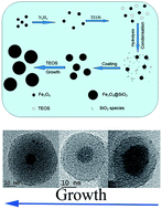
Monodisperse Fe3O4@SiO2 nanoparticles are prepared using hydrazine as a catalyst via a biphase approach without any alcohols or surfactants. Fe3O4 seeds can be dispersed well in this system. The sizes of Fe3O4@SiO2 nanoparticles with a single core could be regulated from 20 nm to 50 nm corresponding to SiO2 shell thickness from 3 nm to 17 nm. Core-free SiO2 nanoparticles are not observed in this system. The coating process can be implemented at a temperature greater than 90 °C, which results in a short coating duration from 2 h to 8 h for different shell thicknesses. Hydrazine can prevent the Fe3O4 core from oxidization during coating at this temperature. Fe3O4@SiO2 nanoparticles have high chemical stability and magnetic saturation. A plausible formation mechanism of these nanoparticles is also presented.
Introduction

Magnetic Fe3O4 nanoparticles have been extensively applied in various fields,1–6 such as ferrofluids, magnetic resonance imaging (MRI), drug delivery, labeling and sorting of cells, separation and purification. Most of these applications require the synthesized Fe3O4 nanoparticles to be chemically stable and well-dispersed in liquid media, especially in hydrophilic media, which is suitable for biological applications. Several methods have been exploited directly to synthesize water-soluble Fe3O4 nanoparticles.7–11Surface coating modification has been explored to improve dispersibility and chemical stability.1,3,6 The SiO2 coating has been commonly used because of its good chemical inertness, hydrophilicity, non-toxicity, and the ease of further surface modification.

The Stöber process and emulsion method are two common approaches to synthesize SiO2 coated Fe3O4 core–shell nanoparticles. The monodisperse Fe3O4 core–shell nanoparticles with tunable SiO2 shell thickness can be prepared with both hydrophilic and oil-dispersed Fe3O4 as seeds via emulsion method.12–15 However, this method is complex such that water, ammonia and TEOS contents, surfactant and helper surfactant, and Fe3O4 concentration, directly determine the ultimate structure of Fe3O4@SiO2 core–shell nanoparticles. A large amount of surfactants used to form the emulsion system yields difficulty in separating core–shell nanoparticles from the reaction system.

The Stöber process is introduced to coat SiO2 on the hydrophilic Fe3O4 nanoparticles.16–21 No surfactants are used in this process. However, alcohol must be used as the reaction medium. The existence of alcohol with a lower polarity relative to the aqueous solution induces significant core aggregation in the Stöber system.22–24 Yang et al.16 reported that the surface modification of Fe3O4 with citrate groups could improve the ultimate dispersibility of Fe3O4@SiO2 core–shell nanoparticles prepared via the Stöber approach; however Fe3O4/SiO2 composite particle aggregates were attained through a similar process by Hong et al.25 Researchers have pretreated Fe3O4 cores with active silica to avoid the formation of aggregation prior to or during the reaction.26–28 Coating a uniform thin SiO2 shell Fe3O4 to form the Fe3O4@SiO2 core–shell particles with a small size below 50 nm via the Stöber process is difficult. Monodisperse Fe3O4@SiO2 core–shell nanoparticles were obtained until the SiO2 shell thickness was up to 45 nm.19 However, a thick SiO2 shell significantly decreases the magnetization saturation. Yang et al.16 reported that when the silica shell thickness of magnetic particles was increased to 56 nm, the magnetization saturation dropped dramatically to 3 emu g−1 from 61 emu g−1. SiO2 magnetite particles with a diameter of 700 nm were also reported to have a magnetization saturation of only ∼0.3 emu g−1.29

Tetraethyl orthosilicate (TEOS) is commonly used to coat silica on Fe3O4. The slow hydrolysis of TEOS results in a long duration for the coating of Fe3O4 with SiO2 shell.12,14,19 Increasing water content accelerates the hydrolysis, but this increase leads to the formation of more aggregates and free-core SiO2 particles.13,22 Free-core SiO2 particles can be reduced by increasing the Fe3O4 cores contents.12 However, a high Fe3O4 concentration results in the formation of large magnetite aggregates.19,26 The formation of free-core SiO2 particles can be avoided by an equivalently fractionated drop method, but the duration of coating is extended to 128 h.22 Morel et al.30 reported that a sonochemical approach to the synthesis of SiO2 coating magnetite particles with 1–3.5 nm SiO2 shell, and the coating process could be accomplished 3 h after ultrasonic treatment.

The silica coating process requires a large number of organic solvents such as alcohol or surfactants, which are adverse to the dispersion of magnetic core and separation of final products. Recently, a bi-phase method has been adopted to synthesize monodisperse SiO2 nanoparticles with diameters ranging from 12 nm to 45 nm.31–33 SiO2 particles with a diameter of ∼200 nm were also synthesized by employing this method.34 Compared with the Stöber approach and the emulsion method, the biphase method requires only water as the reaction medium, with no surfactants used. Water-insoluble TEOS forms an oil phase and separates from water.

In this paper, the biphase method was used to synthesize of Fe3O4@SiO2 core–shell nanoparticles. The alcohol-free aqueous solution is expected to avoid the formation of aggregates, and higher magnetite core concentration is used to eliminate free-core SiO2 particles. The coating process was implemented at temperatures much higher than 60 °C, which were used in the previous biphase method,31–33 to accelerate the hydrolysis of TEOS and to exclude alcohol from this process. A short duration of coating is expected. The thin silica shell can be coated on Fe3O4 nanoparticles, because the small SiO2 particles are facilely synthesized via the biphase method.31–33

Experimental section

Materials

All chemicals were used without any further purification. FeCl2·4H2O, FeCl3·6H2O (99%), hydrazine (80%), triethanolamiene (TEA, >95%), NaOH (97%) and tetraethyl orthosilicate (TEOS, >99%) was obtained from Aladdin. Absolute ethanol and ammonia (28%) was obtained for Kelong Chemical.

Synthesis of Fe3O4 nanoparticles

The Fe3O4 nanoparticles were prepared via a modified coprecipitation method by using FeCl2·4H2O and FeCl3·6H2O as precursors.18,35 In a typical synthetic procedure, 5 mL of ammonia and 2 mL of hydrazine were diluted with deionized water to 50 mL. 20 mL freshly prepared mixture of 1 g of FeCl2·4H2O and 2.7 g of FeCl3·6H2O in an aqueous solution was dropwise added into the solution and was stirred at 90 °C for 30 min. 4 g of citric acid dissolved in 10 mL of water was also added into this solution and was stirred at 90 °C for 1.5 h. The products were collected via magnetic separation after cooling to room temperature and were washed alternately with water and acetone thrice. Fe3O4 nanoparticles modified with citric groups were attained after vacuum-drying at 30 °C for 12 h. The Fe3O4 powders could be redispersed in water to form magnetic fluids.

Synthesis of SiO2 nanoparticles

The SiO2 nanoparticles were prepared via a modified biphase method.31–33 TEOS was directly added into 50 mL of deionized water containing the catalyst and was stirred at 100 °C. Triethanolamine or hydrazine was used as the catalyst. The contents of the catalyst or TEOS were changed to control the product size, and the stirring rates were also varied. The reaction ceased after 20 h. The dispersion was drawn for detection via TEM.

Synthesis of Fe3O4@SiO2 core–shell nanoparticles

The Fe3O4@SiO2 core–shell nanoparticles were synthesized via the biphase method. In a typical synthetic process, 50 mg of Fe3O4 was added into 100 mL of deionized water containing 0.5 mL of the hydrazine catalyst. The suspensions were sonicated for 10 min to form Fe3O4 magnetic fluids, and 0.4 mL of TEOS was added into the magnetic fluids in a single step. The mixtures were refluxed and stirred at 90 °C for 2 h, and Fe3O4@SiO2 nanoparticles with 6 nm SiO2 shells were formed. To obtain thicker SiO2 shells, batch TEOS addition is adopted when the TEOS content exceeds 0.4 mL, that is, after TEOS is added into the reaction system for 2 h, the next batch (0.4 mL per time) of TEOS is added again. And these processes were repeated several times. Other agents also were used as catalysts to attempt the synthesis of Fe3O4@SiO2 instead of hydrazine. An equal amount of triethanolamine (TEA) was used as the catalyst instead of hydrazine. The core–shell nanoparticles were synthesized by directly using ammonia or NaOH as the catalyst. The pH was adjusted to about 9–10, which was consistent with that of hydrazine or TEA. The silica-coating magnetic particles were separated via centrifugation at 13[thin space (1/6-em)]000 rpm for 30 min at room temperature and were vacuum-dried 50 °C for 12 h. The as-prepared dispersions were drawn and diluted for detection via TEM without further treatment.

Characterization

X-ray diffraction (XRD) pattern was obtained on a Beijing Pgeneral XD-3 X-ray diffractometer with CuKα radiation. Transmission electron microscopy (TEM), High-resolution TEM (HRTEM) and Electron diffraction pattern were performed on a Tecnai G2 F20 system operated at an accelerating voltage of 200 kV. And TEM of the SiO2 nanoparticles were obtained using Hitachi H7500 system at an accelerating voltage of 80 kV for electrons. The Fourier transform infrared (FTIR) spectroscopy performed by a Nicolet Magna-IR 75° FT-IR spectrometer operating in transmission mode with KBr pellets technique was used to characterize Fe3O4 and Fe3O4@SiO2 nanoparticles. The magnetic properties were performed on a superconducting quantum interference device (SQUID) at room temperature. X-Ray photoemission spectroscopy (XPS) was performed using a Thermo ESCALAB 250Xi instrument equipped with a monochromatic Al anode X-ray gun. The Zeta potential and dynamic light Scattering was measured by using Malvern ZEN3690 instrument.

Results and discussions

Fig. 1a shows the XRD pattern of the as-prepared Fe3O4 nanoparticles. All diffraction peaks match well with those from the JCPDS card (no. 65-3107) for magnetite, which indicates that the product is magnetite Fe3O4. The high-resolution transmission electron micrograph (HRTEM) image (inset of Fig. 1b) illustrates the highly crystalline nature of the nanoparticles with clear lattice fringes. The interplanar spacing is around 0.49 nm, which corresponds to the (111) plane of magnetite Fe3O4 and is in agreement with the value of 0.484 nm taken from the JCPDS card (no. 65-3107). The IR result shows an exclusive absorption peak of Fe–O at 567 cm−1, and no higher frequency band at 632 cm−1 is observed, which is the characteristic peak of γ-Fe2O3 (ref. 36 and 37) (Fig. 1c). This peak further reveals that the as-resulting samples are pure magnetite Fe3O4. The as-prepared Fe3O4 dispersion presents a typical brown-black Fe3O4 (Fig. 1d), which is different from the clear reddish-brown γ-Fe2O3.11,38 In this reaction system, the N2H4 added prior to co-precipitation avoids the oxidation of Fe3O4 because of the strong reduction ability of N2H4. A pure phase Fe3O4 can thus be obtained in this system without the protection of an inert gas.
image file: c3ra47043a-f1.tif
Fig. 1 XRD pattern (a), TEM (b) images, and IR spectrum (c) of the as-prepared Fe3O4 nanoparticles, and the picture of Fe3O4 magnetic fluids (d). Inset: HRTEM of Fe3O4 nanoparticles.

The average particle size calculated using Scherrer's formula for the strongest peak (311) (Fig. 1a) is about 15 nm. The particle size can be observed directly via TEM (Fig. 1b). The size distribution ranges from 10 nm to 30 nm, with most particles having sizes between 10 and 20 nm. The results are in agreement with those obtained via XRD, but some larger particles about 30 nm can also be observed.

Ultrasonic treatment or surface modification must be implemented to the naked magnetic cores to maintain the dispersibility and stability of magnetic cores in the solvent.6,39 Fig. 1b indicates that the as-prepared Fe3O4 nanoparticles are well-dispersed in aqueous solution, which can be attributed to the introduction of citrate groups in the synthesis of magnetic particles. The functional groups can be identified via FT-IR in Fig. 1c. The bands at 1627, 1558, and 1398 cm−1 correspond to the stretching frequency of the carboxylate groups,9,35,40 which indicates the existence of citrate anions. These groups endow the magnetic particles more negative charges,16,35 which enhance the dispersibility and stability of the as-prepared Fe3O4 particles in aqueous solution. This observation is supported by the ferrofluidic behavior of Fe3O4 dispersion in Fig. 1d.

A biphase method has been developed to prepare the monodisperse SiO2 nanoparticles by using the basic amino acid as a catalyst.31–33 We also prepared uniform-sized SiO2 via the similar method by using hydrazine or TEA as the catalyst in place of the basic amino acid. The TEM image (Fig. S1) indicates that the diameter of SiO2 nanoparticles ranges from 10 nm to 50 nm and can be facilely tuned by changing the stirring rates, and the contents of TEOS and the catalyst. Hydrazine or TEA can be used as a catalyst to prepare uniform-sized SiO2 nanoparticles with tunable diameters via the biphase method.

A modified biphase method was attempted to prepare the Fe3O4@SiO2 core–shell nanoparticles. Fig. 2 shows the TEM images of these particles synthesized at different temperatures with hydrazine as the catalyst. Core–shell particles are hardly observed at 60 °C (Fig. 2a). Non-discrete particles are obtained, and the isolated Fe3O4 particles coalesce with the irregular amorphous SiO2 to form the farraginous Fe3O4 and SiO2 composites. Some Fe3O4@SiO2 core–shell nanoparticles exist when the reaction temperature was increased to 70 °C (Fig. 2b), and isolated SiO2 particles are also found. No farraginous Fe3O4 and SiO2 composites are observed. Few core-free SiO2 particles are observed when the reaction temperature was further increased to 80 °C, and a large number of single-core Fe3O4@SiO2 particles are observed (Fig. 2c). The core-free silica particles completely disappear when the reaction temperature exceeded 80 °C, and some well-dispersed particles of Fe3O4@SiO2 core–shell structure are still observed (Fig. 2d and S2). Thus, the reaction temperature should higher than 80 °C to prepare well-dispersed Fe3O4@SiO2 particles without core-free SiO2. A temperature of 90 °C is more considered to prepare Fe3O4@SiO2 particles in the reaction system.


image file: c3ra47043a-f2.tif
Fig. 2 TEM image of Fe3O4@SiO2 core–shell nanoparticles prepared at different temperatures with hydrazine as the catalyst, (a) 60 °C, (b) 70 °C, (c) 80 °C, (d) 90 °C.

The catalyst influences the formation of SiO2 in the biphase method.32,33 Different catalysts have been employed to prepare Fe3O4@SiO2 core–shell nanoparticles. The use of TEA as the catalyst can effectively regulate the diameter of the as-prepared SiO2 nanoparticles. The synthesis of Fe3O4@SiO2 nanoparticles with the TEA catalyst is expected to succeed. Unfortunately, no core–shell Fe3O4@SiO2 particles are observed (Fig. 3a). A large number of core-free SiO2 particles with smooth surfaces are haphazardly combined with Fe3O4 particles. NaOH and ammonia also were also used as catalysts. Fig. 3b and c show that a similar morphology can be observed for these catalysts. The use of NaOH and ammonia as catalysts can both yield nanoparticles with core–shell structures compared when the TEA catalyst is used. However, a large number of core-free SiO2 particles exist, and the SiO2 coating layer deposited on the surface of Fe3O4 particles is irregular. Some Fe3O4@SiO2 particles with incomplete SiO2 coating layers are obtained for NaOH and ammonia catalysts compared when the hydrazine catalyst is used. The latter is the most suitable in preparing Fe3O4@SiO2 particles via the biphase method.


image file: c3ra47043a-f3.tif
Fig. 3 TEM images of Fe3O4/SiO2 composite nanoparticles with different catalysts. (a) TEA, (b) NaOH and (c) ammonia.

The coating of magnetic nanoparticles with SiO2 by using TEOS is a very slow process. This coating process takes over 10 h or a few days to obtain a homogeneous SiO2 coating layer on the surface of these particles irrespective of the use of the Stöber process or the microemulsion method.12,14,19,22 We also analyzed the effect of the duration on coating and the film thickness via the biphase method. The coating process was implemented from 15 min to 20 h. Fig. 4 and S3 show the TEM images of Fe3O4@SiO2 particles, in which 2–3 nm SiO2 thin shell coated on Fe3O4 surface can be observed 15 min after the coating process. However, the thickness of SiO2 film is inconsistent (Fig. 4a). The thickness of this film increased to around 4 nm when the coating duration was extended to 45 min (Fig. 4b). The thickness remains at about 6 nm when the duration of coating exceeds 1 h. The shells of Fe3O4@SiO2 nanoparticles coated for 1 h (Fig. 4c) are more irregular relative to those coated for a longer time (Fig. 4d and S3). The uniformity of the SiO2 shell remains almost consistent when the duration of coating exceeds 2 h, which indicates that the duration of coating to this time is enough to coat SiO2 on the surface of Fe3O4 particles to form uniform and well-dispersed Fe3O4@SiO2 core–shell nanoparticles. Completing the coating process in 2 h is difficult for the Stöber progress or the microemulsion method.12,16 A rapid sonochemical approach has also been presented to synthesize Fe3O4@SiO2 nanoparticles with 3–3.5 nm SiO2 shell in 3 h,30 but the ultrasonic treatment results in the surface oxidation of magnetic Fe3O4 nanoparticles.30,39


image file: c3ra47043a-f4.tif
Fig. 4 TEM image of Fe3O4@SiO2 core–shell nanoparticles prepared at different reaction time. (a)15 min, (b)45 min, (c)1 h, (d)2 h.

The TEOS content adjusts the thickness of SiO2 shell to obtain silica-capped Fe3O4 nanoparticles of tunable thicknesses via the sol–gel process and microemulsion method.12,21 These contents also are employed to control the thickness of silica in the biphase method. The equivalently fractionated drop method was employed to avoid the formation of core-free SiO2 particles because an excessive TEOS content results in undesirable core-free SiO2 particles.12 Thus, batch TEOS addition is adopted in this method when the TEOS content exceeds 0.4 mL. After TEOS is added into the reaction system for 2 h, 0.4 mL of TEOS is added per time and per batch. Fig. 5 shows the images of the silica-coated Fe3O4 particles with varying TEOS contents. Fig. 5a–d show that the silica shell with a thickness ranging from 3 nm to 17 nm can effectively be regulated by changing the TEOS contents. The shape of Fe3O4 particles is also maintained during the silica coating process (Fig. 6a). The as-prepared particles retain the polydispersity of original Fe3O4 particles with 3 nm SiO2 shell. Increasing the TEOS content increases the SiO2 shell thickness, and the as-resulted Fe3O4@SiO2 particles with more regular shell exhibit monodispersity because of the reduction in the relative size distribution.21 Core-free SiO2 particles are not observed even for a TEOS content of 1.6 mL (Fig. 5d). The DLS results also show that the hydrodynamic sizes of samples are slightly larger than those obtained via TEM (Fig. S4), which indicates that Fe3O4@SiO2 nanoparticles are highly dispersed in aqueous solution.


image file: c3ra47043a-f5.tif
Fig. 5 TEM image of Fe3O4@SiO2 core–shell nanoparticles with a TEOS content of (a) 0.2 mL, (b) 0.4 mL, (c) 0.8 mL, (d) 1.6 mL.

image file: c3ra47043a-f6.tif
Fig. 6 XRD pattern (a) and IR spectra (b) of Fe3O4@SiO2 with different contents of TEOS.

The presence of the SiO2 shell can also be confirmed via XRD measurements. In Fig. 6a, a broad peak near 2θ of about 23° is also observed aside from the peaks belonging to magnetite Fe3O4 (JCPDS no. 65-3107), which demonstrates the existence of amorphous SiO2 shell.15,28 The broad peak becomes stronger with increasing TEOS content, which indicates that the SiO2 shell thickness also increases. The IR spectra also confirm the existence of this shell. The bands at 460, 800, and 1108 cm−1 correspond to Si–O bending, Si–O–Si bending, and Si–O–Si stretching, respectively41,42 (Fig. 6b). This indicates the SiO2 shell is successfully coated on the surface of Fe3O4 particles. The XPS spectra of Si2p also confirm the coating of Fe3O4 with this shell (Fig. S5).

The Fe3O4 particles have an isoelectric point of pH ≈ 7 (ref. 39) that do not benefit from the stability of Fe3O4 particles in aqueous solution. However, Fig. 7 shows that the as-synthesized Fe3O4 modified by citrate groups has an isoelectric point of pH ≈ 3.1, which is lower than that of the unmodified Fe3O4. Fe3O4 coated with the SiO2 shell has a lower isoelectric point of pH ≈ 1.9 and is almost consistent with that of SiO2 particles.43 The Fe3O4@SiO2 particles have a higher negative charge than Fe3O4 nanoparticles. The low isoelectric point and high negative charges endow Fe3O4@SiO2 magnetic nanoparticles with better stability and dispersibility, which indicate that the enhancement of these properties for Fe3O4 nanoparticles can be facilely achieved by coating with the SiO2 shell.


image file: c3ra47043a-f7.tif
Fig. 7 The plots of zeta potential of the Fe3O4 particles and Fe3O4@SiO2 with 1.6 mL TEOS.

The magnetic properties of the magnetic particles were also investigated. Fig. 8 shows the magnetization curve of the as-synthesized magnetic Fe3O4 particle and the Fe3O4@SiO2 with different TEOS contents. The as-made magnetic Fe3O4 particles have a magnetization saturation (Ms) of about 69 emu g−1. However, the Ms of Fe3O4@SiO2 nanoparticles decreases to 29, 15.7, and 8.2 emu g−1 upon increasing the TOES contents to 0.4, 0.8, and 1.6 mL, respectively. Although the Ms of these particles significantly decreases relative to that of uncoated Fe3O4, these values indicate a significant enhancement over previously reported studies29,41. A higher Ms can be obtained for multiple-core Fe3O4 or aggregates of Fe3O4.17 However, the final size of the composite particles exceeds 100 nm, which limits their biological applications. The as-prepared Fe3O4@SiO2 with a TEOS content of 0.4 mL has an Ms of 29 emu g−1 and a diameter of 20–30 nm from the TEM image (Fig. 5b). The composite particles exhibit good magnetic responsiveness to the applied magnetic field (inset of Fig. 8). All as-prepared particles in this work also present a very low coercivity (Hc) of about 10 Oe, which is much lower than that of the theoretical value for superparamagnetic particles (Hc ≤ 5 mT = 50 Oe).30,44 Fe nanoparticles with Hc of 50 Oe are also considered superparamagnetic by Nuetzel et al.,45 which indicates that the as-synthesized Fe3O4 and Fe3O4@SiO2 particles are superparamagnetic.


image file: c3ra47043a-f8.tif
Fig. 8 Magnetization curves of the as-synthesized products with different TEOS contents. Inset: the photo of Fe3O4@SiO2 dispersions with 0.4 mL TEOS and its magnetic responsiveness.

In this study, the coating process was fulfilled at a temperature above 90 °C, at which the synthesis of Fe3O4 generally must be protected with an inert gas from the oxidation.18,35 The as-prepared Fe3O4@SiO2 particles with hydrazine as the catalyst can avoid the oxidation of the Fe3O4 core without an inert gas. The inset of Fig. 9 shows typical brown-black Fe3O4 dispersions retained for the hydrazine catalyst, and typical brown-red γ-Fe2O3 is observed for the ammonia catalyst as well as for TEA and NaOH catalysts (results not shown). The difference is also evident from the Fe2p high-resolution XPS spectra (Fig. 9). No satellite peak of Fe2p 3/2 at about 720 eV, the characteristic doublet used in γ-Fe2O3,46,47 is observed for the hydrazine catalyst compared with the XPS spectrum for the ammonia catalyst. A binding energy of about 710.6 for Fe2p 3/2 eV is close to that published in literature,46 which reveals that the magnetite Fe3O4 in the magnetic silica particles can be well-retained with the hydrazine catalyst. The XPS spectrum for this catalyst is weaker than that for the ammonia catalyst because a more complete and thick shell is coated on the Fe3O4 surface for the hydrazine catalyst, which was confirmed via TEM. Morel et al.30 found that the Fe2p 3/2 peak would disappear with the increasing of SiO2 shell thickness.


image file: c3ra47043a-f9.tif
Fig. 9 Fe2p high resolution XPS spectra for the coated magnetic particles using NH3 and N2H4 as the catalysts. Inset: their dispersions picture.

We also directly analyzed the chemical stability of Fe3O4@SiO2 particles via comparative acid-corrosion experiment in 1 M HCl. Fig. 10 shows that Fe3O4 and its coated dispersions are eroded, but a significant difference can be observed between the two. The Fe3O4 dispersion became light after 4 h, and the solution appears completely limpid after 8 h. However, the coated Fe3O4 has a much higher chemical stability. The Fe3O4 dispersion coated with 0.4 mL of TEOS slightly changes after 72 h and becomes light brown-black after 40 days (Fig. 10b). Increasing the TEOS content increases the SiO2 shell thickness and significantly enhances the resistance to hydrochloric acid corrosion. Fe3O4 coated with 1.6 mL of TEOS hardly changes for 72 h and the dispersion becomes slightly light after 40 days. The SiO2 shell coated on the Fe3O4 particles via the biphase method can protect the Fe3O4 core and gives the Fe3O4@SiO2 a high chemical stability.


image file: c3ra47043a-f10.tif
Fig. 10 Dispersion of magnetic particles in 1 M hydrochloric acid. (a) Fe3O4, (b) Fe3O4@SiO2 with 0.4 mL TEOS, (c) Fe3O4@SiO2 with 1.6 mL TEOS.

This method can facilely synthesize monodisperse Fe3O4@SiO2 nanoparticles with a single Fe3O4 core without formation of free-core SiO2 particles. The biphase method can also synthesize Fe3O4@SiO2 nanoparticles with sizes below 50 nm and the reaction duration is short. The solvent only comprised alcohol-free water in this method compared with those via the Stöber and microemulsion methods, thereby ensuring that the Fe3O4 cores have good and stable dispersions (Fig. 1b and d). No aggregates of Fe3O4 particles were coated by the SiO2 shell based on the TEM images, although Fe3O4 with a high concentration of 500 mg L−1 was used as the seeds in this study, which was much higher than those in literature.20,26 This indicates that the biphase system is much more propitious to the dispersibility and stability of Fe3O4 nanoparticles prior to or during coating.

The water-insoluble TEOS directly forms an oil phase in the biphase system from the absence of alcohol. This phase can be scattered to some oil droplets by stirring (Fig. S6). Hydrolysis of TEOS therefore occurs only at the interface between the water and the TEOS phase in this system.32 The concentration of SiO2 species from the hydrolysis of TEOS directly determines the nucleation mode, that is, heterogeneous or homogeneous nucleation. The latter needs a higher supersaturated concentrate12 and result in the formation of the core-free SiO2 particles, thereby requiring the maintenance of a low supersaturated concentrate. The hydrolysis of TEOS occurring only at the interface results in a low SiO2 species concentration. The development of the hydrolysis reduces the size of TEOS droplet, which results in a smaller interface area and retards this reaction. Thus, a low properly supersaturated concentrate can always remain in biphase system. Reaction temperatures above the azeotropic point of ethanol and water mixtures (about 78 °C) eliminate ethanol from the hydrolysis of TEOS, which retains the biphase of TEOS and water. These temperatures accelerate this reaction30 and shorten the reaction duration.

Scheme 1 summarizes a possible formation mechanism of Fe3O4@SiO2 core–shell nanoparticles. Fe3O4 magnetic fluids are dispersed better after adding hydrazine because of higher negative charges (Fig. 7). TEOS forms some oil phase droplets while stirring in alcohol-free water. The hydrolysis of TEOS occurs at the interface between the oil phase (TEOS) and water accompanied with the occurrence of condensation in the aqueous solution, which results in the formation of SiO2 species. These species are deposited on the surface of Fe3O4 nanoparticles to form SiO2 coatings when the concentration is increased to the supersaturated concentrate as determined by the heterogeneous nucleation. The TEOS droplets shrink and eventually disappear when the SiO2 shell thickness is increased. The increase in the SiO2 shell thickness is also terminated. Adding more TEOS into the system thickens the SiO2 shell and facilely produces Fe3O4@SiO2 nanoparticles with the tunable film thicknesses.


image file: c3ra47043a-s1.tif
Scheme 1 A plausible mechanism of formation of Fe3O4@SiO2 core–shell structure.

Conclusions

We present a biphase approach to prepare Fe3O4@SiO2 core–shell nanoparticles. In this method, an aqueous solution free from alcohols or surfactants is used as the solvent, and oil-phase TEOS droplets are formed in this solution by stirring. Fe3O4 seeds have a high dispersibility in this solution. Hydrazine is used as the catalyst and directly protects Fe3O4 cores from being oxidized to γ-Fe2O3 during coating at temperatures above 90 °C. The SiO2 shell thickness can facilely be regulated from 3 nm to 17 nm by changing the TEOS content. The formation of core-free SiO2 particles can be completely avoided, and monodisperse Fe3O4@SiO2 core–shell nanoparticles are obtained via the biphase method. A short duration of coating is observed, and the core–shell nanoparticles have a high chemical stability and magnetization saturation. We explain the plausible formation of Fe3O4@SiO2 core–shell structure via this method.

Acknowledgements

The work described in this paper was supported by a grant from “the China Postdoctoral Science Foundation (2013M531925)” and “Fundamental Research Funds for the Central Universities (XCJK2014C038)”

Notes and references

  1. U. Jeong, X. W. Teng, Y. Wang, H. Yang and Y. N. Xia, Adv. Mater., 2007, 19, 33 CrossRef CAS.
  2. Y. W. Jun, J. H. Lee and J. Cheon, Angew. Chem., Int. Ed., 2008, 47, 5122 CrossRef CAS PubMed.
  3. A. H. Lu, E. L. Salabas and F. Schüth, Angew. Chem., Int. Ed., 2007, 46, 1222 CrossRef CAS PubMed.
  4. R. R. Qiao, C. H. Yang and M. Y. Gao, J. Mater. Chem., 2009, 19, 6274 RSC.
  5. R. Hao, R. J. Xing, Z. C. Xu, Y. L. Hou, S. Gao and S. H. Sun, Adv. Mater., 2010, 22, 2729 CrossRef CAS PubMed.
  6. S. Laurent, D. Forge, M. Port, A. Roch, C. Robic, L. V. Elst and R. N. Muller, Chem. Rev., 2008, 108, 2064 CrossRef CAS PubMed.
  7. J. P. Ge, Y. X. Hu, M. Biasini, C. L. Dong, J. H. Guo, W. P. Beyermann and Y. D. Yin, Chem. – Eur. J., 2007, 13, 7153 CrossRef CAS PubMed.
  8. C. Hui, C. M. Shen, T. Z. Yang, L. H. Bao, J. F. Tian, H. Ding, C. Li and H. J. Gao, J. Phys. Chem. C, 2008, 112, 11336 CAS.
  9. J. Liu, Z. K. Sun, Y. K. Deng, Y. Zou, C. Y. Li, X. H. Guo, L. Q. Xiong, Y. Gao, Y. Li and D. Y. Zhao, Angew. Chem., Int. Ed., 2009, 48, 5875 CrossRef CAS PubMed.
  10. Z. Li, H. Chen, H. B. Bao and M. Y. Gao, Chem. Mater., 2004, 16, 1391 CrossRef CAS.
  11. Y. S. Kang, S. Risbud, J. F. Rabolt and P. Stroeve, Chem. Mater., 1996, 8, 2209 CrossRef CAS.
  12. H. L. Ding, Y. X. Zhang, S. Wang, J. M. Xu, S. C. Xu and G. H. Li, Chem. Mater., 2012, 24, 4572 CrossRef CAS.
  13. M. Stjerndahl, M. Andersson, H. E. Hall, D. M. Pajerowski, M. W. Meisel and R. S. Duran, Langmuir, 2008, 24, 3532 CrossRef CAS PubMed.
  14. E. S. Jang, J. Korean Chem. Soc., 2012, 56, 478 CrossRef CAS.
  15. M. Zhang, B. L. Cushing and C. J. O'Connor, Nanotechnology, 2008, 19, 085601 CrossRef PubMed.
  16. D. Yang, J. Hu and S. Fu, J. Phys. Chem. C, 2009, 113, 7646 CAS.
  17. R. Fu, X. Jin, J. Liang, W. Zheng, J. Zhuang and W. Yang, J. Mater. Chem., 2011, 21, 15352 RSC.
  18. Y. Wang, X. Peng, J. Shi, X. Tang, J. Jiang and W. Liu, Nanoscale Res. Lett., 2012, 7, 86 CrossRef PubMed.
  19. C. Hui, C. Shen, J. Tian, L. Bao, H. Ding, C. Li, Y. Tian, X. Shia and H. J. Gao, Nanoscale, 2011, 3, 701 RSC.
  20. Z. Lu, J. Dai, X. Song, G. Wang and W. Yang, Colloids Surf., A, 2008, 317, 450 CrossRef CAS PubMed.
  21. Y. Lu, Y. Yin, B. T. Mayers and Y. Xia, Nano Lett., 2002, 2, 183 CrossRef CAS.
  22. Y. H. Deng, C. C. Wang, J. H. Hu, W. L. Yang and S. K. Fu, Colloids Surf., A, 2005, 262, 87 CrossRef CAS PubMed.
  23. L. M. Liz-Marzán, M. Giersig and P. Mulvaney, Langmuir, 1996, 12, 4329 CrossRef.
  24. C. Graf, D. L. J. Vossen, A. Imhof and A. V. Blaaderen, Langmuir, 2003, 19, 6693 CrossRef CAS.
  25. R. Y. Hong, J. H. Li, S. Z. Zhang, H. Z. Li, Y. Zheng, J. M. Ding and D. G. Wei, Appl. Surf. Sci., 2009, 255, 3485 CrossRef CAS PubMed.
  26. A. P. Philipse, M. P. B. V. Bruggen and C. Pathmamanoharan, Langmuir, 1994, 10, 92 CrossRef CAS.
  27. Z. Lu, G. Wang, J. Zhuang and W. Yang, Colloids Surf., A, 2006, 278, 140 CrossRef CAS PubMed.
  28. D. B. Tada, L. L. R. Vono, E. L. Duarte, R. Itri, P. K. Kiyohara, M. S. Baptista and L. M. Rossi, Langmuir, 2007, 23, 8194 CrossRef CAS PubMed.
  29. S. H. Im, T. Herricks, Y. T. Lee and Y. Xia, Chem. Phys. Lett., 2005, 401, 19 CrossRef CAS PubMed.
  30. A. L. Morel, S. I. Nikitenko, K. Gionnet, A. Wattiaux, J. Lai-Kee-Him, C. Labrugere, B. Chevalier, G. Deleris, C. Petibois, A. Brisson and M. Simonoff, ACS Nano, 2008, 2, 847 CrossRef CAS PubMed.
  31. T. Yokoi, Y. Sakamoto, O. Terasaki, Y. Kubota, T. Okubo and T. Tatsumi, J. Am. Chem. Soc., 2006, 128, 13664 CrossRef CAS PubMed.
  32. T. Yokoi, J. Wakabayashi, Y. Otsuka, W. Fan, M. Iwama, R. Watanabe, K. Aramaki, A. Shimojima, T. Tatsumi and T. Okubo, Chem. Mater., 2009, 21, 3719 CrossRef CAS.
  33. J. Wang, N. A. Sugawara, M. Fukao, T. Yokoi, A. Shimojima and T. Okubo, ACS Appl. Mater. Interfaces, 2011, 3, 1538 CAS.
  34. K. D. Hartlen, A. P. T. Athanasopoulos and V. Kitaev, Langmuir, 2008, 24, 1714 CrossRef CAS PubMed.
  35. S. Nigam, K. C. Barick and D. Bahadur, J. Magn. Magn. Mater., 2011, 323, 237 CrossRef CAS PubMed.
  36. M. Klotz, A. Ayra, C. Guizard, C. Ménager and V. Cabuil, J. Colloid Interface Sci., 1999, 220, 357 CrossRef CAS PubMed.
  37. A. G. Roca, J. F. Marco, M. d. P. Morales and C. J. Serna, J. Phys. Chem. C, 2007, 111, 18577 CAS.
  38. C. J. Chen, H. Y. Lai, C. C. Lin, J. S. Wang and R. K. Chiang, Nanoscale Res. Lett., 2009, 4, 1343 CrossRef CAS PubMed.
  39. C. Yang, G. Wang, Z. Lu, J. Sun, J. Zhuang and W. Yang, J. Mater. Chem., 2005, 15, 4252 RSC.
  40. X. Liang, X. Wang, J. Zhuang, Y. Chen, D. Wang and Y. Li, Adv. Funct. Mater., 2006, 16, 1805 CrossRef CAS.
  41. Y. H. Lien and T. M. Wu, J. Colloid Interface Sci., 2008, 326, 517 CrossRef CAS PubMed.
  42. J. Chen, Y. G. Wang, Z. Q. Li, C. Wang, J. F. Li and Y. J. Gu, J. Phys.: Conf. Ser., 2009, 152, 012041 CrossRef.
  43. Q. Liu, Z. Xu, J. A. Finch and R. Egerton, Chem. Mater., 1998, 10, 3936 CrossRef CAS.
  44. D. Heslop, G. McIntosh and M. J. Dekkers, Geophys. J. Int., 2004, 157, 55 CrossRef.
  45. J. A. Nuetzel, C. J. Unrau, R. Indeck and R. L. Axelbaum, Proc. Combust. Inst., 2009, 32, 1871 CrossRef CAS PubMed.
  46. X. Teng and H. Yang, J. Mater. Chem., 2004, 14, 774 RSC.
  47. T. Fujii, F. M. F. Groot and G. A. Sawatzky, Phys. Rev. B: Condens. Matter Mater. Phys., 1999, 59, 3195 CrossRef CAS.

Footnote

Electronic supplementary information (ESI) available: TEM of SiO2 nanoparticle prepared by biphase method, TEM of Fe3O4@SiO2 core–shell nanoparticles, DLS size distribution of products, XPS spectra of Fe3O4@SiO2, and picture of TEOS oil droplets in mixture of TEOS and water. See DOI: 10.1039/c3ra47043a

This journal is © The Royal Society of Chemistry 2014
Click here to see how this site uses Cookies. View our privacy policy here.