Tiefeng Liu,
Li Zhao,
Dianlong Wang*,
Junsheng Zhu,
Bo Wang and
Chenfeng Guo
School of Chemical Engineering and Technology, Harbin Institute of Technology, Harbin, China. E-mail: wangdianlonghit@163.com; Fax: +86 451 86413721; Tel: +86 451 86413751
First published on 16th December 2013
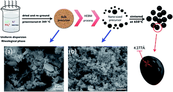
In this work, a high-energy ball mill technique is designed to deal with bulk precursors and achieve particle size minimization. A large amount of the nano-sized precursor is achieved in a narrow particle size distribution of ca. 95 nm. We confirm that the dimensional size of the precursor has a significant influence on the final LiFePO4 particle size and that small grains of the precursor probably form single-crystalline nanoparticles during the calcination process. After carbothermal reduction, the carbon-coated single-crystalline LiFePO4 nanocomposites (nano-CS–LFP) are easily synthesized. Benefiting from the decreasing particle size, the specific surface area of nano-CS–LFP is up to 48.0 m2 g−1, which implies a higher interfacial contact area between the active particles and the electrolyte, as well as an increase in its capacitance capability. Besides, cyclic voltammetry curves of nano-CS–LFP reveal a better capability of reversible reactivity and a lower polarization. Galvanostatic charge–discharge results exhibit excellent rate performance with a discharge capacity of ca. 100 mA h g−1 at 10 °C and a stable cycling property with a capacity retention of ca. 90% after 1000 cycles. In addition, the rapid charge–discharge test over 60 seconds indicates an excellent pulse performance with a high current in a short time period. The combination of the merits of carbon coating and particle size minimization is responsible for the above improvements. Finally, this facile preparation strategy is favorable for the industrial production of economical LiFePO4 materials from lab synthesis.
In this article, similarly to our previous papers,31,33 the precursor is prepared via a rheological phase method in order to guarantee uniform mixing of the raw materials. As for the differences, the extra stage of a high-energy ball mill (HEBM) process is added to deal with the bulk precursor and achieve particle size minimization, while in previous work, very limited attention is paid to optimizing the grain size of the precursor and the bulk particles existing in the precursor are often ignored. The reason for the selection of the HEBM is its advantages of high yield and high efficiency. Namely, compared with a solution chemistry method3 such as the hydrothermal method, the ball mill process is still an economical and simple route without the expensive investment and complicated facilities. Moreover, contrary to the planetary ball mill process, with lower rotation speed, the HEBM process with high rotation speed ensures a high intensity so the bulk precursor is broken into pieces in a short time. With the particle size minimization and subsequent carbothermal reaction process for crystallization, X-ray diffraction (XRD), field-emission scanning electron microscopy (FESEM), high-resolution transmission electron microscopy (HRTEM), and nitrogen sorption are employed to characterize the as-prepared materials. These results show that the carbon-coated single-crystalline LiFePO4 nanocomposites (nano-CS–LFP) are easily synthesized. An electrode composed of nano-CS–LFP exhibits superior physical properties of well-defined crystals and high specific surface area as well as an excellent electrochemical performance, with a high-rate performance and satisfactory capacity retention. Finally, in our view, this synthetic route is easily transferred from lab synthesis to industrial production.
![]() | ||
Scheme 1 Schematic procedures used to prepare nano-CS–LFP composites; embedded SEM images of the bulk precursor of C–LFP (a) and the nano-sized precursor of nano-CS–LFP (b). |
Thermogravimetric (TG) analysis of the two samples was measured from 25 to 850 °C, with a heating rate of 10 °C min−1 under an Ar flow and is shown in Fig. 2. Fig. 2a shows an increasing weight loss with increasing temperature. Because of the decomposition of the pre-sintered product, the weight loss is not as obvious as in Wang's report.33 As for the bulk precursor, the weight loss is caused by further pyrolysis occurring after the pre-sintering temperature (PT). In Fig. 2b, the DSC curve of the bulk precursor shows an obvious exothermic peak at ca. 443 °C, representing crystallization of the LiFePO4 materials.34 However, compared with the bulk precursor, the variation of weight loss at a range of 25–260 °C is more evident, due to the residual ethanol. The weight loss between 260 and 450 °C is also ascribed to the further pyrolysis of the nano-sized precursor, the extent of which is more obvious. Notably, in Fig. 2b an exothermic peak at 439 °C is displayed in the DSC curve of the nano-sized precursor, the crystallization temperature of which is slightly lower than that of the bulk precursor. It is supposed that the decreasing particle size can result in a lower thermal polarization for crystallization. Therefore, the relatively lower temperature for the carbothermal reduction can be adopted to ensure proper kinetics and grain size of the product during the calcination process.35
![]() | ||
Fig. 2 TG (a) and DSC (b) curves of the bulk precursor and nano-sized precursor. PT and ST represent pre-sintering temperature and sintering temperature, respectively. |
Subsequently, XRD measurements were performed to examine the crystal structure of the nano-CS–LFP and C–LFP powders. As shown in Fig. 3, the XRD patterns of nano-CS–LFP and C–LFP were confirmed to be well-crystallized orthorhombic structure LiFePO4 phases, with the space group Pnmb. The lattice parameters were generated: a = 5.9712 Å, b = 10.2198 Å, c = 4.6577 Å for nano-CS–LFP, and a = 5.9923 Å, b = 10.2983 Å, c = 4.6825 Å for C–LFP. Both sets of parameters were very close to the values of the LiFePO4 standard card (ICDD PDF no. 40-1499, a = 6.019 Å, b = 10.347 Å, c = 4.704 Å). Besides, no evidence of diffraction peaks for crystalline carbon appeared in the diffraction patterns of the two samples, indicating that the residual carbon derived from sucrose pyrolysis forms an amorphous phase. As for other physical parameters, the elemental analysis technique and tap density tester were employed to measure the carbon content and tap density of the two samples. According to the results of the carbon content analysis, the residual carbon contents in nano-CS–LFP and C–LFP are 2.74 wt% and 3.18 wt%, respectively. The tap densities of nano-CS–LFP and C–LFP are 1.26 and 1.21 g cm−3, respectively.
The bulk precursor and nano-sized precursor were annealed at 650 °C for 9 h under an Ar atmosphere. SEM was again used to observe the morphology and microstructure of the nano-CS–LFP and C–LFP. After carbothermal reduction for crystallization, the nano-CS–LFP still displayed a nano-sized particle distribution ranging from 40 to 100 nm, as shown in Fig. 4a. The particles at the nanoscale are beneficial in decreasing the distance of the lithium ion transport, leading to a high-rate performance. Therefore, lithium ions can be rapidly extracted from or inserted into the crystal. In addition, the interspaces among the nanoparticles can facilitate the permeation of the electrolyte into the electrode and relieve the volume expansion of particles during the charge–discharge process. Moreover, the uniform distribution of electrolytes in the bulk electrode is beneficial to the rate capability. In contrast, in the bulk precursor, bulk particles are easily formed, as shown in Fig. 4c With increasing magnifications, lots of holes are observed in a broken bulk particle in Fig. 4d, indicating that many closed inner holes exist in the bulk particles. Therefore, the electrolyte sluggishly penetrates into inner holes and lithium ion migration is restricted, probably leading to the partial usage of the active materials. From the comparison of grain size and size distribution of nano-CS–LFP and C–LFP, the evident distinctions illustrate that the particle size distribution of the precursor has a significant effect on the final product. Therefore, the particle size of nano-CS–LFP is tuned via the HEBM process indirectly and effectively. Additionally, the mesopores in the surface of nano-CS–LFP, shown in Fig. 4b, deserve attention. The mesopores mainly originate from the carbothermal process where the pyrolytic carbon reduces the ambient Fe3+ to Fe2+ that has direct contact with the carbon, which releases CO, leaving small pores.36,37
Further information about the unique structure of nano-CS–LFP was obtained by HRTEM. Fig. 5a displays a quasi-spherical particle of about 100 nm with a uniform carbon coating layer of 3 to 5 nm. It is surprising that this whole particle is a single-crystalline structure. Despite the solvothermal synthesis method for LFP-based single-crystalline particles mentioned in previous reports,21–23,38–42 the preparation of a whole particle with single-crystalline structure has rarely been reported via a carbothermal reduction method. The reduction of precursor particle size is beneficial to forming the single-crystalline structure, regarded as a smooth pathway for the transport of lithium ions. Zhu et al.41 reported highly electroactive carbon-coated single-crystalline LiFePO4 nanowires produced by electrospinning. Such short diffusion lengths along the b axis lead to a good rate performance and cycling capability. Secondly, several mesopores of 2 to 8 nm in this particle are observed, which are consistent with the SEM results. It is known that lithium ion extraction/insertion reactions require the transport of electrons and lithium ions simultaneously. We suppose that the mesopores are embedded in the carbon coating layer, which provides channels for rapid Li+ transport without them passing through the conductive carbon layer.11 Such a porous carbon shell promotes the further penetration of electrolytes into the surface of the active particles and thereby is favorable for the electrochemical reaction.43 Thirdly, the uniform carbon coating layers can not only dramatically increase the inter-granular electric conductivity and lithium ion diffusion, but also efficiently hinder particle growth, to lessen the length of lithium ion diffusion within the crystal.
The HRTEM image in Fig. 5b shows the crystal lattice fringes of the nano-CS–LFP with a d-spacing of 0.43 nm, corresponding to the (011) plane of the orthorhombic LiFePO4 crystals. The single-crystalline structure with a high crystallinity is proved by an inset pattern obtained from selected area electron diffraction (SAED). Combined with the observations of the SEM and TEM results, this synthetic methodology can fulfill the following three fundamental requirements4 for active particles to reach an excellent electrochemical performance: (1) the single-crystalline structure supplies a smooth pathway for Li+ transport from or into the crystal that is not blocked;41 (2) particles small enough to lessen the diffusion paths for ion and electron transport; (3) a porous thin shell with a conductive carbon coating ensures that the LiFePO4 particles get electrons from all directions and that ions can penetrate through the conductive coating without appreciable polarization, leading to an acceleration in the rate of lithium ion extraction/insertion from or into the crystal.
The specific surface areas of nano-CS–LFP and C–LFP were analyzed by gas sorption studies and BET theory, as shown in Fig. 6. The isotherms of both composites are type IV and belong to a type H3 hysteresis loop, which typically indicates the existence of mesopores44 originating from the release of gaseous by-products during the calcination process. The specific surface area of nano-CS–LFP is up to 48.0 m2 g−1, which is almost twice that of the C–LFP (24.5 m2 g−1) and even higher than in our previous work.31 Besides, the embedded differential pore volume of nano-CS–LFP concentrates on a single size distribution of mesopores (Fig. 6a), compared with C–LFP which exhibits two types of size distribution (Fig. 6b). To some extent, the higher specific surface area indicates an increasing interfacial contact area between the active materials and the electrolyte, leading to an increase in the reactive sites of the lithium ion extraction/insertion reaction. Therefore, the electrode composed of nano-CS–LFP has the power capability to rapidly respond to the pulse current at a high rate.
![]() | ||
Fig. 6 The nitrogen adsorption/desorption isotherms of nano-CS–LFP (a) and C–LFP (b); the embedded differential pore volume of as-prepared samples. |
The typical charge–discharge profiles of nano-CS–LFP and C–LFP at a current rate of 0.2 C are shown in Fig. 7b. The nano-CS–LFP electrode exhibits a high specific capacity of 160.2 mA h g−1, whereas C–LFP displays a capacity of only 140 mA h g−1. The embedded image in Fig. 7b illustrates the different ΔE values, evaluated from the distance between the charge–discharge operating flat voltages. The values are 42.4 mV and 64.9 mV for nano-CS–LFP and C–LFP, respectively. Due to the same modification with carbon coatings for two samples, such an improvement is attributed to the decrease in particle size in a narrow size distribution, which ensure the shorter transport of lithium ion without excessive polarization.
Subsequently, a comparison of rate performance between nano-CS–LFP and C–LFP, step by step from 0.2 C to 20 C, is presented in Fig. 8a. The electrode composed of nano-CS–LFP exhibits an enhanced electrochemical performance with discharge capacities of about 160.3, 144.8, 117.9, 101.5 and 77.6 mA h g−1 at 0.2 C, 1 C, 5 C, 10 C and 20 C, respectively. Correspondingly, the C–LFP electrode discharges 129.9, 117.2, 94.5, 79.6 and 59.8 mA h g−1. The ratio of discharge capacity increases from 22.9% to 29.8% with an increasing rate. Besides, the discharge capacity can be recovered to its original value as long as the rate is reversed back. Therefore, the enhancements arise from the reduction of particle size, the single-crystalline structure and the conductive porous carbon coating. However, there are still two points worth discussing. For the C–LFP electrode, after performance tests at different rates, the discharge capacity at 0.2 C rate is a little higher than the initial value, which agrees with the SEM results. The electrolyte sluggishly penetrates into the inner holes and the partially active materials are used for Li+ insertion/extraction reaction in the initial test. On the other hand, the improvement in capacity gap for nano-CS–LFP at a high rate is not obvious, which implies that the electronic migration needs further modification with superior conductive materials due to the incomplete graphitization of the sucrose–pyrolytic carbon, leading to the insufficient electronic conductivity.45
![]() | ||
Fig. 8 Rate performances of nano-CS–LFP and C–LFP (a); high-rate cycling performance of nano-CS–LFP (b). |
The high-rate cycling performance of the nano-CS–LFP electrode is shown in Fig. 8b. The nano-CS–LFP electrode exhibits a satisfactory cycling capability with a final discharge capacity of around 100 mA h g−1 and a discharge retention of up to 90% over 1000 cycles at 10 C rate. According to the rate and cycling test results, the well-defined crystal structure and intimate adhesion in the bulk electrode is not destroyed due to the high-rate cycles, which can meet the stringent requirements of EVs and HEVs for practical applications.
In order to simulate the practical acceleration of the starting and recovering brake-energy of EVs and HEVs, an electrochemical test is carried out with a protocol of 60 seconds for each of the rapid charge–discharge processes.46 Fig. 9 shows the terminal charge–discharge voltages of nano-CS–LFP at 10 C rate. Over 300 cycles, both smooth curves represent an outstanding cycling stability. The embedded charge or discharge profile shows a stable operating flat voltage under a high current for one minute, which is beneficial for the stability of the whole battery system, including hundreds of single batteries. Moreover, the electrode exhibits a better power performance with the cycling number. Therefore, such good pulse performance implies a potential capability to meet the demands of continuous go-and-stop in urban traffic congestion.
![]() | ||
Fig. 9 The rapid charge–discharge test for nano-CS–LFP at 10 C rate; the embedded variation of the operating voltage in the rapid charge–discharge test. |
In summary, the above pre-eminent rate performance of nano-CS–LFP can be explained from two aspects. Namely, its merits are the carbon coating and the particle size minimization, which play important but different roles in improving the electrochemical performance of LFP-based composites. In situ carbon coating enhances the electronic conductivity. Besides, with the help of the carbon coating in restricting the crystal growth and suppressing agglomeration, the nano-sized precursor has much more of a chance to form single-crystalline particles during the calcination process. In turn, the particle size minimization decreases the lengths of the ion and electron transport. Additionally, a higher specific surface area is achieved with decreasing particle size. Both the above merits are combined in a kind of synergy effect to enhance the power performance. Besides, it is a most economical strategy for producing LFP-based composites.
This journal is © The Royal Society of Chemistry 2014 |