DOI:
10.1039/C3RA46971A
(Paper)
RSC Adv., 2014,
4, 12756-12762
Ship in a bottle synthesis of ionic liquids in NaY supercages for CO2 capture
Received
23rd November 2013
, Accepted 26th February 2014
First published on 26th February 2014
Abstract
CO2 is the single most important anthropogenic greenhouse gas, contributing ∼64% to the global radiative forcing. And the rising concentration of CO2 in the atmosphere will result in global climate change. In this study, 1-alkyl-3-methylimidazolium bromide ionic liquids (ILs) ([CnMIM]Br, n = 4, 6, 8, 10) were ship in a bottle synthesized in NaY zeolite to get [CnMIM]Br@NaY samples and applied for CO2 capture. These samples were then characterized by elemental analysis, thermal gravimetric analysis (TGA), X-ray diffraction (XRD) and FT-Raman spectra. The results indicated that [CnMIM]Br ILs were successfully encapsulated inside NaY and the encapsulated [CnMIM]Br ILs were much more stable than their bulk analogues. And Raman spectra showed that the relative intensities of some peaks in the [CnMIM]Br@NaY samples had good relationships with the side chain length of ILs. Then the breakthrough curves were recorded to evaluate the CO2 adsorption capacity of these samples, and indicated that the highest adsorption capacity could reach up to 20.08 mL CO2 per g [C4MIM]Br@NaY. And the cyclic CO2 adsorption results also illustrated that the [CnMIM]Br@NaY samples were stable and effective with prolonged use. So these samples could be potential materials for CO2 capture.
1. Introduction
It is reported that CO2 in the atmosphere has increased to about 390 ppm and CO2 is the single most important anthropogenic greenhouse gas, contributing ∼64% to the global radiative forcing.1,2 The increasing concentration of CO2 is widely regarded as a key factor in global climate change.3,4 Therefore, significant investments have been made to capture CO2 in low-cost, high-efficiency ways. Due to their unique physicochemical properties,5,6 ionic liquids (ILs) were attracting more and more attention in the field of CO2 capture. Welton found that there was high solubility of CO2 in imidazolium ILs ([C4MIM]BF4, [C4MIM]PF6) due to a weak Lewis acid–base interaction between CO2 and ILs.7 Brennecke also found that CO2 was remarkably soluble in alkylimidazolium ILs ([C2MIM]EtSO4, [C4MIM]NO3, [C4MIM]PF6, [C8MIM]BF4, [C8MIM]PF6).8 Recently they reported two amino acid functionalized ILs reacted with CO2 in a molar ratio of 1![[thin space (1/6-em)]](https://www.rsc.org/images/entities/char_2009.gif) :1.9 Although ILs have shown great potential on CO2 capture in laboratory scale, it is worth noting that there are not yet any known large-scale industrial application of ILs in CO2 capture. This phenomenon is attributed to the limitations of bulk ILs, including high cost of large amount of ILs, difficulty in mass or heat transfer caused by high viscosity and low specific surface of bulk ILs systems.10 ILs were introduced onto some porous supports to produce supported ionic liquids membranes (SILMs)11 to eliminate these limitations, however, SILMs could only be operated at low differential pressures to avoid blowing ILs out of the pores in the support.12 To optimize the operational parameters such as stability and longevity13 of these membranes, a series of excellent and systematic works had been done by Gin and Noble et al., imidazolium based ILs containing oligo(ethylene glycol) or nitrile functional groups were synthesized as monomers, then tethered to the polystyrene, polyacrylate or polyvinyl backbone to obtain poly(RTIL) membranes and applied for CO2 capture.14–19 An undesirable outcome of the enhanced stability of the RTIL-based membranes was a substantial decrease in gas diffusivity and permeability, CO2 permeability was found to be several orders of magnitude lower than analogous RTILs.19 It is noted that zeolites have been widely used in gas adsorption and separation because of their advantages such as large specific surface area, chemical and thermal stability, high adsorption capacity, and moderate costs.20 E.g. ZSM-5 was incorporated into a polydimethylsiloxane (PDMS) matrix to prepare mixed-matrix membranes (MMMs), separating CO2 from gas mixtures. These membranes could be used up to 250 °C and CO2 loading was found to be increased as compared to the pure polymer membrane.21
:1.9 Although ILs have shown great potential on CO2 capture in laboratory scale, it is worth noting that there are not yet any known large-scale industrial application of ILs in CO2 capture. This phenomenon is attributed to the limitations of bulk ILs, including high cost of large amount of ILs, difficulty in mass or heat transfer caused by high viscosity and low specific surface of bulk ILs systems.10 ILs were introduced onto some porous supports to produce supported ionic liquids membranes (SILMs)11 to eliminate these limitations, however, SILMs could only be operated at low differential pressures to avoid blowing ILs out of the pores in the support.12 To optimize the operational parameters such as stability and longevity13 of these membranes, a series of excellent and systematic works had been done by Gin and Noble et al., imidazolium based ILs containing oligo(ethylene glycol) or nitrile functional groups were synthesized as monomers, then tethered to the polystyrene, polyacrylate or polyvinyl backbone to obtain poly(RTIL) membranes and applied for CO2 capture.14–19 An undesirable outcome of the enhanced stability of the RTIL-based membranes was a substantial decrease in gas diffusivity and permeability, CO2 permeability was found to be several orders of magnitude lower than analogous RTILs.19 It is noted that zeolites have been widely used in gas adsorption and separation because of their advantages such as large specific surface area, chemical and thermal stability, high adsorption capacity, and moderate costs.20 E.g. ZSM-5 was incorporated into a polydimethylsiloxane (PDMS) matrix to prepare mixed-matrix membranes (MMMs), separating CO2 from gas mixtures. These membranes could be used up to 250 °C and CO2 loading was found to be increased as compared to the pure polymer membrane.21
In this study, we would like to create one kind of composite materials for CO2 capture, which can solve the limitations of bulk ILs and combine the advantages of ILs and zeolites. Therefore, a series of imidazolium ILs ([CnMIM]Br, n = 4, 6, 8, 10) were synthesized in NaY zeolite by ship in a bottle strategy22,23 to get the [CnMIM]Br@NaY samples. The obtained samples were then characterized by TGA, XRD and FT-Raman. The results showed that the [CnMIM]Br ILs were successfully immobilized inside the supercages of NaY, and the onset decomposition temperatures of the encapsulated [CnMIM]Br ILs were as high as ∼370 °C, which were much higher than the onset decomposition temperatures of the bulk [CnMIM]Br ILs (∼250 °C). It meant that the encapsulated ILs were much more stable than the bulk ones. The CO2 adsorption capacities of these samples were also investigated, the results showed that the highest adsorption capacity could reach up to 20.08 mL CO2 per g [C4MIM]Br@NaY. So these samples could combine the advantages of ILs and NaY zeolite and be applied for CO2 capture efficiently.
2. Experimental section
2.1 Materials
NaY zeolite was purchased from Nankai University catalyst Co., Ltd., and calcined at 600 °C in air for 4 h before use. N-Methylimidazole (MIM), and 1-bromobutane (n-C4H9Br), 1-bromohexane (n-C6H13Br), 1-bromooctane (n-C8H17Br), 1-bromodecane (n-C10H21Br) were all analytical reagents and purchased from Guanghua Sci. Tech. Co., Ltd. He (99.999%) and 14.9% CO2 (in He balance, v/v) were obtained from Guangzhou Zhuozheng gas Co., Ltd.
2.2 Ship in a bottle synthesis
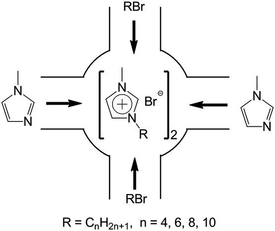
The schematic illustration of ship in a bottle synthesis of the [CnMIM]Br@NaY samples are shown in Fig. 1. The detailed preparation procedures of the [CnMIM]Br@NaY samples were described as follows (taken [C4MIM]Br@NaY as an example): 3.00 g NaY (∼2 mmol of supercages) and 7.40 g N-methyl-imidazole (90 mmol) were added to a 100 mL flask and stirred at room temperature for 15 h. Then 13.60 g 1-bromobutane (n-C4H9Br, 0.10 mmol) was added and stirred for 24 h. After that, the mixture was filtered and Soxhlet extracted by ethanol at 70 °C for 24 h to remove unreacted reagents and non-encapsulated (just adsorbed on the surface of NaY zeolite) [C4MIM]Br. Finally, the solid was dried at 80 °C in vacuum for 24 h to get [C4MIM]Br@NaY.
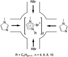 |
| | Fig. 1 Illustration of ship in a bottle synthesis of [CnMIM]Br@NaY. | |
2.3 Characterization and CO2 adsorption studies
TGA was carried on a STA 449C (Netzsch) in N2 atmosphere from 50 to 550 °C at a heating rate of 10 °C min−1. XRD patterns were obtained on a Bruker D-8 ADVANCE diffractometer using a CuKα-ray source (40 kV, 40 mA) with scanning step 0.02° between 5° and 45°. FT-Raman was carried out over a LabRamHR (Horiba Jobin Yvoc Inc.), and all the experiments were carried out using the excitation line of 632.8 nm from an internal He–Ne laser with a power of 6 mW on the electrode surface. CO2 adsorption studies were carried out using breakthrough curves in packed columns on 0.1 g scale. The adsorbent was firstly treated at 200 °C for 30 min with He gas at the flow rate of 30 mL min−1. It was then cooled to the desired adsorption temperature (35–65 °C, in 10 °C increments), which covers the typical temperature range of flue gas. The flow of gas was then changed to 14.9 vol% CO2 in He balance at the flow rate of 30 mL min−1. The adsorption was continued until saturation was achieved and the breakthrough curves were recorded. The stability of [CnMIM]Br@NaY samples during the prolonged cyclic CO2 adsorption was investigated for 6 cycles of adsorption and regeneration with [C10MIM]Br@NaY as representative adsorbent. CO2 adsorption was performed at 65 °C, while the regeneration was conducted with the flush of He gas at 200 °C for 30 min.
3. Results and discussion
3.1 Elemental analysis
In this study, extensive Soxhlet extraction was taken after the synthesis of all the [CnMIM]Br@NaY samples. So all un-reacted reagents and non-encapsulated ILs can be removed, while the encapsulated ILs, which are too bulky to diffuse through the internal pores, will remain inside the supercages. Thus elemental analysis can exactly evaluate the loadings of encapsulated ILs and their molar ratio to the supercages (SCs). The results are shown in Table 1. It can be seen that the loadings of [CnMIM]Br are 18.5, 22.5, 17.6, 11.4% for n = 4, 6, 8, 10, respectively. And the corresponding molar ratio of ILs to SCs (ILs/SCs) are 1.6, 1.8, 1.2, and 0.7. Both the ILs loadings and ILs/SCs firstly increase and then decrease with the increasing side chain length (the increasing number of n). Although the molar ratio of starting reagents (N-methylimidazole) to SCs is as high as ∼45, the resulting ILs/SCs are all less than 2. It means that each supercage of NaY can hold no more than 2 IL molecules, which is determined by the sizes of [CnMIM]Br ILs24 and the diameter of the supercages in NaY (11.8 Å).25
Table 1 Elemental analysis of NaY, [CnMIM]Br@NaY (n = 4, 6, 8, 10)
| Samples |
C (%) |
H (%) |
N (%) |
ILs loading (%) |
ILs/SCs |
| NaY |
0.02 |
2.95 |
0.25 |
— |
— |
| [C4MIM]Br@NaY |
8.12 |
1.91 |
3.11 |
18.5 |
1.6 |
| [C6MIM]Br@NaY |
10.95 |
1.86 |
3.83 |
22.5 |
1.8 |
| [C8MIM]Br@NaY |
9.26 |
1.71 |
2.88 |
17.6 |
1.2 |
| [C10MIM]Br@NaY |
6.31 |
2.87 |
1.65 |
11.4 |
0.7 |
3.2 Thermogravimetric analysis
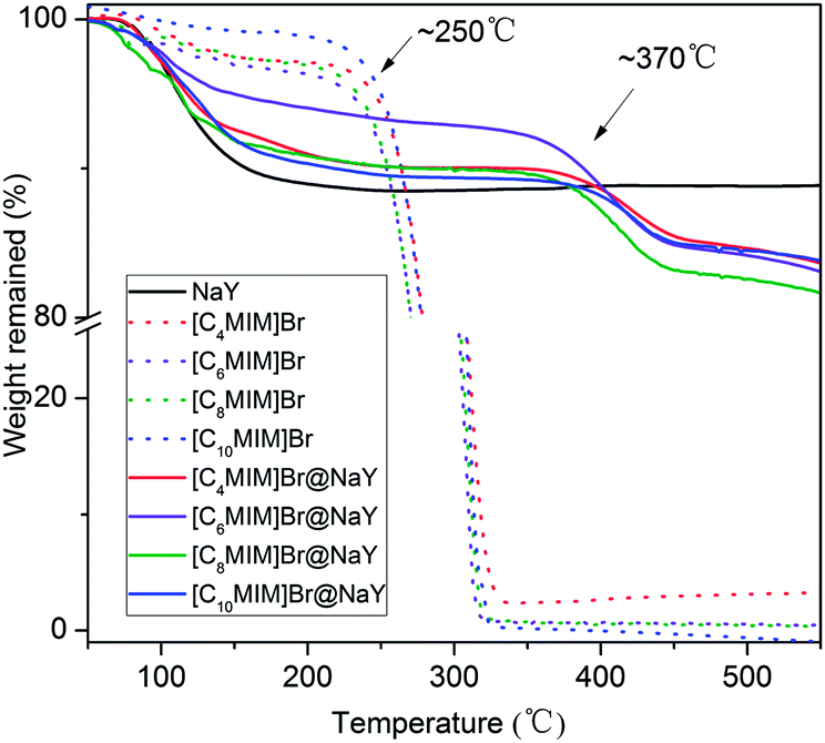
In order to investigate the thermo stability of the obtained [CnMIM]Br@NaY (n = 4, 6, 8, 10) samples, thermogravimetric analyses were performed and as comparisons, the thermo stability of the samples of NaY, [CnMIM]Br (n = 4, 6, 8, 10) were also studied. And all the TGA profiles are shown in Fig. 2. It can be seen from Fig. 2 that there are small amounts of weight losses in all the samples before the temperatures of decomposition. For example, the weight losses of [CnMIM]Br before 120 °C are 1.65% (n = 4), 2.53% (n = 6), 2.15% (n = 8) and 1.45% (n = 10), which can be attributed to the loss of trace water in bulk ILs. While the weight losses of [CnMIM]Br@NaY before 120 °C are 5.28% (n = 4), 3.78% (n = 6), 6.25% (n = 8), 4.93% (n = 10), which belong to the loss of lattice water in the zeolite26 or the [CnMIM]Br@NaY samples (the weight loss of NaY before 120 °C is 6.39%). Fig. 2 also shows that all the [CnMIM]Br ILs start to decompose at ∼250 °C (essentially consistent with the results reported in the literature27), then the significant weight losses are observed due to the decomposition of ILs. As for the samples of [CnMIM]Br@NaY, the onset decomposition temperatures are as high as ∼370 °C. It means that the encapsulated ILs are much more stable than the bulk ones, which can be attributed to the porous nature of the [CnMIM]Br@NaY samples.
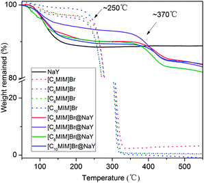 |
| | Fig. 2 TGA of NaY, [CnMIM]Br and [CnMIM]Br@NaY (n = 4, 6, 8, 10). | |
3.3 XRD analysis
The recorded XRD patterns of NaY and all the [CnMIM]Br@NaY samples are presented in Fig. 3. The characteristic peaks of NaY28 are clearly present in the spectra of all samples, indicating that the encapsulation procedure do not destroy NaY zeolite framework. And it can be seen from Fig. 3 that the relationships between I220 (the intensity of [2 2 0] reflection) and I311 (the intensity of [3 1 1] reflection) are totally different in NaY and [CnMIM]Br@NaY. In NaY, I220 > I311; while in the [CnMIM]Br@NaY samples, I220 < I311. Similar observations have been reported on the encapsulation of FeII(bpy)3,29 polypyrrole (PPy)30 and [HMIM][TFSI] ILs31 into the supercages of NaY. These phenomena have been attributed that Na+ ions are redistributed from their random positions in NaY supercages to locations at specific sites by the incorporation of large ions (FeII(bpy)3, PPy, [HMIM]+ and [CnMIM]+). Further, these phenomena can also provide strong support for the incorporation of large compounds ([CnMIM]Br in this study) into NaY zeolite.30,31
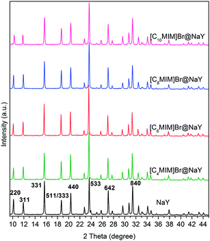 |
| | Fig. 3 XRD spectra of NaY and [CnMIM]Br@NaY (n = 4, 6, 8, 10). | |
3.4 FT-Raman spectroscopy
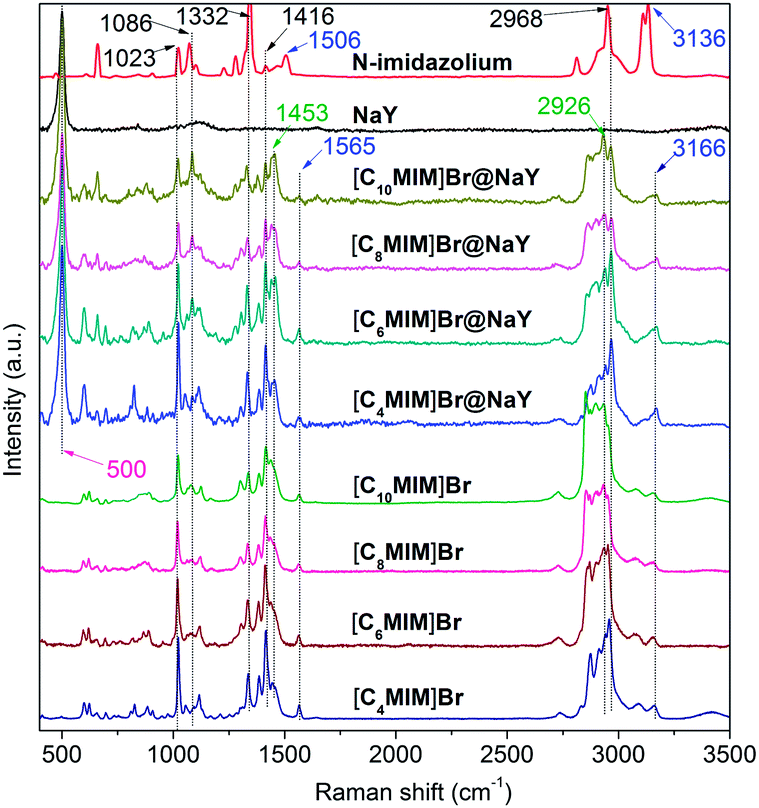
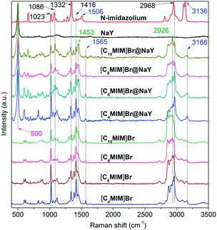
FT-Raman spectra of N-methylimidazole (MIM), NaY, [CnMIM]Br and [CnMIM]Br@NaY (n = 4, 6, 8, 10) are shown in Fig. 4. Characteristic bands and their corresponding assignments are listed in Table 2.
 |
| | Fig. 4 FT-Raman spectra of MIM, NaY, [CnMIM]Br and [CnMIM]Br@NaY (n = 4, 6, 8, 10). | |
Table 2 Raman bands and their corresponding assignments
| Bands (cm−1) |
Assignments |
| 500 |
Framework T–O vibration in the zeolite32 |
| 1023 |
CH3 bending and ring bending (in-plane)33,34 |
| 1086 |
C–H bending and ring stretching33 |
| 1332 |
Ring stretching and CH3 bending33,34 |
| 1416 |
CH3 symmetrical bending33,34 |
| 1453 |
CH2 deformation in the side chain35 |
| 1565 |
N–CH3 stretching and ring stretching34,36 |
| 2926 |
CH2 stretching in the side chain35 |
| 2968 |
CH3 symmetrical stretching35 |
| 3166 |
C–H stretching in the ring33,35 |
It can be seen from Fig. 4 that NaY has only a sharp peak at 500 cm−1, which can also be found in all the [CnMIM]Br@NaY samples. The Raman spectroscopy of N-methylimidazole is well consistent with the reported results.34 The bands of 1023, 1086, 1332, 1416 and 2968 cm−1 can be found in N-methylimidazole, [CnMIM]Br and [CnMIM]Br@NaY; but bands of 1506 (N–CH3 stretching and ring stretching), 3136 cm−1 (C–H stretching in the ring) in N-methylimidazole shift to higher wavenumbers of 1565 and 3166 cm−1 in [CnMIM]Br and [CnMIM]Br@NaY. These blue shifts can be explained by the formation of hydrogen bonding37 between H in the imidazolium ring and Br− in [CnMIM]Br ILs, and/or the basic sites in NaY zeolite. Compared with the Raman spectroscopy of N-methylimidazole, there are two new bands of 1453 and 2926 cm−1 in the [CnMIM]Br and [CnMIM]Br@NaY samples, which can be attributed to the introduction of the side chains (–CH2 groups) onto the imidazolium rings.35
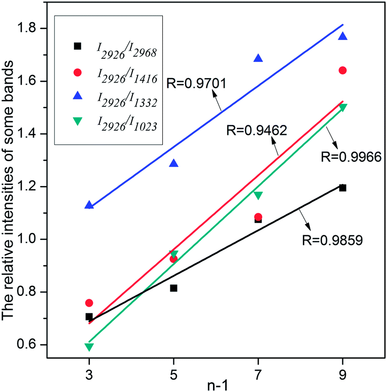
In all the [CnMIM]Br@NaY samples, the characteristic peak positions of [CnMIM]Br do not vary with the length of the side chain, thus confirming their similar molecular orientation and conformation in the NaY zeolite.38 Although the peak positions do not change with the side chain length, but the relative intensities of these bands do change. In some studies, the relative intensities of Raman peaks had already successfully been used to determine important physical structure of some samples in a wide range of types, including the chain length.39,40 Smith et al. found the raman spectra of oligomeric glycines had band in 1665 cm−1 sensitive to the length of the polyglycine, the intensity decreased with the increase of the chain length.41 In the Raman spectra of t-butyl-capped polyenes, the non-resonant intensities in the regions of 1500–1600 cm−1 and 1100–1200 cm−1 showed a super-linear increase with the length of the polyene chain.42 And Levin et al. found that bulk Raman spectra of liquid alkanethiols in the 200–300 cm−1 range clearly exhibited the dependence on carbon-chain-length.43 In this study, it can also be seen from Fig. 4 that the characteristic bands intensities of [CnMIM]Br@NaY are regularly changed with the side chain length. The intensities of bands on 1023, 1332, 1416 and 2968 cm−1 are found to decrease with the increase of the side chain length. On the contrary, the peak intensities of 1453 and 2926 cm−1 increase with the increasing numbers of –CH2 groups (n − 1) in the side chain of [CnMIM]Br@NaY. In order to eliminate the effects of different ILs loadings in NaY zeolite, the relative intensities of 2926 cm−1 to 2968, 1416, 1332 and 1023 cm−1 (I2926/I2968,1416,1332,1023) are plotted against –CH2 group numbers (n − 1) in the samples of [CnMIM]Br@NaY and shown in Fig. 5. It is interesting to see that there are good linear relations between I2926/I2968,1416,1332,1023 and n − 1 with correlation coefficients of 0.9859, 0.9462, 0.9701, and 0.9966 respectively. Hence, this will be another proof of successful encapsulation of [CnMIM]Br in NaY zeolite for the reason that all unreacted reagents (n-CnH2n+1Br) and non-encapsulated [CnMIM]Br ILs can be removed from [CnMIM]Br-@NaY samples through extensive Soxhlet extraction.
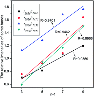 |
| | Fig. 5 The relative intensities of some bands against –CH2 number (n − 1) in the side chain of [CnMIM]Br. | |
3.5 CO2 adsorption study
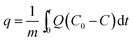
CO2 adsorption studies of the [CnMIM]Br@NaY samples were operated as described in Experimental section. The CO2 adsorption capacity (q, mL g−1) of the [CnMIM]Br@NaY samples at a certain time (t, s) was calculated as expressed in eqn (1) (ref. 44)| |
 | (1) |
where m is the dry weight of the adsorbents (g), Q is the influent flow rate (mL s−1), C0 and C are the influent and effluent CO2 concentration (vol%). The breakthrough curves of the [CnMIM]Br@NaY samples are shown in Fig. 6. And the CO2 adsorption capacities of the corresponding samples at the different temperature can be found in Table 3.
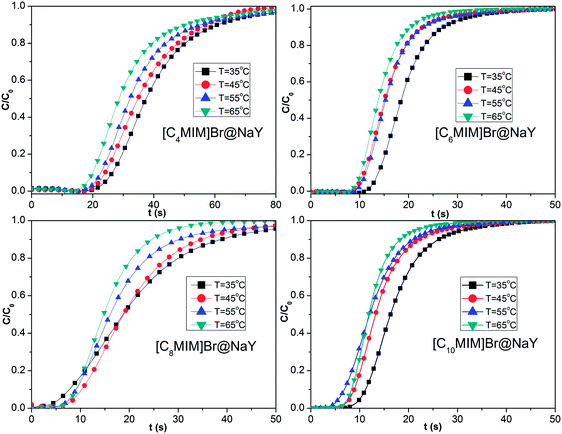 |
| | Fig. 6 The breakthrough curves of the samples of [CnMIM]Br@NaY (n = 4, 6, 8, 10) at different temperature of 35, 45, 55, 65 °C. | |
Table 3 The CO2 adsorption capacity (q, mL g−1) of the samples at the different temperatures
| Samples |
35 °C |
45 °C |
55 °C |
65 °C |
| [C4MIM]Br@NaY |
20.08 |
16.02 |
14.76 |
14.25 |
| [C6MIM]Br@NaY |
17.61 |
15.75 |
12.19 |
11.85 |
| [C8MIM]Br@NaY |
16.60 |
13.96 |
12.42 |
10.69 |
| [C10MIM]Br@NaY |
14.22 |
12.02 |
11.02 |
10.08 |
From Fig. 6 and Table 3, it can be seen that both the saturation time (tsat, defined as the time, at which C/C0 = 0.9) and the CO2 adsorption capacity (q) of the same sample drop continuously with the increasing temperature. Taken [C4MIM]Br@NaY as an example, tsat is found to be decreased from 60.72 s (35 °C), 56.82 s (45 °C), 55.76 s (55 °C) to 50.89 s (65 °C); meanwhile, q is reduced from 20.08 (35 °C), 16.02 (45 °C), 14.76 (55 °C) to 14.25 mL g−1 (65 °C). These phenomena can be attributed that the increase of temperature leads to the decrease of van der Waals' force between CO2 molecule and the surface of the samples. From Table 3, it can also be seen that the CO2 adsorption capacities (q) of different samples at the same temperature are decreased with the increase of the side chain length of these [CnMIM]Br@NaY samples, although the loading of [C4MIM]Br is slightly less than its [C6MIM]Br analogue in their corresponding samples of [CnMIM]Br@NaY. It is reported that the charge balance cation (in this study, that means [CnMIM]+) can play an important role in CO2 adsorption. Because different cations have different polarizing power, they can affect the effective window size and pore volume of the zeolites, they can also affect the strength of the local electric fields and the basicity of the zeolites.20 With the increase of the side chain length, the ionic radius of those cations will be increased, the polarizing power and the interaction with CO2 will be weakened; the surface area and pore volume of the corresponding samples will be reduced, and finally the CO2 adsorption capacity will be decreased.
CO2 adsorption capacity of [C4MIM]Br@NaY samples at 35 °C is 20.08 mL g−1, it is equal to 0.80 mmol CO2 per g samples (∼0.04 g CO2 per g) based on ideal gas law equation, which is close to the results reported by König et al.21 In their study, MMMs were obtained with CO2 adsorption capacity reaching up to about 0.05 and 0.06 g CO2 per g membrane, as the content of ZSM-5 in PDMS was 38% and 56%, respectively. The loading of [C4MIM]Br is 18.5% according to the elemental analysis results in Table 1, that's to say that there is 0.185 g (0.84 mmol) [C4MIM]Br in per gram of [C4MIM]Br@NaY samples. So the molar ratio of adsorbed CO2 to encapsulated [C4MIM]Br IL in 1 g of [C4MIM]Br@NaY is nearly 1:1 (0.80/0.84), almost same as the results obtained by the two amino acid functionalized ILs,9 and twice of the stoichiometric ratio of CO2 to monoethanolamine (MEA) and diethanolamine (DEA), two most commonly used CO2 absorbents in the large scale industrial applications.45
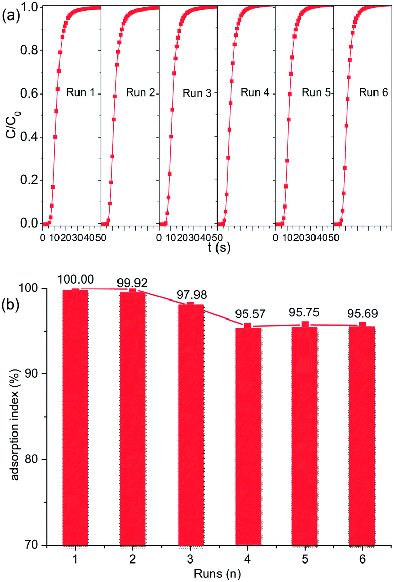
3.6 Prolonged cyclic CO2 adsorption
The prolonged cyclic CO2 adsorption on [C10MIM]Br@NaY was conducted as mentioned in the Experimental section, and the results are shown in Fig. 7. The percentage ratio of the adsorption capacity of the regenerated adsorbent to the virgin one is defined as adsorption index. It can be seen from Fig. 7 that the adsorption index is only reduced from 100% to 95.69% at the sixth run, suggesting that most CO2 molecules can be effectively desorbed during the regeneration procedure, and the [CnMIM]Br@NaY samples in the present study are satisfactorily stable and effective in the prolonged cyclic operation. The long term stability of the [CnMIM]Br@NaY samples can be attributed to the excellent physicochemical characteristics of ILs, especially to their good thermal stability and nonvolatility. While CO2 adsorption capacity of DEA-modified MCM-41 was decreased from 100% to 83.2% after 5 cycles at a moderate regeneration temperature of 60 °C because of amine degradation and evaporative losses under the desorption condition.46
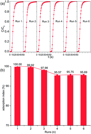 |
| | Fig. 7 Prolonged cyclic CO2 adsorption performance of [C10MIM]Br-@NaY. (a) Breakthrough curves and (b) adsorption index of six runs (n). | |
4. Conclusions
[CnMIM]Br ILs were successfully encapsulated in the supercages of NaY zeolite to obtain the [CnMIM]Br@NaY samples by ship in a bottle strategy. The encapsulated [CnMIM]Br ILs are much more stable than the bulk ones. CO2 adsorption studies showed that these samples could probably solve the limitations of bulk ILs (high cost and difficulty in mass or heat transfer) and combine the advantages of ILs and NaY zeolite. Then these samples could be potential materials for CO2 capture in the near future.
Acknowledgements
We gratefully acknowledge the financial support of the National Natural Science Foundation of China (Grant no. 21006035, 21176088) and Natural Science Foundation of Guangdong (Grant no. s2011020001472).
Notes and references
- WMO Greenhouse Gas Bulletin No. 8, World Meteorological Organization, Geneva, Switzerland, 2012, http://www.wmo.int/pages/prog/arep/gaw/ghg/GHGbulletin.html.
- S. D. Kenarsari, D. L. Yang, G. D. Jiang, S. J. Zhang, J. J. Wang, A. G. Russell, Q. Wei and M. H. Fan, RSC Adv., 2013, 3, 22739–22773 RSC.
- C. M. Wang, X. Y. Luo, X. Zhu, G. K. Cui, D. Jiang, D. S. Deng, H. R. Li and S. Dai, RSC Adv., 2013, 3, 15518–15527 RSC.
- S. H. Ren, Y. C. Hou, W. Z. Wu, S. D. Tian and W. N. Liu, RSC Adv., 2012, 2, 2504–2507 RSC.
- P. C. Hillesheim, J. A. Singh, S. M. Mahurin, P. F. Fulvio, Y. Oyola, X. Zhu, D. Jiang and S. Dai, RSC Adv., 2013, 3, 3981–3989 RSC.
- Y. Cao, X. Sun, Y. Chen and T. Mu, ACS Sustainable Chem. Eng., 2013, 2, 138–148 CrossRef.
- S. G. Kazarian, B. J. Briscoe and T. Welton, Chem. Commun., 2000, 2047–2048 RSC.
- L. A. Blanchard, Z. Gu and J. F. Brennecke, J. Phys. Chem. B, 2001, 105, 2437–2444 CrossRef CAS.
- B. E. Gurkan, J. C. de la Fuente, E. M. Mindrup, L. E. Ficke, B. F. Goodrich, E. A. Price, W. F. Schneider and J. F. Brennecke, J. Am. Chem. Soc., 2010, 132, 2116–2117 CrossRef CAS PubMed.
- Y. L. Gu and G. X. Li, Adv. Synth. Catal., 2009, 351, 817–847 CrossRef CAS.
- P. Scovazzo, J. Kieft, D. A. Finan, C. Koval, D. DuBois and R. Noble, J. Membr. Sci., 2004, 238, 57–63 CrossRef CAS PubMed.
- B. A. Voss, J. E. Bara, D. L. Gin and R. D. Noble, Chem. Mater., 2009, 21, 3027–3029 CrossRef CAS.
- D. L. Gin and R. D. Noble, Science, 2011, 332, 674–676 CrossRef CAS PubMed.
- J. E. Bara, C. J. Gabriel, S. Lessmann, T. K. Carlisle, A. Finotello, D. L. Gin and R. D. Noble, Ind. Eng. Chem. Res., 2007, 46, 5380–5386 CrossRef CAS.
- J. E. Bara, S. Lessmann, C. J. Gabriel, E. S. Hatakeyama, R. D. Noble and D. L. Gin, Ind. Eng. Chem. Res., 2007, 46, 5397–5404 CrossRef CAS.
- T. K. Carlisle, J. E. Bara, C. J. Gabriel, R. D. Noble and D. L. Gin, Ind. Eng. Chem. Res., 2008, 47, 7005–7012 CrossRef CAS.
- J. E. Bara, C. J. Gabriel, E. S. Hatakeyama, T. K. Carlisle, S. Lessmann, R. D. Noble and D. L. Gin, J. Membr. Sci., 2008, 321, 3–7 CrossRef CAS PubMed.
- J. E. Bara, D. E. Camper, D. L. Gin and R. D. Noble, Acc. Chem. Res., 2009, 43, 152–159 CrossRef PubMed.
- T. K. Carlisle, E. F. Wiesenauer, G. D. Nicodemus, D. L. Gin and R. D. Noble, Ind. Eng. Chem. Res., 2012, 52, 1023–1032 CrossRef.
- Q. L. Liu, T. Pham, M. D. Porosoff and R. F. Lobo, ChemSusChem, 2012, 5, 2237–2242 CrossRef CAS PubMed.
- M. Hussain and A. König, Chem. Eng. Technol., 2012, 35, 561–569 CrossRef CAS.
- Y. Tanamura, T. Uchida, N. Teramae, M. Kikuchi, K. Kusaba and Y. Onodera, Nano Lett., 2001, 1, 387–390 CrossRef CAS.
- A. M. López-Periago, C. A. García-González, J. Saurina and C. Domingo, Microporous Mesoporous Mater., 2010, 132, 357–362 CrossRef PubMed.
- B. L. Bhargava and M. L. Klein, J. Phys. Chem. A, 2008, 113, 1898–1904 CrossRef PubMed.
- A. J. Fowkes, R. M. Ibberson and M. J. Rosseinsky, Chem. Mater., 2002, 14, 590–602 CrossRef CAS.
- N. Nunes, R. Amaro, F. Costa, E. Rombi, M. A. Carvalho, I. C. Neves and A. M. Fonseca, Eur. J. Inorg. Chem., 2007, 1682–1689 CrossRef CAS.
- C. P. Fredlake, J. M. Crosthwaite, D. G. Hert, S. N. V. K. Aki and J. F. Brennecke, J. Chem. Eng. Data, 2004, 49, 954–964 CrossRef CAS.
- K. Tang, Y. G. Wang, L. J. Song, L. H. Duan, X. T. Zhang and Z. L. Sun, Mater. Lett., 2006, 60, 2158–2160 CrossRef CAS PubMed.
- W. H. Quayle and J. H. Lunsford, Inorg. Chem., 1982, 21, 97–103 CrossRef CAS.
- M. Nakayama, J. Yano, K. Nakaoka and K. Ogura, Synth. Met., 2003, 138, 419–422 CrossRef CAS.
- S. Ntais, A. M. Moschovi, F. Paloukis, S. Neophytides, V. N. Burganos, V. Dracopoulos and V. Nikolakis, J. Power Sources, 2011, 196, 2202–2210 CrossRef CAS PubMed.
- A. Corma and H. Garcia, Eur. J. Inorg. Chem., 2004, 1143–1164 CrossRef CAS.
- D. A. Carter and J. E. Pemberton, J. Raman Spectrosc., 1997, 28, 939–946 CrossRef CAS.
- Y. X. Yuan, T. C. Niu, M. M. Xu, J. L. Yao and R. A. Gu, J. Raman Spectrosc., 2010, 41, 516–523 CrossRef CAS.
- R. W. Berg, M. Deetlefs, K. R. Seddon, I. Shim and J. M. Thompson, J. Phys. Chem. B, 2005, 109, 19018–19025 CrossRef CAS PubMed.
- F. Shi and Y. Q. Deng, Spectrochim. Acta, Part A, 2005, 62, 239–244 CrossRef PubMed.
- P. D. Vaz and P. J. A. Ribeiro-Claro, J. Raman Spectrosc., 2003, 34, 863–867 CrossRef CAS.
- A. Baptiste, A. Gibaud, J. F. Bardeau, K. Wen, R. Maoz, J. Sagiv and B. M. Ocko, Langmuir, 2002, 18, 3916–3922 CrossRef CAS.
- J. R. Beattie, S. J. Bell and B. Moss, Lipids, 2004, 39, 407–419 CrossRef CAS.
- P. Colomban and A. Slodczyk, Opt. Mater., 2009, 31, 1759–1763 CrossRef CAS PubMed.
- M. Smith, A. G. Walton and J. L. Koenig, Biopolymers, 1969, 8, 29–43 CrossRef CAS.
- C. Castiglioni, M. Tommasini and G. Zerbi, Philos. Trans. R. Soc. London, Ser. A, 2004, 362, 2425–2459 CrossRef CAS PubMed.
- C. S. Levin, B. G. Janesko, R. Bardhan, G. E. Scuseria, J. D. Hartgerink and N. J. Halas, Nano Lett., 2006, 6, 2617–2621 CrossRef CAS PubMed.
- C. S. Lu, H. L. Bai, B. L. Wu, F. S. Su and J. F. Hwang, Energy Fuels, 2008, 22, 3050–3056 CrossRef CAS.
- E. B. Rinker, S. S. Ashour and O. C. Sandall, Ind. Eng. Chem. Res., 2000, 39, 4346–4356 CrossRef CAS.
- A. Sayari, WO Pat., Appl., 2004 054708 A2, 2004.
|
| This journal is © The Royal Society of Chemistry 2014 |
Click here to see how this site uses Cookies. View our privacy policy here.