DOI:
10.1039/C3RA46881J
(Communication)
RSC Adv., 2014,
4, 7511-7515
Enhancement and wettability of self-assembled GO sheets as interfacial layers of CF/PI composites
Received
20th November 2013
, Accepted 7th January 2014
First published on 9th January 2014
Abstract
The self-assembled GO interlayers are easily fabricated by a dip coating process. Carbon fiber reinforced polyimide (CF/PI) composites are prepared by the infiltration process and compression moulding. The GO interfacial properties with different cycles are investigated by scanning electron microscopy (SEM), X-ray diffraction (XRD) and static contact angle measurement. Furthermore, the mechanical properties are measured by the three point flexural test. And the fracture modes are determined by the SEM morphologies of the fracture surfaces.
Introduction
As advanced composites, carbon fiber reinforced polyimide (CF/PI) composites have attracted more and more attention, due to their outstanding mechanical properties.1,2 The interfaces and interlayers between the carbon fiber and PI matrix were considered as an essential and crucial part to determine the mechanical properties of the CF/PI composites.3,4 As past reports, many efforts were carried out to improve the interfacial properties, i.e. to oxidize the carbon fiber surfaces by oxidizing acids,5 graft the reactive molecules and nanoparticles6 and overlay with the polymer coatings on the carbon fibers and their fabrics.7 The graphene oxide (GO), as a planar reinforcement added in PI matrix, could significantly improve the mechanical properties of CF/PI composites. Recently, some studies used the GO sheets to graft on the carbon fibers by chemical modifications.8,9 However, these methods need the multi-step reactions and expensive modified agents. Moreover, the mechanical properties of CF/PI composites are mainly determined by these agents, which limit the enhanced effects of GO sheets.10
The self-assembly methods were explored for many nanoparticles, i.e. carbon nanotubes,11 nanocubes12 and metal nanoparticles,13 and grown on different substrates. In past works,14 we reported on a self-assembly method in liquid–solid interfaces to make the GO sheets oriented on the glass substrates under the capillary forces. Herein, we developed a facile pulling method (dip coating) of the GO sheets to be suitable for self-assembly on carbon fibers and their fabrics. The self-assembled GO layers on the carbon fabrics were investigated by SEM micrographs. Furthermore, structures of these GO layers and carbon fabric with different cycles were confirmed by the XRD analysis. The enhanced effects and fracture behaviours of GO interlayers on the CF/PI composites were analyzed in detail by the three point flexural tests and SEM morphologies. The interfacial wettability was investigated by a static contact angle measurement, to explain the enhancement effects of GO interlayers on CF/PI composites.
Experimental
Materials
Natural graphite was purchased from Qingdao Carbon Materials Co. Ltd. in China. N,N-Dimethylformamide (DMF), potassium permanganate (KMnO4), sulphuric acid (H2SO4), hydrochloric acid (HCl) and sodium nitrate (NaNO3) were of analytical reagent (AR) grade from China Sinopharm Chemical Reagent. T-300 carbon fabrics (12k, 7 μm) were purchased from Japan Toray. PI powder (TY-002) was purchased from Qingyang Tianyi Chemical Co. Ltd. in China.
Preparation of GO suspension in ethanol
Graphene oxide suspension was prepared by the modified Hummers' method and sonicated process.15 Natural graphite (10 g) was placed in a flask and then oxidized by KMnO4 (25 g) in the NaNO3 (6 g) and H2SO4 mixtures (130 mL). The finished temperature was kept at 98 °C for 1 h. The as-prepared resultant was repeatedly washed by the HCl solution and deionized water for several times. Then, GO dispersions in ethanol were obtained by the sonicated method for 1 h. The concentration of 0.5 mg mL−1 GO suspension was prepared for the self-assembly process.
Preparation of GO layers on the carbon fabric
Carbon fabrics (10 × 10 cm) were cut and used for the pulling method, which were immersed with the GO suspensions in ethanol. These carbon fabrics were pulled out at a pulling rate of 100 μm s−1 by a dip coating equipment (PCTL μm dip coater) from the 0.5 mg mL−1 GO suspensions and dried at 70 °C for 1 h in a table dry oven. It was noted as one cycle and named as one GO layer. Then, the pulling and drying processes are repeated for 5, 10, 15 and 20 cycles, signed as CF-GO-5, CF-GO-10, CF-GO-15 and CF-GO-20. Subsequently, these carbon fabrics with different GO layers are immersed with the 50 wt% PI solution in DMF. Finally, CF/PI composites were prepared after curing at 100 °C for 1 h, 120 °C for 1 h, 140 °C for 1 h, 160 °C for 1 h, 200 °C for 1 h and 230 °C for 1 h under the pressure of 2 MPa.
Characterizations
Morphologies of GO sheets were observed by a transmission electron microscope (TEM, Hitachi S-7650, 100 kV). Raman spectra of GO sheets are recorded by a HR-800 Raman spectroscopy (Horiba Jobin Yvon LabRAM) at wavelength of 532 nm. XPS spectrum of GO sheets was measured by a PHI-5700 ESCA X-ray photoelectron spectrometer. The structures of carbon fibers, coated or non-coated GO layers, were investigated by an XRD technique (Dmax-rB 12 kW, Rigaku Co., Ltd.) with Cu Kα radiation at λ = 1.5406 Å and at an acceleration voltage of 40 kV. The morphologies of the GO interlayers and fractural surfaces of CF/PI composites were observed by a scanning electron microscope (SEM, FEI Quanta 200FEG). Mechanical properties were measured by a universal testing machine using WDW-20 (Changchun Kexin Co. Ltd.) with a loading rate of 2 mm min−1, according to an ASTM standard D7264. The wettability of carbon fabrics was performed on by a JY-2 contact angle analysis (Chengde Machine Equipment Co. Ltd.).
Results and discussion
GO suspensions in ethanol solvent were prepared by a facile sonicated method. To characterize their dispersions, Fig. 1a showed a typical TEM micrograph of the as-prepared GO sheets. An entire GO sheet has been observed, which was larger more than 1.5 μm. Several distinct folds on the GO sheet were relative to the oxygen functional groups, i.e. carbonyl (C
O), hydroxyl (C–OH) and epoxy groups. The edge morphologies exhibited that these GO sheets were the planet structures.16 Furthermore, the structural components of functional groups in GO sheets were measured by fitting the C1s peak in XPS spectrum. Fig. 1b demonstrated that the C1s peak for GO sheets are content by C–C bond at 284.5 eV, C–O bond at 270.0 eV and C
O bond at 282.2 eV. Moreover, the fractions of C
C, C–O and C
O bonds calculated by photoelectron intensity were 58.9%, 23.4% and 17.7%, respectively. Fig. 1c showed the Raman spectra of GO sheets, which displayed two strong peaks, a D band centered at 1380 cm−1, known as the defect mode, and a G band centered at 1580 cm−1, as the tangential mode.17 Moreover, the intensity ratio of D and G bands (ID/IG) indicated the disordered degree for carbon materials.18 For these as-prepared GO sheets, the value of ID/IG is around 1.13, which indicated that the GO sheets were the well-defined sp2 crystalline with many defects of oxygen functional groups. This result suggested that the as-prepared GO sheets were adapted to self-assembly and provided the distinct π–π interactions on the carbon fibers.19
 |
| Fig. 1 (a) TEM micrograph, (b) XPS spectrum and (c) Raman spectrum of the as-prepared GO sheets. | |
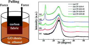
Fig. 2(a) showed the schematic diagram of the dip coating process for the self-assembled GO sheets. The equivalent pulling forces are pulling out the carbon fabrics from the GO suspension in ethanol solvent with a pulling rate of 100 μm s−1. And then the carbon fabrics containing the GO layers are dried at 70 °C. Fig. 2(b) showed the surface morphology of carbon fabric, where the smooth and crinkled stripes were obviously presented along the axial direction of the carbon fibers.20 As a comparison, after coated GO layers, the coarse surface of carbon fabrics are owing to the representative layered structures from the self-assembled GO sheets, as shown in Fig. 2(c)–(f). It is obviously demonstrated that the GO layers covered on the surfaces of the carbon fibers are increased with the increase of cycles. Furthermore, most of the GO sheets are assembled and oriented along in axial direction of the carbon fiber.21 Due to no using of modified agents, we can directly examine the enhancement effects of these self-assembled GO sheets as the interfacial layers between the carbon fabrics and PI matrix.
 |
| Fig. 2 (a) Schematic diagram of the dip coating process for self-assembled GO sheets on the carbon fabrics. SEM images of (b) original carbon fiber, carbon fiber coated by the GO interlayers for (c) 5, (d) 10, (e) 15 and (f) 20 cycles. | |
To determine the GO structures loading on the carbon fabrics, XRD patterns were performed on before and after coating on the GO interlayers with different cycles, as shown in Fig. 3. All the patterns possess a similar obvious peak at 2θ = 26.1° (d-spacing value is 3.53 Å), which are assigned to the feature diffraction peak of the carbon fibers.22 The GO sheets have a broad peak centralized at 2θ = 11.8° (d-spacing value is 7.49 Å).23 The intensity ratios of GO sheets and carbon fibers provided an enhancement with the cycles increasing from 5 to 20. It indicated that the self-assembled GO sheets were well covered on the surfaces of carbon fabrics, due to no impurity peaks.
 |
| Fig. 3 XRD patterns of the carbon fabrics and carbon fabrics coated by GO interlayers with different cycles. | |
Polyimide and its composites are well-known high performance materials with outstanding mechanical properties.24 The CF/PI composites before and after coating of self-assembled GO sheets were prepared by compression moulding. Fig. 4(a) and (b) showed the flexural strength and bending modulus with the increase of cycles, respectively. Obviously, changes of these bending properties were depended on the thickness of GO interlayers. The different dip coating cycles cause the thickness of GO interlayers to increase approximately from 50 nm to 200 nm, corresponding to 5 to 20 cycles.25 The flexural strength and bending modulus of CF/PI composite are 592 ± 13 MPa and 65.9 ± 1.3 GPa. After coating of the GO interlayers for 5 cycles, it is noted that the values of mechanical properties are 681 ± 17 MPa (flexural strength) and 68.9 ± 1.7 GPa (bending modulus), which are higher than that of others cycles. For 15 cycles and more, the mechanical properties were below the non-coated CF/PI composite. The reason was that the GO interlayers produced the dislocation and deformation, thus, caused the decrease of the bending properties.26
 |
| Fig. 4 (a) The relationships for CF/PI composites between the flexural strength and cycles, (b) the relationships for CF/PI composites between the bending modulus and cycles. SEM micrographs of the fracture surfaces of the (c) and (d) CF/PI composites, the CF/GO/PI composites with (e) 5, (f) 10, (g) 15 and (h) 20 cycles. | |
The observations for fractural morphologies are a valuable technique to examine the fracture behaviours of the carbon fiber/fabrics reinforced polymer (CFRP) composites. Fig. 4(c)–(h) shows the SEM micrographs of the fracture surfaces of the CF/PI and CF/GO/PI composites with different cycles. The fracture mode of CF/PI composites (in Fig. 4(c) and (d)) was caused by the extraction of carbon fibers, which indicated the CF/PI composites had a weaker interfacial strength and worse comparability for the carbon fiber and matrix. With the cycles increasing from 5 to 20 (in Fig. 4(e)–(h)), the fracture modes of CF/GO/PI composites changed to the interfacial delaminating damages.27–29 Combined with the flexural strength and bending modulus, it confirmed that GO interlayers were the high strength interlayers for carbon fiber and PI matrix. For the thinner GO layers (5 cycles), the hard interfaces are presented in the CF/PI composites, causing the increase of mechanical properties. However, due to the deformation of the GO interlayers, the thicker interlayers (15 and 20 cycles) would reduce the enhanced effects of GO interlayers.30 It is important evidence that the GO interlayers below 10 cycles would play an enhanced role to improve the mechanical properties of these CF/PI composites.
To confirm the enhancement of GO layers, the interfacial wettability of various carbon fabrics was measured by the static contact angles with the 50 wt% PI solution in DMF. The testing results are shown in Fig. 5. It demonstrated that the static contact angle between the pure carbon fabric and PI solution is 23.5°, due to the non-polarity surfaces on carbon fabrics. After coating GO interlayers, the modified carbon fabrics of 5, 10, 15 and 20 cycles displayed the static contact angles of 14.9°, 13.8°, 16.3° and 19.5°, respectively, less than that of the pure carbon fabric. Because the surface of GO sheets presents a great number of hydrophilic functional groups, i.e. epoxy, carbonyl and hydroxyl, these functional groups could improve the compatibility between carbon fabrics and PI solution.31 However, with the increase of cycles, the wrinkling appeared on the surfaces of the GO interlayers could increase the surface roughness, which cause the increase of contact angles.32
 |
| Fig. 5 Contact angles between different carbon fabrics and PI solution in DMF. | |
Furthermore, the interfacial properties could be supplied by the work of adhesion and interfacial energy between carbon fabrics and PI solution. The contact angles could be calculated by Young's eqn (1):33,34
|
γs = γsl + γ1 cos θ
| (1) |
The work of adhesion between the solid surface and liquid could be calculated by the eqn (2) as follow:
where
γs,
γl and
γsl are the surface free energies of carbon fabrics, PI solution and their solid–liquid interfaces. The
γl value is approximately 54.55 mN m
−1, as reported in the literature.
35 θ is the static contact angle.
Wsl is the work of adhesion between the carbon fabrics and PI solution in DMF.
According to these two equations, the work of adhesion could also be resulted by the eqn (3) as follow:
|
Wsl = γ1(1 + cos θ)
| (3) |
The works of adhesion between carbon fabrics coated by GO layers and PI solution were much larger than the pure carbon fabric and PI solution. Moreover, the Wsl values of these fabrics were derived as follows: 106.3 mN m−1 for pure carbon fabric, 109.0 mN m−1 for 5, 109.3 mN m−1 for 10, 108.6 mN m−1 for 15 and 107.7 mN m−1 for 20 GO layers (20 times) on the carbon fabrics. Therefore, these GO interlayers could improve the compatibility and enhance the interfacial strength between carbon fabrics and PI matrix.
Conclusions
The CF/PI composites with different GO sheets as interfacial layers were successfully fabricated from the dip coating process and compression moulding. The XRD and SEM results displayed the GO sheets were effectively coated on the carbon fabrics. Furthermore, the bending properties have obvious enhancements with the increase of cycles, i.e. the flexural strength and bending modulus from 592 ± 13 MPa and 65.9 ± 1.3 GPa for pure CF/PI composites to 681 ± 17 MPa and 68.9 ± 1.7 GPa for CF/GO/PI composites with 5 cycles, respectively. Meanwhile, the fracture modes are changed from the extraction of carbon fibers to the interfacial delaminating damages by the fractural morphologies. The carbon fabrics with the GO interlayers displayed outstanding interfacial properties, to enhance the wettability and interfacial strength between carbon fabrics and PI matrix.
Acknowledgements
We thank the National Natural Science Foundation of China (no. 51010005, 91216123, 51174063), the program for New Century Excellent Talents in University (NCET-08-0168). Natural Science Funds for Distinguished Young Scholar of Heilongjiang Province. The project of International Cooperation supported by Ministry of Science and Technology of China (2010DFR50160).
Notes and references
- M. Kawai, S. Yajima, A. Hachinohe and Y. Kawase, Compos. Sci. Technol., 2001, 61, 1285–1302 CrossRef CAS.
- X. R. Zhang, X. Q. Pei and Q. H. Wang, J. Mater. Sci., 2008, 43, 4567–4572 CrossRef CAS PubMed.
- J. F. Xie, D. W. Xin, H. Y. Cao, C. T. Wang, Y. Zhao, L. Yao, F. Ji and Y. P. Qiu, Surf. Coat. Technol., 2011, 206, 191–201 CrossRef CAS PubMed.
- J. M. He and Y. D. Huang, J. Appl. Polym. Sci., 2007, 106, 2231–2237 CrossRef CAS.
- J. Li and Z. S. Xu, Materialwiss. Werkstofftech., 2010, 41, 106–110 CrossRef CAS.
- X. R. Zhang, X. Q. Pei and Q. H. Wang, Mater. Chem. Phys., 2009, 115, 825–830 CrossRef CAS PubMed.
- C. Wang, J. Wang and Y. A. Niu, Adv. Compos. Lett., 2007, 16, 237–241 Search PubMed.
- Y. Z. Chang, G. Y. Han, M. Y. Li and F. Gao, Carbon, 2011, 49, 5158–5165 CrossRef CAS PubMed.
- X. Q. Zhang, X. Y. Fan, C. Y. Yan, H. Z. Li, Y. D. Zhu, X. T. Li and L. P. Yu, ACS Appl. Mater. Interfaces, 2012, 4, 1543–1552 CAS.
- Y. Z. Liu, Y. F. Li, Y. G. Yang, Y. F. Wen and M. Z. Wang, New Carbon Mater., 2012, 27, 377–384 CAS.
- H. Qian, A. Bismarck, E. S. Greenhalgh and M. S. P. Shaffer, Composites, Part A, 2010, 41, 1107–1114 CrossRef PubMed.
- A. P. Singh, P. Garg, F. Alam, K. Singh, R. B. Mathur, R. P. Tandon, A. Chandra and S. K. Dhawan, Carbon, 2012, 50, 3868–3875 CrossRef CAS PubMed.
- M. K. van der Lee, A. J. van Dillen, J. H. Bitter and K. P. de Jong, J. Am. Chem. Soc., 2005, 127, 13573–13582 CrossRef CAS PubMed.
- Y. A. Niu, J. P. Zhao, X. Zhang, X. J. Wang, J. Wu, Y. Li and Y. Li, Appl. Phys. Lett., 2012, 101, 181903 CrossRef PubMed.
- Y. W. Zhu, S. Murali, W. W. Cai, X. S. Li, J. W. Suk, J. R. Potts and R. S. Ruoff, Adv. Mater., 2010, 22, 3906–3924 CrossRef CAS PubMed.
- L. Wang, J. J. Zhao, Y. Y. Sun and S. B. B. Zhang, J. Chem. Phys., 2011, 135, 184503 CrossRef PubMed.
- K. N. Kudin, B. Ozbas, H. C. Schniepp, R. K. Prud'homme, I. A. Aksay and R. Car, Nano Lett., 2008, 8, 36–41 CrossRef CAS PubMed.
- H. L. Wang, J. T. Robinson, X. L. Li and H. J. Dai, J. Am. Chem. Soc., 2009, 131, 9910–9911 CrossRef CAS PubMed.
- M. F. Zhu, C. Q. Zeng and J. S. Ye, Electroanalysis, 2011, 23, 907–914 CrossRef CAS.
- Z. S. Dai, B. Y. Zhang, F. H. Shi, M. Li, Z. G. Zhang and Y. Z. Gu, Appl. Surf. Sci., 2011, 257, 8457–8461 CrossRef CAS PubMed.
- Z. Q. Yao, M. S. Zhu, F. X. Jiang, Y. K. Du, C. Y. Wang and P. Yang, J. Mater. Chem., 2012, 22, 13707–13713 RSC.
- N. Padmavathi, J. Subrahmanyam, K. K. Ray, R. Mohanrao, P. Ghosal and S. Kumari, J. Mater. Process. Technol., 2008, 204, 434–439 CrossRef CAS PubMed.
- S. Morimune, T. Nishino and T. Goto, Polym. J., 2012, 44, 1056–1063 CrossRef CAS.
- D. Chen, R. Y. Wang, W. W. Tjiu and T. X. Liu, Compos. Sci. Technol., 2011, 71, 1556–1562 CrossRef CAS PubMed.
- X. Y. Peng, X. X. Liu, D. Diamond and K. T. Lau, Carbon, 2011, 49, 3488–3496 CrossRef CAS PubMed.
- O. C. Compton and S. B. T. Nguyen, Small, 2010, 6, 711–723 CrossRef CAS PubMed.
- H. Y. L. S. Kobayashi, D. S. Brauer and C. Rüssel, Mater. Sci. Eng., C, 2010, 30, 1003–1007 CrossRef CAS PubMed.
- Y. Li, N. Hori, M. Arai, N. Hu, Y. L. Liu and H. Fukunaga, Composites, Part A, 2009, 40, 2004–2012 CrossRef PubMed.
- M. Arai, Y. Noro, K.-I. Sugimoto and M. Endo, Compos. Sci. Technol., 2008, 68, 516–525 CrossRef CAS PubMed.
- I. K. Moon, J. I. Kim, H. Lee, K. Hur, W. C. Kim and H. Lee, Sci. Rep., 2012, 3, 1112 Search PubMed.
- D. R. Dreyer, S. J. Park, C. W. Bielawski and R. S. Ruoff, Chem. Soc. Rev., 2010, 39, 228–240 RSC.
- B. Yuan, T. Zhu, Z. X. Zhang, Z. Y. Jiang and Y. Q. Ma, J. Mater. Chem., 2011, 21, 3471–3476 RSC.
- S. R. Wang, Y. Zhang, N. Abidi and L. Cabrales, Langmuir, 2009, 25, 11078–11081 CrossRef CAS PubMed.
- J. Rafiee, X. Mi, H. Gullapalli, A. V. Thomas, F. Yavari, Y. F. Shi, P. M. Ajayan and N. A. Koratkar, Nat. Mater., 2012, 11, 217–222 CrossRef CAS PubMed.
- H. J. Yuan, S. C. Zhang, C. X. Lu, S. Q. He and F. An, Appl. Surf. Sci., 2013, 279, 279–284 CrossRef CAS PubMed.
|
This journal is © The Royal Society of Chemistry 2014 |
Click here to see how this site uses Cookies. View our privacy policy here.