Self-assembled synthesis of carbon-coated Fe3O4 composites with firecracker-like structures from catalytic pyrolysis of polyamide

Junhao Zhang*ac, Bo Yana, Hui Wub and Qinghong Kong*b
aSchool of Biological and Chemical Engineering, Jiangsu University of Science and Technology, Zhenjiang, Jiangsu 212018, China. E-mail: jhzhang6@mail.ustc.edu.cn; Fax: +86 511 88790933; Tel: +86-511-88782960
bSchool of the Environment and Safety Engineering, Jiangsu University, Zhenjiang, Jiangsu 212013, China. E-mail: kongqh@ujs.edu.cn
cCAS Key Laboratory of Materials for Energy Conversion, University of Science and Technology of China, Hefei, Anhui 230026, China

Received 17th November 2013 , Accepted 6th January 2014

First published on 7th January 2014


Abstract

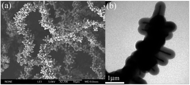
Carbon-coated Fe3O4 composites with firecracker-like structures have been fabricated by catalytic pyrolysis of polyamide (PA) in a sealed reaction system. As revealed in field-emission scanning electron microscopy (FESEM) and transmission electron microscopy (TEM) analysis, the diameter of the one-dimensional firecracker-like structures is about 4 μm and the diameter of the secondary nanorods is about 620 nm. The diameter of Fe3O4 nanorods inside the carbon shells is about 82 nm, and the thickness of the carbon shells is about 265 nm. Some important preparative parameters related to the synthesis have been identified and investigated by some designed experiments. The magnetic measurement at room temperature indicates that the values of saturation magnetization (19.2 emu g−1) and coercivity (270.1 Oe) of the carbon-coated Fe3O4 composites with firecracker-like structures are different from those of Fe3O4 nanoparticles and bulk Fe3O4 due to the different carbon content, dipolar interaction, size and morphology of the products. The results also indicate that the one-dimensional Fe3O4@C core–shell structures possess good acid resistance.

1. Introduction

Magnetite (Fe3O4) is a kind of important magnetic material and has attracted enormous research interests in lithium storage,1 targeted drug delivery,2 and water treatment.3 Due to the unique magnetic nature of Fe3O4, it has also been applied in magnetism,4 as well as magnetic resonance imaging.5 However, there are some limitations in their practical application. One is that naked Fe3O4 particles can't be used in strong acidic solution. The other important limitation is that Fe3O4 microspheres have few functional groups on their surface. As is well-known, the support for drug or catalyst must have abundant functional groups on its surface to adsorb the drug or catalyst. However, Fe3O4 nanoparticles can hardly adsorb the drugs or catalysts. Additionally, the highly active ferromagnetic nanoparticles are easily oxidized in air and tend to agglomerate for reducing the energy associated with high surface/volume ratio, which results in the loss of magnetism and dispersibility of naked ferromagnetic nanoparticles. By coating ferromagnetic nanoparticles with other materials, Fe3O4 particles can be protected from being dissolved in acid environment6 and their properties can also be tailored with different desirable functional properties such as biocompatibility or electrical conductivity or chemical and physical stability which are necessary for particular applications.7 Among them, silica has being mostly used as the coating material because it can efficiently inhibit the hydrogen ions to get through.8,9 However, inorganic silica shells also have few functional groups on their surface and must be chemically modified before being used as support for catalyst. The modification process is usually inconvenient for industrial application and the modifiers such as N-hydroxysuccinimidyl ester are usually toxic, which limit their application in drug delivery, catalyzing the degradation of water pollutants and other processes related to life science.10 For the reason, various polymers, such as polypyrrole and polyaniline, have been used as the coating material for Fe3O4 nanoparticles.11,12 Though there are always a plenty of functional groups on their surface, the gaps in the network of polymers may allow hydrogen ions to get through and dissolve the Fe3O4 cores. Consequently, it is not very appropriate to use such polymers as the coating material for Fe3O4 spheres. Compared to polymer and silica shells which were studied most, carbon shells exhibit much higher stability in various chemical and physical environments.13,14 Encapsulating ferromagnetic nanoparticles inside carbon shells is of considerable significance, because the encapsulated species can be immunized against environmental degradation effects, but also it offers an opportunity to investigate dimensionally confined systems.15,16 Such carbon coated ferromagnetic nanoparticles are expected to play a significant role in a wide range of applications. For example, serving as adsorbents,17 catalytic systems supports,18 enzyme and protein immobilization,19 and so on.

Until now, some techniques have been developed to synthesize carbon-encapsulated magnetic nanoparticles.20,21 Recently, 3D hierarchical nanostructures have attracted much attention because of their unique chemical and physical properties and great potential applications.22–26 The most efficient route to 3D nanostructures is probably self-assembly through a spontaneous process.27 However, the practical use of carbon-encapsulated magnetic nanoparticles is significantly hampered by the intrinsically high energy consumption, environmental load and economic factors of these mentioned techniques. The growing need for carbon-encapsulated magnetic nanoparticles has prompted numerous research efforts for developing effective and economic synthesis techniques. Recently, decomposition of polymer in closed systems to prepare carbon materials aroused many interests.28,29 The preparative process belongs to “green chemistry” because of the use of safe reactants and the preparative process doesn't produce pollution into environment. To the best of our knowledge, there have been few reports about the synthesis of complex Fe3O4@C hierarchical structures.

Herein, we demonstrate the design and synthesis of carbon-coated Fe3O4 composites with firecracker-like structures from PA as carbon source without solvents via a simple and economical catalytic pyrolysis process at lower temperature (500 °C). Thus, 1D magnetic structure with novel morphology was obtained. Importantly, the carbon-coated Fe3O4 architecture exhibits well acid resistance and have a higher coercivity (Hc) value. Furthermore, potential applications of the complex firecracker-like architectures have also been addressed on the basis of the unique physicochemical properties.

2. Experimental section

In a typical procedure, PA (1.0 g), ferrocene (0.5 g) and ammonium acid carbonate (1.0 g) were loaded into a stainless steel autoclave of 20 mL capacity. The autoclave was sealed and put into an electronic furnace, and the temperature of the furnace was increased to 500 °C in 50 minutes and maintained at 500 °C for 12 h. Then, the autoclave was cooled to room temperature naturally. It was found that the final products in the autoclave were dark precipitates and residual gases. The black precipitates were collected and divided into two parts: one part was washed with distilled water and ethanol for several times, and the other part was heated in HCl solution of about 3 mol L−1 at 80 °C for 2 h and washed with distilled water and ethanol for several times. Afterwards, the products were dried in a vacuum box at 50 °C for 4 h, and were collected for characterization.

The X-ray powder diffraction (XRD) pattern of the products without acid treatment was recorded on a Rigaku (Japan) D/max-γA X-ray diffractometer equipped with graphite-monochromatized Cu Kα radiation (λ = 1.54178 Å). The Raman spectra were recorded at ambient temperature on a SPEX 1403 spectrometer with an argon-ion laser at an excitation wavelength of 514.5 nm. X-ray photoelectron spectroscopy (XPS) of the products was performed using a VGESCALABMK X-ray photoelectron spectrometer and non-monochromated Mg radiation as the excitation source. The field-emission scanning electron microscopy (FESEM) images of the products were examined by a field-emission scanning electron microscope (JEOL-6300F). The transmission electron microscope (TEM) images, high resolution transmission electron microscope (HRTEM) image were taken on a JEOL 2010 high-resolution transmission electron microscope at an acceleration voltage of 200 kV. Element dispersive spectrometric (EDS) analysis was carried out on an X-ray energy spectrum instrument equipped with INCA300 (Oxford). The magnetic properties (MH curve) were measured at room temperature on an MPMS XL magnetometer made in Quantum Design Corporation.

3. Results and discussion

To ascertain the component and structure of the products, XRD was used to investigate the crystal phases of the products before acid treatment. Fig. 1a shows a XRD pattern of the products before acid treatment. The sharp diffraction peaks with relative high peak intensity were indexed as crystalline face-centered cubic (fcc) Fe3O4 (JCPDS Card no. 85-1436), while there is a broad peak with low peak intensity at 2θ = 22–26°, corresponding to the noncrystalline carbon phase. No other noticeable peaks induced by impurities can be observed in the XRD pattern. Raman spectrum is a standard nondestructive tool for the characterization of carbon materials, particularly to determine the graphitization degree.30 Fig. 1b gives the corresponding Raman spectra, showing two similar Raman bands at 1341 cm−1 (D band) and 1593 cm−1 (G band). More specifically, the two peaks exhibit an E2g mode of graphite related to the vibration of sp2-bonded carbon atoms in a 2D hexagonal lattice (such as in a graphene layer) and A1g mode of graphite related to the disorder features due to the finite particle size effect or lattice distortion of the graphite crystals. The relative intensity ratio of the D-G band, ID/IG, can give reliable information for the graphitization degree.30 It is found that the carbon-coated Fe3O4 composites have a higher ID/IG, implying a highly disordered graphitic structure for carbon shells, and these results are consistent with the XRD pattern.
image file: c3ra46764c-f1.tif
Fig. 1 (a) XRD pattern of carbon-coated Fe3O4 composites with firecracker-like structures; (b) Raman spectrum of carbon-coated Fe3O4 composites with firecracker-like structures.

In order to analyze the surface component of the carbon-coated Fe3O4 composites, X-ray photoelectron spectra of the products was measured. The XPS of carbon-coated Fe3O4 composites with firecracker-like structures are shown in Fig. 2. It can be found that the peaks on the full pattern are mainly attributed to C1s (284.5 eV), O1s (533.2 eV) and their corresponding Auger peaks. However, there are almost no peaks for the Fe2p binding energy detected, suggesting that Fe3O4 nanorods are completely encapsulated in thicker carbon layers. Quantitative analysis reveals that the molar ratio of C/O/Fe is 95.45/4.26/0.28. The high percent of element O may come from the oxygen containing groups on the carbon shells.


image file: c3ra46764c-f2.tif
Fig. 2 X-ray photoelectron spectra of Fe3O4@C core–shell structures: (a) a wide scan spectrum; (b) high-resolution XPS spectrum of C 1s region; (c) high-resolution XPS spectrum of Fe 2p region; (d) high-resolution XPS spectrum of O 1s region.

Iron oxides encapsulated in carbon based systems have attracted increasing attention due to their electric and magnetic properties and their variety of potential technological application. In recent years, there have been a number of studies of iron oxides and carbon composites. Among them, nanoparticles, nanowires, nanoplates and hexapod-like microstructures have been synthesized. In Fig. 3a, another type of Fe3O4 and carbon composites is presented in high morphological yield. The composites are one-dimensional firecracker-like structures, which were assembled by nanorods. The diameter of one-dimensional firecracker-like structures is about 4 μm and the diameter of secondary nanorods is about 620 nm. The structures were further characterized by TEM. Fig. 3b and c are TEM images before acid treatment, which indicates that the nanorods are core–shell structures, which made of two parts: the outer shell (carbon) and the inner core (Fe3O4). Careful observation shows that the diameter of Fe3O4 nanorods inside carbon shell is about 82 nm, and the thickness of carbon shells is about 265 nm. From the results of the HRTEM image of carbon shells in Fig. 3d, no obvious lattice images are observed on the shells, indicating their low crystallization. The chemical composition of carbon-coated Fe3O4 composites was analyzed using an element dispersive spectrometer attached to a high-resolution electron microscope. The results of EDS in Fig. 3e confirm that Fe, O and C elements are presented in the composites. The signals of Cu element come from the supporting TEM grid during measurements. It is noteworthy mentioning that the Fe3O4 nanorods are still in the carbon shells after acid treatment, shown in Fig. 3f, which indicates that the Fe3O4@C core–shell structures possess well acid resistance.


image file: c3ra46764c-f3.tif
Fig. 3 (a) FESEM image of carbon-coated Fe3O4 composites with firecracker-like structures; (b) low magnification TEM image of carbon-coated Fe3O4 composites with firecracker-like structures before acid treatment; (c) high magnification TEM image of carbon-coated Fe3O4 composites with firecracker-like structures before acid treatment; (d) HRTEM image of carbon shell; (e) EDS of spectrum of carbon-coated Fe3O4 composites with firecracker-like structures before acid treatment; (f) TEM image of carbon-coated Fe3O4 composites with firecracker-like structures after acid treatment.

To understand the possible formation process of the carbon-coated Fe3O4 composites, a series of relevant experiments were carried out by altering the experimental parameters. Several factors were found to influence the morphology of the composites: reaction temperature, dose of NH4HCO3, and reaction atmosphere. According to the previous study, carbonization of polymer is a pyrolysis, dehydrogenation and cross-linking process, which is greatly affected by reaction temperature. When the reaction temperature was 500 °C, the reaction rate was lower, and the obtained Fe3O4 and carbon atoms were self-assembled to carbon-coated Fe3O4 composites with firecracker-like structures, shown in Fig. 3. Fig. 4 shows FESEM images of the products obtained at 600 °C and 700 °C. It is found that there are two types of structures at 600 °C. Fig. 4a shows that carbon-coated Fe3O4 microparticles are the main products, which are stacked together. Besides them, carbon microspheres are also the products, as shown in Fig. 4b. By increasing the reaction temperature to 700 °C, the products also include two kinds of structures. Fig. 4c shows that the carbon-coated Fe3O4 particles are the products, and the main size of particles is about 500 nm. Fig. 4d reveals that the products are also composed of mats-like structures self-assembled by flat carbon nanotubes. It is generally known that the nucleation rate of Fe3O4 was accelerated, so large Fe3O4 particles were formed, and part of carbon atoms were deposited on the surface of Fe3O4 particles and other carbon atoms formed carbon structures such as carbon microspheres and mats-like structures.


image file: c3ra46764c-f4.tif
Fig. 4 (a) and (b) FESEM images of the products obtained at 600 °C for 12 h; (c) and (d) FESEM images of the products obtained at 700 °C for 12 h.

Fig. 5 shows the FESEM images of carbon and Fe3O4 composites prepared at 500 °C for 12 h with different doses of NH4HCO3. In the absence of NH4HCO3, Fig. 5a and b show that the products have one-dimensional and worm-like morphology with smooth surface, and have a length about 60 μm and a diameter about 4 μm. As 0.5 g of NH4HCO3 is added, the main products are one-dimensional and firecracker-like structures, and nanorods have the length about 1.2 μm and the diameter about 750 nm, as shown in Fig. 5c and d. When the amount of NH4HCO3 is 2 g, the FESEM images in Fig. 5e and f for the products show abundant one-dimension structures, being tens of micrometers in length. In fact, it is hard for us to discern where the chains' ends are, because they almost attach together.


image file: c3ra46764c-f5.tif
Fig. 5 (a) and (b) FESEM images of the products obtained without NH4HCO3; (c) and (d) FESEM images of the products obtained with 0.5 g NH4HCO3; (e) and (f) FESEM images of the products obtained with 2 g NH4HCO3.

Apart from the reaction temperature and amount of NH4HCO3, the composites can also be tuned by varying reaction atmosphere. Fig. 6 and 7 show the morphologies and components of the products using H2O, CO(NH2)2, CS(NH2)2 and NaN3 replacing NH4HCO3. From the results, it is found that the reaction atmosphere influence the components and morphologies. When H2O was used to replace NH4HCO3, Fig. 6a shows that the products are one-dimensional and worm-like structures with the diameter of about 600 nm, and Fig. 7a indicates the products are the composites of C and Fe3O4 (JCPDS Card no. 85-1436). In this system, PA decomposed to produce small molecules carbonyl compounds as carbon source in the absence of oxygen, and Fe atoms were released by decomposition of ferrocene to act as dehydrogenation catalyst. As-formed Fe atoms reacted with H2O to form Fe3O4 nanoparticles with high reaction rate due to the presence of large amounts of water vapor, and the obtained Fe3O4 particles were self-assembled to chain-like structures under the drive of magnetic dipole interaction. The small molecules carbonyl compounds were carbonized to produce carbon atoms, which precipitated on the surface of Fe3O4 chains to form worm-like structures. When NH4HCO3 was replaced by CO(NH2)2, Fe atoms by decomposition of ferrocene acted as dehydrogenation catalyst of the small molecules carbonyl compounds and form a large number of carbon atoms. Because the Fe atoms were oxidized with low reaction rate in the atmosphere of NH3 and HCNO by decomposition of CO(NH2)2, the carbon atoms grew to carbon nanostructures for decreasing the energy of the system before formation of Fe3O4. From Fig. 6b, the products are large amounts of flake-like structures and nanoparticles. Fig. 7b reveals that the products are the composites of C and Fe3O4 (JCPDS Card no. 85-1436). When the CS(NH2)2 was used to replace NH4HCO3, the products are also flake and nanoparticles and mainly composed of C and FeS (JCPDS Card no. 65-9124), shown in Fig. 6c and 7c. The formation mechanism is similar to that of using CO(NH2)2 replacing NH4HCO3. If NaN3 replaces NH4HCO3, NaN3 decompose to release Na and N2. Fe atoms were not oxidized in the presence of Na vapor, which acted as dehydrogenation catalyst to decompose small molecules carbonyl compounds. Fig. 6d displays that the products include sponge-like structures and nanoparticles, and Fig. 7d reveals that the products are the composite of C and Fe (JCPDS 06-0696). Consequently, it can be believed that appropriate atmosphere could serve for creating products with firecracker-like structures.


image file: c3ra46764c-f6.tif
Fig. 6 (a) FESEM images of the products using H2O replacing NH4HCO3; (b) FESEM images of the products using CO(NH2)2 replacing NH4HCO3; (c) FESEM images of the products using CS(NH2)2 replacing NH4HCO3; (d) FESEM images of the products using NaN3 replacing NH4HCO3.

image file: c3ra46764c-f7.tif
Fig. 7 (a) XRD pattern of the products using H2O replacing NH4HCO3; (b) XRD pattern of the products using CO(NH2)2 replacing NH4HCO3; (c) XRD pattern of the products using CS(NH2)2 replacing NH4HCO3; (d) XRD pattern of the products using NaN3 replacing NH4HCO3.

To elucidate clearly the catalyzing carbonization mechanism of polyamide to form the carbon-coated Fe3O4 composites with firecracker-like structures, an illustrative scheme is presented in Fig. 8. At first, NH4HCO3 started to decompose and produce NH3, H2O and CO2 from 30 °C, shown in process (1). With increasing temperature, PA chains underwent endothermic chain scission to produce small molecules carbonyl compounds and other fragments in the absence of oxygen, most of which were gases at 500 °C, shown in process (2). Fe atoms were released by decomposition of ferrocene at 400 °C, shown in process (3). Meanwhile, these small molecules carbonyl compounds were catalytically decomposed to form carbon atoms under Fe atoms as catalysts, shown in process (4). Then, as-formed Fe atoms gradually reacted with H2O and CO2 to form Fe3O4 and assemble to firecracker-like structures, shown in process (5). These Fe3O4 firecracker-like structures were speedy wrapped by a small number of carbon atoms (forming a thin carbon lamella) to reduce their surface energy, and form Fe3O4 encapsulated in thin carbon capsules. These thin carbon lamella confined the continued growth of Fe3O4 structures. As carbon atoms are enough in these experiments, the continued addition (or diffusion) of carbon atoms finally leads to the formation of firecracker-like Fe3O4@C core–shell structures. On the whole, Fe atoms by decomposition of ferrocene acted as dehydrogenation catalyst, and PA were decomposed catalytically to form carbon atoms and coat on Fe3O4 by a dissociation–diffusion–precipitation process.


image file: c3ra46764c-f8.tif
Fig. 8 Mechanism for the formation of Fe3O4@C composites with firecracker-like structures through catalytic pyrolysis.

In many reported Fe3O4 nanostructures, a significant enhancement in ferromagnetic character has been observed. The observed increase in coercivity (Hc) of products has been attributed to the increase in structural anisotropy and one-dimensional structures. The magnetic properties were investigated at room temperature with an applied field from −10[thin space (1/6-em)]000 Oe to 10[thin space (1/6-em)]000 Oe, shown in Fig. 9. The magnetic hysteresis loop of carbon-coated Fe3O4 composites with firecracker-like structures shows ferromagnetic behavior with saturation magnetization (Ms), remanent magnetization (Mr), and coercivity (Hc) values of ca. 19.2 emu g−1, 3.7 emu g−1 and 270.1 Oe in Fig. 9a. From the results, the saturation magnetization value of the products is lower than that of bulk Fe3O4 (85–100 eum g−1), but higher than those of previously reported Fe3O4–C nanowires (5.11 emu g−1) and Fe3O4–C microrods (0.91 emu g−1).31,32 The decrease in the value of Ms found in this work might be most likely attributed to the wide existence of carbon layers on the surface of Fe3O4 nanorods. These carbon layers restrict the optional movement and interactions of the Fe3O4 nanorods. Its role is similar to that of the surfactant that existed on the Fe3O4 nanorods, which leads to decreased Ms value.33 The results of burring experiments indicate that the calculated Fe3O4 to Fe3O4@ carbon composites mass ratio of the products is about 0.2065. The high shape anisotropy of the Fe3O4 nanorods and the presence of a detrimental surface/crystal-structure are also related to the demagnetization effects. Additionally, the Hc value is higher than that of bulk Fe3O4, and Fe3O4–C nanocapsules (179.4 Oe),34 but lower than those of previously reported Fe3O4–C coaxial nanofibers (324.5 Oe).35 The reason may be that the higher shape anisotropy, together with reduced size,36 is responsible for the increase in Hc value compared with bulk Fe3O4. The high shape anisotropy of the nanorods prevents them from magnetizing in directions other than along easy magnetic axes. With nanorods randomly oriented, the projection of magnetization vectors along the field direction will be lower than that of nanoparticles with the large shape anisotropy effect. When compared with coaxial nanofibers with single crystalline Fe3O4 nanowires, the carbon-coated Fe3O4 composites with firecracker-like structures have lower shape anisotropy, resulting in the decrease of the Hc value. Fig. 9b shows that the results after acid treatment are similar to those before acid treatment, so it is confirmed that the Fe3O4@C core–shell structures possess well acid resistance. The Fe3O4@C composites may be used in acidic medium, such as adsorbing pollutant in acidic waste water, which also can be easily separated from water by applying a relatively low magnetic field.


image file: c3ra46764c-f9.tif
Fig. 9 Magnetic hysteresis loops of carbon-coated Fe3O4 composites with firecracker-like structures at room temperature: (a) before acid treatment; (b) after acid treatment.

4. Conclusions

In summary, Fe3O4@C composites with firecracker-like structures were synthesized by controlling the reaction temperature and amount of NH4HCO3 through catalytic decomposition of polyamide. The encapsulated Fe3O4 nanorods were self-assembled into one-dimension firecracker-like structures; and the diameter of Fe3O4 nanorods inside carbon shell is about 82 nm, and the thickness of carbon shells is about 265 nm. Magnetic hysteresis loop measurement shows that the Fe3O4@C core–shell structures display ferromagnetic properties at room temperature, and the saturation magnetization value (19.2 emu g−1) is lower than that of bulk Fe3O4, and the coercivity (Hc) value (270.1 Oe) is higher than those of Fe3O4 nanoparticles and bulk Fe3O4, which can be attributed to the wide existence of carbon layers, higher shape anisotropy and reduced size of the Fe3O4@C composites. The results of magnetic properties reveal that the Fe3O4@C core–shell structures possess well acid resistance because the Fe3O4 nanoparticles were not dissolved in HCl solution of about 3 mol L−1 at 80 °C for 2 h. The Fe3O4@C composites with firecracker-like structures have good potential application due to their unique structural features and other physicochemical properties.

Acknowledgements

The work was financially supported by Natural Science Foundation of the Higher Education Institutions of Jiangsu Province (no. 13KJB430012), the China Postdoctoral Science Foundation (no. 2012M511210), the research fund of Key Laboratory for Advanced Technology in Environmental Protection of Jiangsu Province (no. AE201104), the Opening Project of CAS Key Laboratory of Materials for Energy Conversion, and Natural Science of Foundation of China (no. 51203069).

References

  1. J. S. Xu and Y. J. Zhu, ACS Appl. Mater. Interfaces, 2012, 4, 4752 CAS.
  2. B. Chertok, B. A. Moffat, A. E. David, F. Q. Yu, C. Bergemann, B. D. Ross and V. C. Yang, Biomaterials, 2008, 29, 487 CrossRef CAS PubMed.
  3. D. P. Zhang, C. H. Lu, Y. R. Ni, Z. Z. Xu and W. B. Zhang, CrystEngComm, 2013, 15, 4755 RSC.
  4. J. Su, M. H. Cao, L. Ren and C. W. Hu, J. Phys. Chem. C, 2011, 115, 14469 CAS.
  5. S. H. Xuan, F. Wang, J. M. Y. Lai, K. W. Y. Sham, Y. X. J. Wang, S. F. Lee, J. C. Yu, C. H. K. Cheng and K. C. F. Leung, Appl. Mater. Interfaces, 2011, 3, 237 CrossRef CAS PubMed.
  6. J. H. Zhang, B. Yan, S. Wan and Q. H. Kong, Ind. Eng. Chem. Res., 2013, 52, 5708 CrossRef CAS.
  7. T. Amna, M. S. Hassan, H. V. Ba, M. S. Khil, H. K. Lee and I. H. Hwang, Mater. Sci. Eng., C, 2013, 33, 707 CrossRef CAS PubMed.
  8. H. L. Ding, Y. X. Zhang, S. Wang, J. M. Xu, S. C. Xu and G. H. Li, Chem. Mater., 2012, 24, 4572 CrossRef CAS.
  9. F. Wang, G. M. Pauletti, J. T. Wang, J. M. Zhang, R. C. Ewing, Y. L. Wang and D. L. Shi, Adv. Mater., 2013, 25, 3485 CrossRef CAS PubMed.
  10. U. S. Patil, H. Qu, D. Caruntu, C. J. O'Connor, A. Sharma, Y. Cai and M. A. Tarr, Bioconjugate Chem., 2013, 24, 1562 CrossRef CAS PubMed.
  11. M. Bhaumik, A. Maity, V. V. Srinivasu and M. S. Onyango, J. Hazard. Mater., 2011, 190, 381 CrossRef CAS PubMed.
  12. C. K. Cui, Y. C. Du, T. H. Li, X. Y. Zheng, X. H. Wang, X. J. Han and P. Xu, J. Phys. Chem. B, 2012, 116, 9523 CrossRef CAS PubMed.
  13. X. B. Zhang, H. W. Tong, S. M. Liu, G. P. Yong and Y. F. Guan, J. Mater. Chem. A, 2013, 1, 7488 CAS.
  14. L. L. Wang, J. W. Liang, Y. C. Zhu, T. Mei, X. Zhang, Q. Yang and Y. T. Qian, Nanoscale, 2013, 5, 3627 RSC.
  15. J. L. Cheng, B. Wang, C. M. Park, Y. P. Wu, H. Huang and F. D. Nie, Chem. – Eur. J., 2013, 19, 9866 CrossRef CAS PubMed.
  16. F. Y. Cao, C. L. Chen, Q. Wang and Q. W. Chen, Carbon, 2007, 45, 727 CrossRef CAS PubMed.
  17. W. Fan, W. Gao, C. Zhang, W. W. Tjiu, J. S. Pan and T. X. Liu, J. Mater. Chem., 2012, 22, 25108 RSC.
  18. Q. An, M. Yu, Y. T. Zhang, W. F. Ma, J. Guo and C. C. Wang, J. Phys. Chem. C, 2012, 116, 22432 CAS.
  19. S. Wang, H. M. Bao, P. Y. Yang and G. Chen, Anal. Chim. Acta, 2008, 612, 182 CrossRef CAS PubMed.
  20. Z. X. Wu, W. Li, P. A. Webley and D. Y. Zhao, Adv. Mater., 2012, 24, 485 CrossRef CAS PubMed.
  21. H. Y. Niu, Y. X. Wang, X. L. Zhang, Z. F. Meng and Y. Q. Cai, ACS Appl. Mater. Interfaces, 2012, 4, 286 CAS.
  22. D. K. Ma, J. L. Jiang, J. R. Huang, D. P. Yang, P. Cai and L. J. Zhang, Chem. Commun., 2010, 46, 4556 RSC.
  23. L. T. Kang, Z. C. Wang, Z. W. Cao, Y. Ma, H. B. Xu and J. N. Yao, J. Am. Chem. Soc., 2007, 129, 7305 CrossRef CAS PubMed.
  24. X. C. Gui, J. Q. Wei, K. L. Wang, A. Y. Cao, H. W. Zhu and Y. Jia, Adv. Mater., 2010, 22, 617 CrossRef CAS PubMed.
  25. Z. H. Tang, S. L. Shen, J. Zhuang and X. Wang, Angew. Chem., Int. Ed., 2010, 49, 4603 CrossRef CAS PubMed.
  26. M. Rutkowska, L. Chmielarz, D. Macina, B. Dudek, C. Van Oers, P. Cool and J. Chin, Adv. Mater. Soc., 2013, 1, 48 Search PubMed.
  27. B. Pokroy, S. H. Kang, L. Mahadevan and J. Aizenberg, Science, 2009, 323, 237 CrossRef CAS PubMed.
  28. J. H. Zhang, J. Du, Y. T. Qian and S. L. Xiong, Mater. Res. Bull., 2010, 45, 15 CrossRef PubMed.
  29. J. H. Zhang, B. Yan and F. Zhang, CrystEngComm, 2012, 14, 3451 RSC.
  30. A. C. Ferrari and J. Robertson, Phys. Rev. B: Condens. Matter Mater. Phys., 2000, 61, 14095 CrossRef CAS.
  31. L. Q. Xu, W. Q. Zhang, Y. W. Ding, Y. Y. Peng, S. Y. Zhang, W. C. Yu and Y. T. Qian, J. Phys. Chem. B, 2004, 108, 10859 CrossRef CAS.
  32. L. Q. Xu, J. Du, P. Li and Y. T. Qian, J. Phys. Chem. B, 2006, 110, 3871 CrossRef CAS PubMed.
  33. S. Ghosh, W. Jiang, J. D. Mcclements and B. S. Xing, Langmuir, 2011, 27, 8036 CrossRef CAS PubMed.
  34. P. Wu, N. Du, H. Zhang, J. X. Yu and D. R. Yang, J. Phys. Chem. C, 2011, 115, 3612 CAS.
  35. F. Y. Cao, C. L. Chen, Q. Wang and Q. W. Chen, Carbon, 2007, 45, 727 CrossRef CAS PubMed.
  36. J. H. L. Beal, S. Prabakar, N. Gaston, G. B. The, P. G. Etchegoig, G. Williams and R. D. Tilley, Chem. Mater., 2011, 23, 2514 CrossRef CAS.

This journal is © The Royal Society of Chemistry 2014
Click here to see how this site uses Cookies. View our privacy policy here.