Polymer-based acoustic streaming for improving mixing and reaction times in microfluidic applications

V. F. Cardoso*a, T. Knollb, T. Veltenb, L. Reboutac, P. M. Mendesa, S. Lanceros-Méndezc and G. Minasa
aCentro Algoritmi, University of Minho, Campus of Azurem 4800-058, Guimaraes, Portugal. E-mail: vanessa@dei.uminho.pt; gminas@dei.uminho.pt; pmendes@dei.uminho.pt; Fax: +351 253510189; Tel: +351 253 510190
bFraunhofer Institute Biomedical Engineering, Ensheimer Str. 48 66386 St., Ingbert, Germany. E-mail: thorsten.knoll@ibmt.fraunhofer.de; thomas.velten@ibmt.fraunhofer.de; Fax: +49 (0)6894 980-152; Tel: +49 (0)6894 980-301
cCenter/Department of Physics, University of Minho, Campus of Gualtar, 4710-057 Braga, Portugal. E-mail: lrebouta@fisica.uminho.pt; lanceros@fisica.uminho.pt; Fax: +351 253 678 981; Tel: +351 253 604 073

Received 5th November 2013 , Accepted 22nd November 2013

First published on 25th November 2013


Abstract

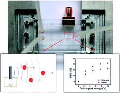
This paper reports on a polymer-based piezoelectric transducer used in microfluidic structures for generating acoustic waves, and consequently, the acoustic streaming phenomenon, that will improve the mixing of fluids. The piezoelectric transducer is based on a poly(vinylidene fluoride-trifluoroethylene), P(VDF-TrFE), copolymer with conductive transparent electrodes of aluminum doped zinc oxide (AZO). The efficiency of the optimized piezoelectric P(VDF-TrFE) transducer on mixing fluids was studied using two diagnostic kits for the quantification of uric acid and nitrite in blood. In both cases, acoustic streaming reduced the reaction time for the quantification of each biomolecule when compared to the reaction time achieved only by diffusion, with gains of 23% and of 32% for the uric acid and nitrite, respectively. These results contribute to increase the efficiency in fluid mixing and therefore to improve the overall performance of miniaturized analysis systems.

Introduction

During the last few decades, a variety of miniaturized analysis systems have been developed for areas such as medicine,1 pharmaceutical industry,2 forensic sciences3 and environmental monitoring.4 Presently, they are capable of manipulating and monitoring microliters to attoliters fluidic volumes, as well as incorporating in a fully automated platform all elements and steps of a (bio)chemical analysis.5 The large interest in this miniaturized technology comes from its advantages when compared to conventional equipments. They exhibit an improved analytical performance through fast and accurate analyses. The reduced size and portability allow the manufacture of point-of-care devices, where there is no access to appropriate laboratories or when in loco and rapid tests are required. The reduced cost when mass produced allows the fabrication of disposable devices, which avoid any contamination between analyses or exchange/miscarriage of samples. Furthermore, the low consumption of materials allows a significant reduction of waste, making them environmentally friendly.5

However, due to the small dimensions and low volumetric flow in the microfluidic structures, handling of fluids is restricted to the laminar flow regime with Reynolds numbers generally below 100.6 These features can bring critical issues for applications where the control of fluids or compounds is essential. Consequently, considerable efforts are being made in the design and the characterization of mixing and pumping systems with appropriate sizes for integration into microfluidic devices. Passive mixers were the first to be reported and rely on the pumping energy of fluids and specific microstructure geometries to handle the flow. The mixture of fluids only by diffusion and convection can result in long and complex channel topologies, which are associated with long transit and mixing times, particularly when the diffusion coefficients of the fluids or molecules are small (e.g. some enzymes and proteins).5 Active mixers are based on the application of external forces applied to the flow which accelerate the mixing process. These mixers, generally, present higher mixing efficiency when compared to passive mixers and the fact that, in some cases, they can be controlled externally makes them suitable for the microfluidic system reconfiguration. However, they are often associated with complex and costly manufacturing processes and their incorporation into microfluidic systems is likewise complex. Further, they may have moving parts that can be damaged or even cause damage when the fluids are susceptible, such as those containing cells.7

Consequently, it is necessary to develop alternative methods to provide microfluidic structures with a mechanism which accelerates fluids mixture, without moving parts, with simple and low-cost processing and easy to integrate within the device. One mechanism able to accomplish these requirements comes from the phenomenon called acoustic streaming, where ultrasonic acoustic waves propagate through fluids originating a force which causes pumping and/or mixing.8,9

In the next section, acoustic streaming will be shortly described, including its advantages and limitations for microfluidic technologies. The state-of-art will be presented, as well as the potential of piezoelectric polymers when compared to piezoelectric ceramic transducers. Then, the design and fabrication of a polymer-based piezoelectric transducer and its incorporation in a microfluidic structure will be described. The system was tested for potential clinical applications allowing the quantification of nitrite and uric acid in blood.

Acoustic streaming phenomenon

Theoretical background

Acoustic streaming can be described as any flow formed by the force resulting from the presence of a gradient in the time-average acoustic momentum flow of a fluid.8,10 Therefore, a fluid flow is created by the viscous attenuation of acoustic waves which propagate through the medium. This force is transferred without contact, an unparalleled property when compared to others active micromixers. Depending on the scale of the fluids motion, acoustic streaming can be classified into three types:11 Eckart streaming; Schlichting streaming; and Rayleigh streaming. The first, also called quartz wind, is generated in a non-uniform free sound field, whose scale is much larger than the acoustic wavelength. Therefore, the fluid flow is generated by the attenuation of the acoustic waves into the bulk of the medium. The last two are intrinsically related. Schlichting streaming is described as the vortex motion generated in a viscous boundary layer on the surface of an object placed in a sound field, whose scale is much smaller than the wavelength.12,13 Rayleigh streaming is the vortex generated outside the boundary layer in a standing wave field, whose scale is comparable to the acoustic wavelength.14

Extensive reviews on acoustic streaming and its application in microfluidic devices can be found in.12,15,16

Acoustic streaming for microfluidic applications

Acoustic streaming presents two distinct advantages for microfluidic applications. First, the flow generated by acoustic attenuation allows overcoming most of the viscous forces associated to the microscale fluidic structures. Secondly, as the channel diameter decreases the acoustic forces become more favorable due to the generation of an acoustic boundary layer flow which results in high forces in a very small area.12

Moreover, mixers and pumps based on acoustic streaming provide an increased reliability by not having moving parts and their construction is relatively simple since they can be easily fabricated or directly deposited in the microfluidic structure. The absence of holes, valves and mechanical devices avoids damage to sensitive fluids such as those with suspended cells.

Nevertheless, devices based on acoustic streaming also show limitations related to their relatively low efficiency, when compared with micropumps or microvalves. This is a second order nonlinear mechanism and, therefore, only a fraction of the acoustic energy is transferred into kinetic energy in the fluid. Moreover, only a fraction of the electrical energy applied to the piezoelectric material is converted into acoustic energy. The remaining energy is dissipated as heat. The latter may be undesirable in applications where heating is harmful but may also be advantageous in applications involving endothermic reactions, for example. In these cases, the combined action of acoustic waves and heat generated by the piezoelectric material allows to decrease the reaction time and, therefore, to obtain the results faster. Several techniques can be used to improve the efficiency of acoustic streaming including the focusing of acoustic energy through lenses17 and the introduction of air bubbles,18 among others. However, there are many applications where energy efficiency is not a priority and where the advantages of acoustic streaming-based pumping and mixing are unmatched.12,13

Piezoelectric materials for the generation of acoustic streaming

Acoustic streaming was first described by Rayleigh in 1884 (ref. 19) and subsequently developed by Eckart in 1948,20 Markham in 1952 (ref. 21) and Nyborg in 1953.22 These investigations have given rise to a new set of studies based on this phenomenon and employed in the field of miniaturized fluidic systems that allow not only mixing and pumping of fluids but also manipulating and separating particles. Yang et al.23 developed an acoustic micromixer based on lead zirconate titanate (PZT). The transducer was able to mix a solution of uranine and water in a continuous and laminar flow at a rate of 5 ml min−1. A temperature rise of 16 °C was obtained due to ultrasonic irradiation. Yaralioglu et al.6 described a fluidic micromixer based on thin films of zinc oxide (ZnO) with patterned gold electrodes deposited on the surface of a quartz substrate. The acoustic pressure generated by the transducers proved capable of mixing fluids contained inside a microfluidic channel. The same authors presented a PZT transducer coupled in the bottom wall of the microfluidic channel.24 The system was able to significantly increase the lysis of Escherichia coli K12 cells by accelerating the mixture of cell suspension and lysis reagent. Later, they demonstrated the feasibility of this method to separate particles and cells.6 Kaajakari et al.25 described a microfluidic PZT-based ultrasonic actuator capable of mixing, pumping and capturing particles. The signal actuation causes different vibration modes of the silicon structures (beams and bridges) situated inside the microfluidic reservoirs. Rife et al.26 proposed a microfluidic device which integrates a 33 μm thick barium titanate (BaTiO3) transducer to promote the mixing and pumping of fluids. Lilliehorn et al.27 presented a microfluidic system capable of capturing particles of polyamide with a diameter of 5 μm contained in a linear flow using acoustic forces at a rate not exceeding 1 mm s−1. The capture was studied using three PZT transducers integrated into the channel. The response time to capture the particles was in the order of 200 ms. Bengtsson et al.28 incorporated an ultrasonic crystal underneath a parallel channel enzyme microreactor in porous silicon. The crystal induces a Rayleigh flow transverse to the laminar flow in the microreactor. The increase in catalytic effect with acoustic streaming at 5.25 MHz was between 15 and 20%.

Considerable results have been achieved in this field in an extremely wide range of applications. Most of them are based on piezoelectric ceramics or crystals attached inside or outside microfluidic structures, with the primary purpose of manipulating fluids and/or particles without generating heat or studying its effect. However, the possible lack of transparency of these materials in combination with the use of opaque electrodes does not allow their incorporation into the light path of optical devices. Consequently, there is a need for new materials for the generation of acoustic streaming that overcome the previous limitations as well as demonstrate their potential for technological applications requiring simultaneously heating and mixing. Polymer-based transducers represent a good option since they present several properties which may be advantageous for microfluidic applications. They take advantage of characteristics such as easy processability, high mechanical strength, low weight, high flexibility and low-cost. Moreover, they are highly resistant to chemical agents and also have a high resistance to aging. All these properties give them some advantages compared to ceramic transducers. While ceramics are rigid, dense and brittle, polymer-based piezoelectric transducers are flexible, with a low density and can easily be produced as film.29 On the other hand, piezoelectric ceramics present higher piezoelectric coefficients and electromechanical coupling factors which mean they have an increased efficiency in the generation of acoustic waves. Nevertheless, if the acoustic waves are emitted in liquid or plastic much of the energy generated by the piezoceramic element is reflected in the boundary layer between the element itself and the propagation medium. This effect arises from the high acoustic impedance of ceramics when compared to liquids or plastics (1.5 to 3 × 10⁶ kg m−2), so that the reflection coefficient at the boundary layer can reach 90%. Consequently, only a fraction of the acoustic energy generated by the ceramic element is transferred to the propagation medium.30 In turn, polymer-based transducers overcome this limitation by presenting an acoustic impedance comparable to that of fluids and plastics. Another interesting feature of these materials derives from their high transparency in the visible light spectrum, allowing their integration into the light path of optical devices, when used in combination with transparent conductive electrodes.

Consequently, the low acoustic impedances of the polymer-based piezoelectric transducer allied to their good mechanical and optical properties, makes them excellent candidates for microfluidic applications.

Microfluidic and piezoelectric transducer systems design and fabrication

The polymer-based piezoelectric transducer was designed to act exclusively at the reaction chamber of a polydimethylsiloxane (PDMS) microfluidic structure. An electronic matching circuit was also designed to maximize the power transferred to the piezoelectric transducer.

All components and manufacturing steps were subjected to optimization processes and the results are described below.

Microfluidic system

The PDMS microfluidic structures were fabricated by soft lithography with outer dimensions of 30 × 15 × 4 mm3. The structures comprise a channel with inlet, outlet and a reservoir to act as reaction chamber (Fig. 1). Both the channel and the reaction chamber present a thickness of 500 μm, which is the minimum optical path length required to perform the measurements by optical absorption spectrophotometry for the quantification of uric acid and nitrite in blood.31 The reaction chamber presents an area of 1 mm2. This area is needed due to the 1 mm diameter optical fiber used as light source.
image file: c3ra46420b-f1.tif
Fig. 1 Schematic representation of the PDMS microfluidic structure. The units are in millimeters.

An acrylic and an aluminum support were also manufactured by micromachining. These two elements allow pressing the PDMS microfluidic structure against the piezoelectric transducer deposited on the glass substrate enabling full contact between them. An irreversible sealing is thus avoided, which allows the exchange of the microfluidic structure or the piezoelectric transducer of the system.

Piezoelectric copolymer-based transducer system

The fabrication of the piezoelectric transducer involved three successive depositions, as illustrated in Fig. 2.
image file: c3ra46420b-f2.tif
Fig. 2 Schematic representation of the processing steps for obtaining the piezoelectric polymer-based transducer deposited on a glass substrate: (a) 1st, deposition of the bottom electrode; (b) 2nd, deposition and poling of the piezoelectric film; (c) 3rd, deposition of the top electrode; (d) final piezoelectric polymer-based transducer. The dimensions are in millimeters.

Each deposition comprises the design and fabrication of specific masks to pattern both the electrodes and the piezoelectric films in order to avoid short-circuit. It also includes the pattern for connecting a coaxial adapter (with an impedance of 50 Ω), which is needed for the signal input actuator. Moreover, the top electrode focuses the actuation area of the piezoelectric transducer only in the reaction chamber of the microfluidic structure where the acoustic streaming studies were performed.

Transparent conductive oxide

Electrodes were deposited using transparent conductive oxides (TCO) due to the necessary optical transparency in the visible spectral range. Aluminium doped zinc oxide (AZO) was the TCO chosen, since it is not toxic and low-cost. Both the bottom and top electrodes were deposited by magnetron sputtering using a target of zinc oxide/aluminium oxide purchased from Gfe, with a 98/2 atoms number ratio and a diameter of 100 mm. The deposition parameters are described in Table 1. Two stainless steel masks were fabricated in order to pattern the bottom and top electrodes, as shown in the Fig. 2.
Table 1 Parameters for the deposition of the bottom and top electrodes of AZO
Deposition parameters Bottom AZO electrode Top AZO electrode
Target current (A) 0.2 0.2
Substrate polarization (V) −28 0
Frequency (kHz) DC DC
Working pressure (mbar) 4.3 × 10⁻³ 4.7 × 10⁻³
Argon flow (sccm) 50 60
Deposition time (s) 120 300 × 3
Rotation No Yes


The bottom electrode was deposited on a highly polished and cleaned glass substrate with an area of 24 × 40 mm2 and a thickness of 1 mm. The top electrode was deposited on a piezoelectric poly(vinylidene fluoride-trifluoroethylene) P(VDF-TrFE) film.

During the deposition of TCO thin-films, the substrate temperature should generally be kept high to ensure obtaining films with good optical and electrical properties. Although this requirement does not affect the deposition of the bottom electrode in glass, the copolymer film limits the deposition temperature of the top electrode, which should not exceed 80 °C.32 This constraint limits the values of certain parameters used during the deposition. Therefore, besides reducing the substrate polarization, the top electrode was deposited in rotation. The angular velocity was 20 rpm and the deposition time was subdivided in three deposition phases of 300 s with pauses of 600 s. This process prevents overheating of the polymer substrate and thus ensures the integrity of the piezoelectric polymer film.

Piezoelectric copolymer

The polymer poly(vinylidene fluoride) PVDF and its copolymer P(VDF-TrFE) are the polymer materials with the best electroactive properties.33 PVDF shows an unusual polymorphism among polymer materials and may crystallize in at least four crystalline phases commonly denoted by α, β, γ and δ.34 The β-phase is the most interesting for sensors and actuators applications, by presenting the best electroactive properties. A variety of methods have been proposed to promote the formation of PVDF in its electroactive β-phase. Most of these techniques rely on a mechanism of phase transformation in PVDF homo- and copolymers involving multistep processes.35,36 Recently, spin-coating has been introduced to produce β-PVDF films.37 During the deposition of PVDF by spin-coating, the centrifugal forces exerted on the solution stretch and orient the polymer chains, leading to the preferential formation of β-phase. In contrast, the β-phase is formed irrespective of the processing methods in the case of the copolymer P(VDF-TrFE).

Several studies37,38 were conducted to understand the correlation processing by spin-coating/properties and thus determine the material and processing parameters to obtain a piezoelectric transducer with optimized properties for the generation of acoustic streaming inside microfluidic structures. The results are summarized in Table 2.

Table 2 Experimental parameters and results of PVDF and P(VDF-TrFE) films deposited by spin-coating
  PVDF P(VDF-TrFE)
Mass fraction (%) 10–20 9.5–26.1
Angular velocity (rpm) 1000–8000 800–6000
Thermal annealing (°C) 20–80 21–150
Thickness range 300 nm–25 μm, 1–3 depositions 230 nm–34 μm, 1 deposition
Transmittance (%) >70 >90
|d33| (pCN−1) 21 34


For the concerned application, P(VDF-TrFE) is the better choice, when compared to PVDF, as it allows a larger range of thicknesses in a single deposition and it presents higher piezoelectric coefficients |d33| and transmittance in the visible light spectrum.

In order to optimize the generation of acoustic waves the piezoelectric transducer should be operated at its resonance frequency. Thus, the thickness of the film, which defines the resonance frequency, has to be tuned to the correct value. A high piezoelectric coefficient is also important since it translates the dimensional variation of the film when subjected to an electric field.

P(VDF-TrFE) 70/30 powder and dimethylformamide (DMF) solvent were purchased from Solvay and Merck, respectively. A solution with a volume fraction of 15% was prepared by means of a magnetic stirrer at 100 rpm until a homogeneous and transparent solution was obtained. A slight warming of 30 °C was used in the first 15 min of the mixture in order to help dissolving the powder and thus preventing the formation of aggregates. P(VDF-TrFE) films with a thickness of 25 μm were deposited on the bottom electrodes using a spin-coater (Laurel WS-6505-6NPP/A1/AR2) at an angular velocity, angular acceleration and deposition time of 1000 rpm, 500 rpm s−1 and 30 s, respectively. The P(VDF-TrFE) films were patterned, as illustrated in Fig. 2, by means of Kapton tapes properly cut and placed in the bottom AZO electrodes prior to the spin-coating deposition. After that, the tapes were removed and the samples were thermally annealed at 70 °C for 30 min using a hot-plate (Präzitherm). The P(VDF-TrFE) films were poled by corona discharge using a home-made corona chamber. The optimized applied voltage was 12.5 kV at a constant current of 20 μA and a constant distance between the sample and the tip of 20 mm. The sample was subjected to the electrical field for 30 min at a poling temperature of 80 °C followed by cooling down to room temperature with the electric field applied to the sample.

After completion of this process, the top AZO electrode was deposited according to the deposition parameters described in Table 1.

Piezoelectric transducer integrated in the microfluidic system

Fig. 3 shows a photograph of the optimized piezoelectric P(VDF-TrFE) transducer placed underneath the PDMS microfluidic structure. The system exhibits a high transparency. The two slightly “grey” tracks match the AZO top electrode (arrows in Fig. 3). The coaxial adapter was connected to the bottom and top AZO electrodes of the piezoelectric P(VDF-TrFE) transducer in order to apply the electrical signal.
image file: c3ra46420b-f3.tif
Fig. 3 Photograph of the microfluidic system with the P(VDF-TrFE) piezoelectric transducer placed underneath the PDMS structure. The coaxial adapter is connected to the bottom and top AZO electrodes.

The transmittance of the piezoelectric transducer was obtained using an optical spectrophotometer Shimatzu UV-3101PC. A mask was created in order to restrict the beam to the area of the top electrode.

The piezoelectric transducer presents a maximum transmittance of 85% which decreases when approaching the UV zone, reaching 75% at 400 nm. Its glass substrate leads to a decrease of approximately 10% in the entire spectrum.

Table 3 summarizes some properties of the final piezoelectric P(VDF-TrFE) transducer. The thickness of the films was measured using a profilometer Sloan Dektak IIA and a digital micrometer Fischer Dualscope 603-478. The piezoelectric |d33| coefficients were measured by means of a d33 meter APC YE2730A. The electrodes resistivity was obtained using the four point probe system consisting on a four point probe stand, a current source DC 9818 by Time Electronics and a nanovoltmeter 2182 by Keithley.

Table 3 Main characteristics of the piezoelectric transducer layers
Parameters/Sample Bottom AZO electrode Top AZO electrode Poled P(VDF-TrFE) film
Thickness (μm) 0.09 0.09 25
Resistivity (Ωm) 3.5 × 10⁻³, ±7 × 10⁻⁴ 11.3 × 10⁻³, ±1.7 × 10⁻⁴
Piezoelectric coefficient |d33| (pCN−1) 34
Transmittance in the visible light spectrum (%) >85 >80 >85


Adhesion assays performed according to the standard ASTM D3359-97 method B39 demonstrated an excellent adhesion between the different films of the piezoelectric P(VDF-TrFE) electrodes. It was also found that although the adhesion between the P(VDF-TrFE) film and the bottom AZO electrode presented a minimum classification of 0 (poor adhesion) prior to corona poling, a maximum classification of 5 after the corona poling was obtained. This effect can be explained by the larger interaction related to the surface charge of the polymer after poling.

Electronic matching circuit

The electrical impedance of the piezoelectric transducer input is quite high and mainly capacitive. Thus, there is an impedance mismatch between the transducer and the electronics devices/interfaces, which generally have a resistive impedance of 50 Ω. Therefore, an electric circuit was implemented to adapt the impedance of the piezoelectric P(VDF-TrFE) transducer at its resonance frequency in order to minimize the power reflection coefficient and, therefore, to maximize the power transfer to the transducer. The piezoelectric transducer attached to the microfluidic system was characterized using a vector network analyzer E8357A from Agilent and shows a resonance frequency of 48 MHz. The PCB circuit comprises a 0.27 μH inductor connected to the output of the electric actuation device, a 0.22 μH inductor in parallel and an 8.2 Ω resistance connected between this inductor and the input piezoelectric transducer. The S11 reflection coefficient at 48 MHz improved from −1 dB to −11.6 dB with the electric adaptation circuit, ensuring an adequate transmission of the electrical signal to the transducer.

Experimental results

The feasibility of using the piezoelectric P(VDF-TrFE) transducer for generating the acoustic streaming for the mixture of fluids at microscale was performed by means of two clinical analysis kits. The first allows the quantification of nitrite in blood plasma while the second enables the quantification of uric acid in blood plasma and serum. Theses analyses use optical absorption spectrophotometry for the quantification, which is one of the techniques most widely used in clinical laboratories. In both cases, the analysis involves the reaction between a sample containing the biomolecule and reagent(s) in order to obtain a coloured compound, which absorbs light proportional to its concentration at a specific wavelength. This endpoint reaction enables to study the contribution not only of the acoustic streaming but also the heat generated by the transducer, since the quantification of uric acid involves an endothermic reaction40 contrary to nitrite whose reaction is not influenced by the heat.

The studies were conducted using an experimental setup which comprises the microfluidic system, the electrical actuation system, the fluid pumping system and the optical absorption spectrophotometry system (Fig. 4a). The microfluidic system includes the microfluidic structure and the piezoelectric P(VDF-TrFE) transducer placed underneath the reaction chamber where the measurements by optical absorption were performed. The actuation system consists of a signal generator N9310A 9 kHz–3.0 GHz by Agilent, a RF signal amplifier 2.5 k–500 MHz N°ZHL-6a-S+ by Mini-Circuits, a power source HY3005D-3 by Shenzhen Mastech and the electrical circuit for the impedance adaptation. The fluid pump is a syringe pump (NE1600 from New Era Pump Systems). The optical absorption spectrophotometry includes a quartz/tungsten/halogen 250 W light source, a monochromator Cornerstone 130™ by Oriel connected to an 1 mm diameter optical fiber, a picoamperemeter 487 by Keithley and a CMOS pn junction silicon photodiode with an active area of 500 × 500 μm2.41


image file: c3ra46420b-f4.tif
Fig. 4 (a) Block diagram of the experimental set-up to study the performance of the developed piezoelectric P(VDF-TrFE) transducer. (b) Photographs of the microfluidic and piezoelectric transducer systems placed between the optical fiber and the photodiode and (c) CMOS photodiode placed underneath the reaction chamber.

The optical fiber, the reaction chamber and the photodiode were properly aligned to ensure a correct measurement of absorbance spectra (Fig. 4b). The reduced dimensions of the photodiode (Fig. 4c) allow restricting the measurements to the reaction chamber of the PDMS microfluidic structure. The picoamperemeter is connected to the photodiode terminals to acquire the photocurrent when subjected to changes in light intensity. The picoamperemeter and the monochromator are connected to a computer for control and data acquisition.

Quantification of nitrite in blood plasma and serum

The quantification of nitrite is clinically important. Some diseases with high incidence in the population are associated with low levels of this biomolecule, such as hypertension, diabetes mellitus and hypercholesterolemia.42

Nitrite assays were performed using a nitrite kit from Sigma Aldrich.43 The kit comprises a calibrator with a nitrite concentration of 100 μM, two reagents (Griess A and B) and a buffer solution. The process of nitrite quantification relies on the Griess reaction based on the coupling between diazonium species and N-(1-naphthyl) ethylenediamine which produces a coloured complex quantifiable by optical absorption spectrophotometry at 540 nm. All reactions involved are not affected by the heat generated by the transducer. This observation was proven determining the reaction time by diffusion at room temperature and by diffusion at 37 °C using a spectrophotometer UV-3101PC with a temperature controller TCC-260, both from Shimadzu. The achieved time was the same for both cases. Consequently, any gain in reaction time achieved by the application of acoustic streaming will be exclusively due to the acoustic waves generated by the piezoelectric P(VDF-TrFE) transducer.

A solution of calibrator, buffer and reagent Griess A was prepared taking into account the protocol from Sigma Aldrich43 and injected simultaneously with the reagent Griess B inside the microfluidic structure using two syringes at a pumping rate of 25 μl min−1. The fluids were pumped until complete filling of the reaction chamber, where the measurement by optical absorption spectrophotometry was performed.

Fig. 5 shows the absorbance evolution of the nitrite reaction by diffusion, at room temperature over 20 min. The absorbance gradually increases until it becomes stabilized after around 14 min (reaction time, e.g. time until 95% of the final (stabilized) value has been reached), corresponding to an absorbance of 0.203. Therefore, the absorbance spectra of the nitrite reaction for the acoustic streaming studies were measured until an absorbance of 0.203 was reached.


image file: c3ra46420b-f5.tif
Fig. 5 Absorbance evolution of the nitrite reaction by diffusion inside the microfluidic structure reaction chamber at 540 nm.

Fig. 6 demonstrates the reaction times for the assays by diffusion (Vpp of 0 V) and with acoustic streaming generated by sinusoidal electric signals applied to the piezoelectric P(VDF-TrFE) transducer, at a frequency of 48 MHz, with several amplitudes. The reaction time decreases as the amplitude of the signal increases. Applying acoustic streaming with an electrical signal Vpp of 10 V leads to a reaction time of 9.5 min for reaching the 0.203 absorbance value, which corresponds to a gain of 32%. These results are reproducible and demonstrate the feasibility of acoustic streaming generated by the piezoelectric P(VDF-TrFE) transducer for the mixture of fluids at microscale. Considering the dimensions of the microfluidic structure and the piezoelectric P(VDF-TrFE) transducer, Eckart streaming is dominant, which means that the movement of fluids inside the reaction chamber is mainly due to the attenuation of the acoustic waves into the fluids itself.


image file: c3ra46420b-f6.tif
Fig. 6 Nitrite reaction time by diffusion (0 V) and by acoustic streaming, for different amplitudes of the signal applied to the contacts of the P(VDF-TrFE) piezoelectric film at a resonance frequency of 48 MHz, and respective gain.

Quantification of uric acid in blood plasma and serum

The quantification of uric acid in urine or blood is clinically relevant for the diagnosis of several diseases such as gout, viral hepatitis, Lesch–Nyhan syndrome, chronic myelogenous leukemia, chronic kidney disease and lead poisoning, among others.44

The uric acid tests were performed using an uric acid kit from Far Diagnostic,40 which contains a reagent and a calibrator with a uric acid concentration of 5 mg dl−1. During the reaction, the reagent containing the uricase converts uric acid into a colored complex whose color intensity, quantifiable by optical absorption spectrophotometry at 500 nm, is directly proportional to the concentration of uric acid in the sample. This is an endothermic reaction, where the application of heat to a temperature of 37 °C favors the reaction.40 Therefore, in this application the combined effect of the acoustic wave and the heat generated by the transducer can improve the efficiency of the reaction.

In all the experiments, the reagent and calibrator were injected within the microfluidic structure using two syringes and a pumping rate of 25 μl min−1. The fluids were pumped up to the complete filling of the reaction chamber.

The absorbance evolution of the uric acid reaction at room temperature and by diffusion presented in Fig. 7 was obtained at a wavelength of 500 nm over 20 min. It is observed that the absorbance does not stabilize after this time which means that a complete reaction between the uric acid and the reagent was not achieved. This result can be explained by the fact that the reaction did not occur at the temperature of 37 °C recommended by the protocol. However, in order to compare these results with those obtained by acoustic streaming, all experiments were performed during 20 min, which is the time required to reach an absorbance value of 0.121.


image file: c3ra46420b-f7.tif
Fig. 7 Absorbance evolution of the uric acid reaction by diffusion inside the microfluidic structure reaction chamber at 500 nm.

Fig. 8 shows the evolution of the reaction to reach an absorbance value of 0.121 for the uric acid assays performed by diffusion (Vpp of 0 V) and with acoustic streaming generated by sinusoidal electrical signals similar to the aforementioned nitrite assays. The results demonstrate that the absorbance value of 0.121 is reached more quickly with increasing the amplitude of the electrical signal. For an electrical signal with Vpp of 10 V, a time of approximately 15 min and 30 s was obtained to reach the 0.121 absorbance value as compared to the 20 min by diffusion, which corresponds to a gain of approximately 23%. In this particular case, the temperature of 30 °C generated by the transducer and measured using a thermocouple CO2-E by Omega has a valuable role, since the quantification of uric acid involves endothermic reactions. Although it is difficult to ensure the contribution of acoustic waves in these results, the similar nature of the fluids with respect to the previous experiments is a good indication that the combination of acoustic streaming and heating can be an asset for many biomedical applications.45–48 Moreover, higher temperature can be achieved by increasing the electrical signal amplitude or optimizing the piezoelectric transducer, e.g. by implementing different types of electrodes with optimized thermal characteristics.


image file: c3ra46420b-f8.tif
Fig. 8 Uric acid reaction time by diffusion (0 V) and by acoustic streaming for different amplitudes of the signal applied to the contacts of the P(VDF-TrFE) piezoelectric film at a resonance frequency of 48 MHz, and respective gain.

Conclusions

A polymer-based piezoelectric transducer was designed and optimized to generate acoustic waves and promote the mixture of fluids inside microfluidic structures. The piezoelectric transducer is based on a 25 μm thick piezoelectric P(VDF-TrFE) film with 90 nm thick AZO electrodes. It presents a resonance frequency of 48 MHz, a piezoelectric |d33| coefficient of 34 pCN−1 and an optical transmittance higher than 75% in the visible spectral range, decreasing to 65% considering the glass substrate. An electric circuit was properly designed and implemented to maximize the power transferred to the transducer. The transducer was incorporated in a PDMS microfluidic structure and tested for two technological applications which involve the quantification of nitrite and uric acid in biological fluids. The acoustic streaming generated by the piezoelectric P(VDF-TrFE) transducer actuated at a peak-to-peak voltage amplitude of 10 V and a frequency of 48 MHz reduced the mixture time by approximately 32% and 23% when compared to the mixture by diffusion, for the nitrite and uric acid assays respectively. Contrary to the quantification of nitrite whose gain is due solely to the acoustic waves, the reduced mixing time of the uric acid assay is due to the combined action of the acoustic waves and heating generated by the transducer. In conclusion, the potential of acoustic streaming based on transparent piezoelectric P(VDF-TrFE) transducers for microfluidic applications has been demonstrated. The characteristics of the system, which is transparent, accelerates mixture without complex moving structures, relies on simple and low-cost processing and is easy to integrate within microfluidic devices, show evident advantages against the currently most used microagitation systems.

Acknowledgements

This work was supported by FEDER funds through the Eixo I do Programa Operacional Fatores de Competitividade (POFC), QREN, project reference COMPETE: FCOMP-01-0124-FEDER-020241 and Matepro – Optimizing Materials and Processes, NORTE-07-0124-FEDER-000037, and by FCT – Fundação para a Ciência e a Tecnologia, projects reference PTDC/EBB-EBI/120334/2010, NANO/NMed-SD/0156/2007, PTDC/BIO/70017/2006, PTDC/CTM/69316/2006, and in the framework of the Strategic Project PEST-C/FIS/UI607/2011. VFC thank the FCT for the SFRH/BD/44289/2008 grant.

Notes and references

  1. K. Gupta, D. H. Kim, D. Ellison, C. Smith, A. Kundu, J. Tuan, K. Y. Suh and A. Levchenko, Lab Chip, 2010, 10, 2019–2031 RSC.
  2. P. Neuzi, S. Giselbrecht, K. Lange, T. J. Huang and A. Manz, Nat. Rev. Drug Discovery, 2012, 11, 620–632 CrossRef CAS PubMed.
  3. P. Liu, S. H. I. Yeung, K. A. Crenshaw, C. A. Crouse, J. R. Scherer and R. A. Mathies, Forensic Sci. Int.: Genet., 2008, 2, 301–309 CrossRef PubMed.
  4. A. Jang, Z. W. Zou, K. K. Lee, C. H. Ahn and P. L. Bishop, Talanta, 2010, 83, 1–8 CrossRef CAS PubMed.
  5. V. F. Cardoso and G. Minas, in Microfluidics and Nanofluidics Handbook – Fabrication, Implementation and Applications, ed. S. K. Mitra and S. Chakraborty, CRC Press, Taylor & Francis, Boca Raton, 2011, pp. 319–365 Search PubMed.
  6. G. G. Yaralioglu, I. O. Wygant, T. C. Marentis and B. T. Khuri-Yakub, Anal. Chem., 2004, 76, 3694–3698 CrossRef CAS PubMed.
  7. C.-Y. Lee, C.-L. Chang, Y.-N. Wang and L.-M. Fu, Int. J. Mol. Sci., 2011, 12, 3263–3287 CrossRef CAS PubMed.
  8. N. Riley, Theor. Comput. Fluid Dyn., 1998, 10, 349–356 CrossRef.
  9. W. L. Nyborg, in Physical Acoustic, ed. W. P. Mason, Academic Press, 1965, vol. 2B Search PubMed.
  10. J. Lei, P. Glynne-Jones and M. Hill, Lab Chip, 2013, 13, 2133–2143 RSC.
  11. L. K. Zarembo, in High-intensity ultrasonic fields, ed. L. D. Rozenberg, Plenum Press, New-York, 1971, pp. 135–199 Search PubMed.
  12. K. D. Frampton, S. E. Martin and K. Minor, Appl. Acoust., 2003, 64, 681–692 CrossRef.
  13. K. D. Frampton, K. Minor and S. Martin, Appl. Acoust., 2004, 65, 1121–1129 CrossRef PubMed.
  14. B. Hammarstrom, T. Laurell and J. Nilsson, Lab Chip, 2012, 12, 4296–4304 RSC.
  15. M. Wiklund, R. Green and M. Ohlin, Lab Chip, 2012, 12, 2438–2451 RSC.
  16. S. M. Hagsater, T. G. Jensen, H. Bruus and J. P. Kutter, Lab Chip, 2007, 7, 1336–1344 RSC.
  17. Z. Y. Zhang, P. Zhao, G. Z. Xiao, M. Lin and X. D. Cao, Biomicrofluidics, 2008, 2, 014101 CrossRef PubMed.
  18. S. S. Sadhal, Lab Chip, 2012, 12, 2771–2781 RSC.
  19. L. Rayleigh, Philos. Trans. R. Soc. London, 1884, 175, 1–21 CrossRef.
  20. C. Eckart, Phys. Rev., 1948, 73, 68–76 CrossRef.
  21. J. J. Markham, Phys. Rev., 1952, 86, 497–502 CrossRef.
  22. W. L. Nyborg, J. Acoust. Soc. Am., 1953, 25, 68–75 CrossRef PubMed.
  23. Z. Yang, S. Matsumoto, H. Goto, M. Matsumoto and R. Maeda, Sens. Actuators, A, 2001, 93, 266–272 CrossRef CAS.
  24. G. Yaralioglu, Sens. Actuators, A, 2011, 170, 1–7 CrossRef CAS PubMed.
  25. V. Kaajakari, A. Sathaye and A. Lal, A frequency addressable ultrasonic microfluidic actuator array, 2001 Search PubMed.
  26. J. C. Rife, M. I. Bell, J. S. Horwitz, M. N. Kabler, R. C. Y. Auyeung and W. J. Kim, Sens. Actuators, A, 2000, 86, 135–140 CrossRef CAS.
  27. T. Lilliehorn, U. Simu, M. Nilsson, M. Almqvist, T. Stepinski, T. Laurell, J. Nilsson and S. Johansson, Ultrasonics, 2005, 43, 293–303 CrossRef CAS PubMed.
  28. M. Bengtsson and T. Laurell, Anal. Bioanal. Chem., 2004, 378, 1716–1721 CrossRef CAS PubMed.
  29. J. S. Harrison and Z. Ounaies, in Encyclopedia of Polymer Science and Technology, John Wiley & Sons, Inc., 2002 Search PubMed.
  30. F. S. Foster, K. A. Harasiewicz and M. D. Sherar, IEEE Trans. Ultrason. Ferroelectrics Freq. Contr., 2000, 47, 1363–1371 CrossRef CAS PubMed.
  31. G. Minas, J. S. Martins, J. C. Ribeiro, R. F. Wolffenbuttel and J. H. Correia, Sens. Actuators, A, 2004, 110, 33–38 CrossRef CAS PubMed.
  32. V. Sencadas, R. Barbosa, J. F. Mano and S. Lanceros-Mendez, Ferroelectrics, 2003, 294, 61–71 CrossRef CAS.
  33. T. R. Dargaville, M. C. Celina, J. M. Elliott, P. M. Chaplya, G. D. Jones, D. M. Mowery, R. A. Assink, R. L. Clough and J. W. Martin, Characterization, Performance and Optimization of PVDF as a Piezoelectric Film for Advanced Space Mirror Concepts, Sandia National Laboratories, California, 2005 Search PubMed.
  34. S. Lanceros-Mendez, J. F. Mano, A. M. Costa and V. H. Schmidt, J. Macromol. Sci., Phys., 2001, B40, 517–527 CrossRef CAS PubMed.
  35. R. Gregorio and D. S. Borges, Polymer, 2008, 49, 4009–4016 CrossRef CAS PubMed.
  36. J. Wang, H. Li, J. Liu, Y. Duan, S. Jiang and S. Yan, J. Am. Chem. Soc., 2003, 125, 1496–1497 CrossRef CAS PubMed.
  37. V. F. Cardoso, G. Minas, C. M. Costa, C. J. Tavares and S. Lanceros-Mendez, Smart Mater. Struct., 2011, 20, 087002 CrossRef.
  38. V. F. Cardoso, C. M. Costa, G. Minas and S. Lanceros-Mendez, Smart Mater. Struct., 2012, 21, 085020 CrossRef.
  39. A. International, 1997.
  40. F. Diagnostics, 2007.
  41. G. Minas, R. F. Wolffenbuttel and J. H. Correia, Lab Chip, 2005, 5, 1303–1309 RSC.
  42. N. S. Bryan and J. Loscalzo, Nitrite and nitrate in human health and disease, Humana Press, New Work, 1st edn, 2011 Search PubMed.
  43. Sigma-Aldrich, 2004.
  44. S. K. Strasinger and M. S. Di Lorenzo, Urinalysis and body fluids, Davis Company, Philadelphia, 4th edn, 2001 Search PubMed.
  45. C. Ribeiro, S. Moreira, V. Correia, V. Sencadas, J. G. Rocha, F. M. Gama, J. L. G. Ribelles and S. Lanceros-Mendez, RSC Adv., 2012, 2, 11504–11509 RSC.
  46. D. V. Sakharov, R. T. Hekkenberg and D. C. Rijken, Thromb. Res., 2000, 100, 333–340 CrossRef CAS.
  47. I. Pjescic and N. Crews, Lab Chip, 2012, 12, 2514–2519 RSC.
  48. E. J. Smith, W. Xi, D. Makarov, I. Monch, S. Harazim, V. A. B. Quinones, C. K. Schmidt, Y. F. Mei, S. Sanchez and O. G. Schmidt, Lab Chip, 2012, 12, 1917–1931 RSC.

This journal is © The Royal Society of Chemistry 2014
Click here to see how this site uses Cookies. View our privacy policy here.