High rate capacity retention of binder-free, tin oxide nanowire arrays using thin titania and alumina coatings

Tu Quang Nguyenab, Arjun Kumar Thapaa, Venkat Kalyan Vendraab, Jacek B. Jasinskia, Gamini U. Sumanasekeraac and Mahendra K. Sunkara*ab
aConn Center for Renewable Energy Research, University of Louisville, Louisville, KY 40292, USA. E-mail: mahendra@louisville.edu
bDepartment of Chemical Engineering, University of Louisville, Louisville, KY 40292, USA
cDepartment of Physics, University of Louisville, Louisville, KY 40292, USA

Received 19th July 2013 , Accepted 24th October 2013

First published on 25th October 2013


Abstract

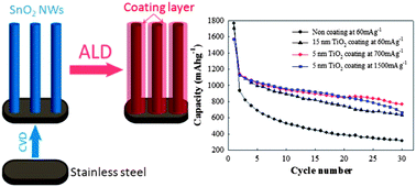
This paper reports the use of thin titania or alumina coatings on tin oxide nanowire arrays for high cyclability electrodes for lithium-ion batteries. We demonstrate that such coatings can significantly reduce irreversible capacity loss associated with the formation of a solid electrolyte interface and improve the capacity retention at high rates. Specifically, tin oxide nanowires grown on stainless steel substrates were conformally coated with thin films of either titania or alumina using atomic layer deposition and were tested as anodes in coin cells. Both titania and alumina coatings resulted in no initial capacity loss due to solid electrolyte interface formation in the first cycle. Tin oxide nanowire array electrodes coated with 5 nm thick titania layer and 1 nm thick alumina layer retained capacities of 767 and 725 mA h g−1 after 30 cycles using current density of 700 mA g−1. Both electrodes retained capacity around 664 mA h g−1 after 30 cycles using a current density of 1500 mA g−1, respectively. The results indicate that thin coatings acted as mechanical shells preserving the electrode nanostructure morphology necessary for high capacity retention. The study also showed that within the first two cycles, tin migrates out forming nanoclusters on the surface of nanowires due to both stress enhanced diffusion and the Kirkendall effect. The presence of tin nanoclusters on the surface of protective layers further enhances high rate capability.
Introduction

Tin-based materials have attracted a great deal of attention for anodes in lithium-ion batteries (LIBs) due to their high theoretical capacities of 781 mA h g−1, 991 mA h g−1 for the cases of SnO2 and Sn, respectively.1,2 In particular, tin oxide (SnO2) has been considered as a promising candidate that can substitute for commonly used graphite electrodes. However, SnO2 based anodes suffer from two major drawbacks: (i) capacity fading due to their volume expansion during cycling3,4 leading to mechanical degradation, pulverization of electrode materials with chemical degradation and (ii) initial capacity loss resulting from the formation of insulating Li2O,5 and a solid electrolyte interface (SEI).6

Several approaches have focused on improving the capacity retention by lowering the pulverization of SnO2 and mechanical degradation due to volume expansion. For example, Ding et al.7 reported that a capacity of 773.7 mA h g−1 could be retained after 100 cycles by using a nanocomposite SnO2–Se thin film. Similarly, a study by Yu et al. has shown that a novel composite of Li2O–CuO–SnO2 exhibited a capacity of 1158 mA h g−1 at 0.5 C and 525 mA h g−1 at 8 C after 100 cycles.8 Xia et al. have reported that composites of SnO2 nanoparticles and carbon nanofibers showed a capacity retention of 383 mA h g−1 after 30 cycles at the current density of 100 mA g−1.9 Mei et al.10 have shown a reversible capacity of 810 mA h g−1 after 50 cycles for the hybrid electrode consisting of porous Co–SnO2 spheres.

Nanowire morphology offers conducting pathways and short length scales for lithium ion diffusion. However for SnO2 nanowires (SnO2 NWs), the chemical degradation through Li2O + Sn formation during lithium alloying/de-alloying will result in quick degradation of morphology within the first five cycles leading to severe capacity degradation to around 300 mA h g−1.11 Several approaches have been reported in the literature to improve capacity retention of SnO2 NW-based anodes. For instance, Kim et al.12 have synthesized coaxial SnO2–In2O3 heterostructured nanowires and shown a high capacity retention of 700 mA h g−1 after 10 cycles due to high electronic conductivity of heterostructured nanowires by incorporation of Sn into In2O3 shell. In another study, a binder-free SnO2 NW, grown directly on current collector, has been shown to deliver a capacity of 600 mA h g−1 after 30 cycles at the current density of 782 mA g−1 (1 C), but using only a small voltage range of 0.0–1.2 V.13 Recently, Zhang et al.14 has shown that an increase of 3–4 orders of magnitude in conductivity of SnO2 NWs could be obtained by coating with a layer of carbon which helped with rate performance. On the other hand, Sn nanocluster covering SnO2 NWs have exhibited an exceptional capacity of 814 mA h g−1 after 100 cycles.15 However, none of these approaches have addressed the reduction of the irreversible capacity losses that results in severe capacity fading in the first few cycles.

More recently, there has been increased interest in using protective layers on active materials to reduce the irreversible capacity loss. A key requirement for a good protective coating is to have poor electrical conductivity and high Li ion conductivity. These approaches have focused on using wet chemical methods to form titania-based protective coatings on SnO2 particles,16 SnO2 nanofibers17 and SnO2 nanotubes.18 These methods, however, require multiple complex steps for making the protective coating and often result in incomplete coverage of the tin oxide leading to a pin hole in the protective layer.16 Recently, atomic layer deposition (ALD) has been introduced as an effective technique for depositing uniform layers on nanostructures.19 Although the use of titania-based materials as protective coatings has been shown to improve electrochemical performance, several fundamental questions as to how these materials act as a protective coating, mechanism of SEI formation and factors determining the lowering of irreversible capacity loss in the first cycle, still need to be addressed and understood.

However, there have been few studies performed to understand the stability of thin coatings and their influence on the morphological stability of nanowires. In order to gain fundamental insight, binder-free SnO2 NW arrays coated with thin protective layers are studied here in this work.

Experimental section

SnO2 NW arrays are synthesized on a variety of substrates including stainless steel (SS) (Alfa Aesar) using a reactive vapor transport of tin in lean oxygen conditions (5 sccm O2 and 350 sccm H2) at 1 Torr. The detailed experiment procedure has been described earlier.20 Briefly, the source material is placed in an alumina coated tungsten boat heater. The Sn metal vapor gets oxidized on the substrate and leads to the growth of vertical nanowire arrays in a self-catalyzed fashion. The as-synthesized SnO2 NWs on SS are coated with titania or alumina using an ALD (Cambridge Nanotech) at 250 °C with titanium tetra isopropoxide or trimethyl aluminum, respectively, and water as precursors. In each cycle, a pulse duration of 0.2 seconds, and nitrogen flow rate of 20 sccm are used. The samples are characterized using a scanning electron microscope (FEI Nova 600), X-ray diffraction (Bruker D8 Discovery with Cu Kα radiation), and a transmission electron microscope (Tecnai F20 FEI TEM operating at 200 kV).

The electrochemical measurements are performed using CR2032 coin-type cells assembled in a dry argon-filled glove box. The test cell consists of a working anode electrode of titania coated SnO2 NWs and a counter electrode of lithium metal. The electrodes are separated by two pieces of glass fiber filter (ADVANTEC GB-100R. Toyo Rishi CO., Japan). The electrolyte solution used is 1 M LiPF6–ethylene carbonate (EC)[thin space (1/6-em)]:[thin space (1/6-em)]dimethyl carbonate (DMC) (1[thin space (1/6-em)]:[thin space (1/6-em)]2 by volume). No binders are used. The charge–discharge measurements are carried out using a battery tester (16 channel Arbin Instruments, USA).

Results and discussion

SnO2 NW arrays are synthesized directly on the SS substrate without using any catalyst. As shown in Fig. 1, the SnO2 NWs are ∼300 to 1000 nm in diameter and about tens of microns in length. The as-grown SnO2 NW arrays on steel substrate are coated with thin layers of either titania or alumina. The TEM image in Fig. 1 shows the atomic layer deposited 15 nm thick titania on SnO2 nanowires. The thickness of titania or alumina coating is varied from 15 nm to 1 nm in this study.
image file: c3ra46003g-f1.tif
Fig. 1 SEM and TEM (inset) images of titania-coated SnO2 NWs before cycling.

The lithium intercalation–de-intercalation with tin oxide is expected to proceed according to the following two reactions.21 The first reaction is typically considered as irreversible and the second one is reversible.

 
SnO2 + 4Li+ + 4e → 2Li2O + Sn (1)
 
Sn + xLi+ + xe ↔ LixSn (0 ≤ x ≤ 4.4) (2)

Cyclic voltammetry (CV) of pure tin oxide nanowire powders mixed with binders shows peaks corresponding to the above two reactions. Analysis of the CV of tin oxide nanowires coated with protective layers is shown in Fig. 2a. In addition to alloying peaks at ∼0.1–0.3 V (ref. 22) and dealloying peaks at ∼0.5–0.6 V (ref. 23) seen for pure tin oxide NWs, a sharp cathodic peak at 0.68 V corresponding to the irreversible reduction of tin oxide to tin is observed.24 The peak at 0.68 V is significantly reduced in the subsequent cycles due to the irreversibility of reaction (1). In comparison with the CV of pure SnO2 NWs (Fig. S1, ESI), the peak position is shifted from 0.8 V to 0.68 V, and could be due to the presence of coating layers. The second and the subsequent cycles show a broad cathodic peak at 0.85 V that could be assigned to the formation of an SEI layer.22 Additional anodic peaks at 0.25 V, 0.75 V and 0.85 V could be due to delithiation of the LixSn alloy formed by a tin cluster coming out on the surface of coatings.20 These peaks have not been observed in the CV of pure tin oxide nanowires, indicating that Sn clusters on the surface are formed only when the protective coatings are used.


image file: c3ra46003g-f2.tif
Fig. 2 (a) Cyclic voltammetry of titania-coated SnO2 NWs at the voltage range of 2.2–0.005 V using scan speed of 5 mV min−1. (b) Charge–discharge capacity of pure SnO2 NWs and titania-coated SnO2 NWs at the voltage range of 2.2–0.005 V using a current density of 60 mA g−1; (c) comparison of capacity vs. cycle number of SnO2 NWs and titania-coated SnO2 NWs at currents of 60, 700, and 1500 mA g−1; (d) comparison of capacity vs. cycle number of SnO2 NWs and alumina-coated SnO2 NWs at currents of 60, 700, and 1500 mA g−1.

Fig. 2b shows a comparison of 1st cycle charge–discharge capacity of pure SnO2 NWs and titania-coated SnO2 NWs in the voltage range of 0.005–2.2 V, using a current density of 60 mA g−1. The initial discharge capacity of titania-coated SnO2 NWs is 1705 mA h g−1 which is twice theoretical capacity of bulk SnO2. The high initial discharge capacity is believed to be due to the reduction of tin oxide to tin and the intercalation of Li into SnO2 and complete access to all of the tin for forming LixSn alloys as depicted by the plateau at 0.9 V. The first cycle coulombic efficiency is 72.6%, which is much higher than that of our pure SnO2 NWs of 49.5% (Table S1, ESI), and also much higher than 60% previously reported for a similar structure of titania-coated SnO2 hollow nanoparticles.16 To the best of our knowledge, this is the highest and first of its kind value reported for binder-free SnO2-based electrodes. The initial capacity loss due to SEI formation can be calculated based on the overall capacity loss and the capacity loss due to tin oxide reduction.16 Accordingly, the initial capacity loss due to SEI formation for pure SnO2 NWs is calculated to be 448 mA h g−1 while the titania- and alumina-coated SnO2 NW array electrodes show no initial capacity loss due to SEI formation (Table S1, ESI). The previous attempt to use lithium titanate as a protective coating identified the incomplete coverage as one of the major challenges in reducing irreversible capacity loss.16 In our case, the full coverage suppressed the formation of SEI in the first cycle. Both titania and alumina coatings minimize the irreversible capacity loss and account for the observed increase in the columbic efficiency when compared to uncoated SnO2 NWs. A charge–discharge measurement of titania-coated SnO2 NWs at 1.0–3.0 V (Fig. S2, ESI) shows a small capacity of 6 mA h g−1. This capacity of 6 mA h g−1 comes from titania layer which means that all of the observed capacities are mainly from SnO2 NWs.

Fig. 2c shows the comparison of capacity vs. cycle number of SnO2 NWs and titania coated SnO2 NWs at current density of 60, 700, and 1500 mA g−1. The pure SnO2 electrode exhibits an initial discharge capacity of 1680 mA h g−1 at a current density of 60 mA g−1 but fades quickly to 316 mA h g−1 after 30 cycles. Coating of SnO2 NWs with 15 nm titania resulted in a similar initial capacity as the one measured for uncoated SnO2 NWs (1705 mA h g−1). However, a significant increase of capacity retention of 634 mA h g−1 after 30 cycles at the same current of 60 mA g−1 is observed. Even a thinner titania layer of 5 nm showed higher capacity retention of 767 and 664 mA h g−1 at the higher current density of 700 and 1500 mA g−1, respectively. Previous studies have shown that amorphous titania has a higher lithium diffusivity coefficient, and a higher rate capacity than those of anatase titania.25,26 The use of amorphous titania in our study can result in formation of intermediate phase of LixTiO2 which has been shown to be a good lithium ion conductor.25 All of this supports the fact that coating titania on SnO2 enables the high rate capacity of titania-coated SnO2 NW electrodes. Thus, the presence of a uniformly coated titania layer is one of the reasons why the high capacity retention is obtained at very high current density. Another reported experiment with alumina as a coating layer has shown good performance on cathode materials.19 In our study, the 1 nm thick alumina-coated SnO2 NW electrode exhibited a high capacity retention of 725 and 663 mA h g−1 at the current density of 700 and 1500 mA g−1 after 30 cycles, respectively (Fig. 2d). During cycling, there may be formation of Li2O–Al2O3 glass which has high ionic conductivity and low electrical conductivity.27 The Li2O–Al2O3 glass could serve as a stable solid electrolyte for fast lithium ion diffusion.28 This is also in agreement with a previous report that lithium ions could transport through the electrically insulating layer of alumina and improve the rate capacity.29

The lack of SEI formation during the first cycle with titania or alumina coated SnO2 NWs can be explained by the band edge diagram of SnO2 and coated layers. See Fig. 3, the band edge off-set prevents the electron migration from tin oxide to coatings and then to the electrolyte. Further poor electrical conductivity and poor electron transport properties of amorphous titania inhibit electron transfer to the electrolyte, mitigating SEI formation in the first cycle.30 Moreover, the band edge off-set created by the alumina layer is even larger. No electron migration from tin oxide to the electrolyte through alumina is expected as well. Thus, there is no SEI formation in the first cycle. The observation of SEI formation in the second cycle is surprising and will be explained later.


image file: c3ra46003g-f3.tif
Fig. 3 Energy band diagram of SnO2 and Al2O3 (a), TiO2 (b) with respect to the electrochemical scale. Ev, Ec, and Eg represent valence band maxima, conduction band minima and bandgap, respectively.

Fig. 4a shows the XRD patterns of pure SnO2 NWs, and titania coated SnO2 NWs. All of the peaks of SnO2 NWs are assigned to pure SnO2 single-phase structure, while titania coated SnO2 NWs show the same phase with low intensity peaks. No peaks corresponding to titania or alumina were observed from tin oxide nanowires coated with thin layers indicating the amorphous nature of the coatings. The TEM image in Fig. 1 also corroborates the formation of an amorphous layer of titania. The XRD patterns also shows that SnO2 NWs are completely reduced to Sn after cycling when using titania-coated SnO2 NWs. This is completely expected and similar to other studies using a SnO2 electrode.11,12 However, in our case the nanowire morphology is retained after cycling while the other studies showed that the SnO2 NW is destroyed while cycling. The SEM and TEM images of a typical titania-coated SnO2 NW after cycling for 100 cycles are shown in Fig. 4b. It is clear that titania- or alumina-coated SnO2 NW morphology is maintained after 100 charge–discharge cycles. This is due to the presence of a titania or alumina layer, which acts as a mechanical protective shield against pulverization during volume expansion, while still allowing lithium ions to diffuse through to maintain cycling process. This further explains the high capacity retention at a very high current density of 1500 mA g−1. The presence of a titania layer also helps to scavenge HF produced by the reaction of the trace amounts of water and LiPF6 in the electrolyte.31 However, our observation reveals that all samples experienced severe delamination after 30 cycles with slow fading after 17 cycles (Fig. S3, ESI). The columbic efficiency is 87% for the 1st cycle, increases to 97% at the 3rd cycle and remains up to 17th cycle, then drops down to 89% at the 30th cycle. The decrease of columbic efficiency is attributed to slow delamination from the 17th cycle to 30 cycles and then rapid delamination from 30 cycles to 100 cycles. As shown in the SEM images of electrodes after 100 cycles, the morphology is completely retained while showing complete delamination from the substrate. Hence, the binder or some other coating is necessary to avoid the delamination.


image file: c3ra46003g-f4.tif
Fig. 4 The XRD pattern showing no peak of titania due to the amorphous phase, the tin oxides were completely reduced to tin after cycling (a), SEM and TEM (inset) images of titania-coated SnO2 NWs after 100 cycles showing the original morphology (b).

In addition, energy dispersive X-ray spectroscopy (EDS) data of titania or alumina coated SnO2 NW electrodes after cycling revealed the presence of a small tin cluster on the outer surface of the SnO2 NW (Fig. S4, ESI). The observation of the Sn nanocluster is much less when titania coated SnO2 NWs are cycled between 1.0 to 3.0 V allowing lithium intercalation into titania and not into SnO2 (Fig. S5, ESI). The results suggest that the migration of tin out to the surface of the coating layer happened when the lithium ion intercalates into tin oxide. Similar results are obtained with thin alumina coated SnO2 NW electrodes.

The diffusion or migration of tin through the coating is interesting and needs to be understood further. Much of the diffusion or migration seems to happen in the first few cycles. As these coatings (both titania and alumina) are rigid, they thus develop stress during volume expansion experienced with the lithium intercalation process. For a thin wall titania tube with external and internal nominal diameters of ∼75 nm and ∼65 nm, Shokuhfar et al.32 have reported the maximum axial strain of 5%. Assuming that the radial strain is the same as the axial strain (it should actually be smaller33), the total volume expansion of a titania shell of 15 nm wall thickness, 300 nm inner diameter, can be calculated to be 115.7% with 5% radial and 5% axial elongation. This value is independent of wall thickness and inner diameter of the titania nanotube. This confirms that the titania layer suppresses the radial expansion, and probably axial expansion as well, since the volume expansion of tin oxide is 240% with 45% radial and 60% axial elongation.34 Wang et al.35 have shown that the LixSn ball diffused out to the SnO2 NW surface upon the 1st charging cycle. In another study, Zhang et al.36 have reported that tin could precipitate out on the nanowire surface due to strain gradient and breaking of the coating layer of LiAlSiOx. In our study, tin nanoclusters come out on the surface of titania or alumina coating layer even when there are no apparent cracks in the coating layer when examined in TEM. Tin nanoclusters seem to diffuse through the titania layer without breaking it. Atomic scale tin could be produced during the reduction of tin oxide to tin or delithiation of LixSn alloy. Tin atoms diffuse out on the surface to reduce stresses, tin crystals nucleate and coalesce to form tin nanoclusters on the nanowire surface (Fig. 5). This phenomenon has been widely observed for tin whisker growth in many other reports.36,37 In contrast with a recent report on carbon coating on SnO2 NWs,14 a similar volume confinement has been seen with carbon coating on SnO2 NWs but no tin nanocluster on the nanowire surface was observed. This may be due to the different properties of coatings such as electronic conductivity, and tin and lithium diffusion rates. During cycling, the void accumulated inside the nanowire due to de-intercalation leads to the formation of a hollow nanowire structure of SnO2 (Fig. S6, ESI). Another explanation for the hollow structure of SnO2 after cycling is due to the difference in the diffusion coefficients of lithium ions and tin atoms through coating layers of titania or alumina, and Li2O + LixSn + Sn matrix. The Kirkendall effect is used to describe the formation of hollow structures, which involves the diffusion of two species with different diffusion rates. The outward diffusion of Sn may be faster than the inward diffusion of lithium ions. Thus, voids may be formed due to the transport of tin to the outer surface of the protective coatings. With time, these voids diffuse toward the center to form a hollow core, as seen in Fig. S6 (ESI), resulting in a Kirkendall effect.38


image file: c3ra46003g-f5.tif
Fig. 5 HR-TEM images of tin nanocluster evolution on the surface of the titania coating layer: tin started squeezing out (a) and (b); coalescing to form a tin nanocluster (c); tin nanoclusters on the nanowire surface (d).

The presence of tin nanoclusters on the outer surface of SnO2 NWs promotes the electronic conductivity of the electrodes which also explains the high capacity retention at very high current density.23 The tin nanocluster formation during the 1st cycle (Fig. S7, ESI) also triggers SEI formation from the 2nd cycle and remains up to 10th cycle as shown in Fig. 2a. This is consistent with what is observed in the cyclic voltammetry results shown in Fig. 2. Fig. S8 (ESI) shows the SEM image of 5 nm titania, and 1 nm alumina-coated SnO2 NWs after cycling for 52 cycles. Interestingly, the NW morphology is still maintained, with a wire-like morphology held by Li2O matrix with Sn particles, but the coating seems to dissolve in ethanol during sample preparation. These results suggest that even 1 nm thin coatings could protect the SnO2 NW morphology. The Young's and bulk moduli of titania and alumina (Table S2, ESI) suggest that alumina coating will be more rigid exerting more stress during lithium intercalation. The TEM-based EDS analysis of 1 nm thick alumina-coated SnO2 NWs suggests the presence of Sn particles and some carbon, fluorine, and phosphor materials which are believed to come from the decomposition of the electrolyte (Fig. S9, ESI). These materials are reported to be a stable SEI layer which help to increase the rate capacity.29

Conclusions

In summary, titania and alumina coatings have been investigated on SnO2 NWs without using any binders. Ultra-thin layers as thin as 1 nm stabilized the one-dimensional morphology of SnO2 nanowires and allowed for high capacity retention after 30 cycles at high rates (over 767 mA h g−1 at 1 C and 664 mA h g−1 at 2 C). No initial capacity loss due to SEI formation was found which increased the reversible capacity retention. Interestingly, both titania- and alumina-coated tin oxide nanowire arrays exhibited tin migration through the coatings to form tin nanoclusters. The compressive stress build-up during lithium intercalation and the enhanced diffusion of tin during lithium de-intercalation allowed for migration of tin to the outside of coatings. The knowledge of the stability of ultra-thin coatings during lithium intercalation–de-intercalation is important for many material systems. The results obtained with tin should be applicable to other high capacity materials such as silicon.

Acknowledgements

The authors gratefully acknowledge the Conn Center for Renewable Energy Research for facilities and access to characterization equipment and partial support from KY DOE-EPSCoR (DE-FG02-07ER46375). TQN also acknowledges the financial support from a Grosscurth Fellowship.

Notes and references

  1. G. Derrien, J. Hassoun, S. Panero and B. Scrosati, Adv. Mater., 2007, 19, 2336–2340 CrossRef CAS.
  2. M. Winter and J. O. Besenhard, Electrochim. Acta, 1999, 45, 31–50 CrossRef CAS.
  3. M. Wachtler, M. Winter and J. O. Besenhard, J. Power Sources, 2002, 105, 151–160 CrossRef CAS.
  4. B. A. Boukamp, G. C. Lesh and R. A. Huggins, J. Electrochem. Soc., 1981, 128, 725–729 CrossRef CAS PubMed.
  5. N. Li, C. R. Martin and B. Scrosati, Electrochem. Solid-State Lett., 2000, 3, 316–318 CrossRef CAS PubMed.
  6. J.-S. Bridel, S. Grugeon, S. Laruelle, J. Hassoun, P. Reale, B. Scrosati and J.-M. Tarascon, J. Power Sources, 2010, 195, 2036–2043 CrossRef CAS PubMed.
  7. X.-L. Ding, Q. Sun, F. Lu and Z.-W. Fu, J. Power Sources, 2012, 216, 117–123 CrossRef CAS PubMed.
  8. Y. Yu, C.-H. Chen and Y. Shi, Adv. Mater., 2007, 19, 993–997 CrossRef CAS.
  9. W. Xia, Y. Wang, Y. Luo, J. Li, Y. Fang, L. Gu, J. Peng and J. Sha, J. Power Sources, 2012, 217, 351–357 CrossRef CAS PubMed.
  10. L. Mei, C. Li, B. Qu, M. Zhang, C. Xu, D. Lei, Y. Chen, Z. Xu, L. Chen, Q. Li and T. Wang, Nanoscale, 2012, 4, 5731–5737 RSC.
  11. M.-S. Park, G.-X. Wang, Y.-M. Kang, D. Wexler, S.-X. Dou and H.-K. Liu, Angew. Chem., 2007, 119, 764–767 CrossRef.
  12. D.-W. Kim, I.-S. Hwang, S. J. Kwon, H.-Y. Kang, K.-S. Park, Y.-J. Choi, K.-J. Choi and J.-G. Park, Nano Lett., 2007, 7, 3041–3045 CrossRef CAS PubMed.
  13. Y.-D. Ko, J.-G. Kang, J.-G. Park, S. Lee and D.-W. Kim, Nanotechnology, 2009, 20, 455701 CrossRef PubMed.
  14. L. Q. Zhang, X. H. Liu, Y. Liu, S. Huang, T. Zhu, L. Gui, S. X. Mao, Z. Z. Ye, C. M. Wang, J. P. Sullivan and J. Y. Huang, ACS Nano, 2011, 5, 4800–4809 CrossRef CAS PubMed.
  15. P. Meduri, C. Pendyala, V. Kumar, G. U. Sumanasekera and M. K. Sunkara, Nano Lett., 2009, 9, 612–616 CrossRef CAS PubMed.
  16. G. Ji, Y. Ma, B. Ding and J. Y. Lee, Chem. Mater., 2012, 24, 3329–3334 CrossRef CAS.
  17. H. Park, T. Song, H. Han, A. Devadoss, J. Yuh, C. Choi and U. Paik, Electrochem. Commun., 2012, 22, 81–84 CrossRef CAS PubMed.
  18. X. Wu, S. Zhang, L. Wang, Z. Du, H. Fang, Y. Ling and Z. Huang, J. Mater. Chem., 2012, 22, 11151–11158 RSC.
  19. Y. S. Jung, A. S. Cavanagh, L. A. Riley, S.-H. Kang, A. C. Dillon, M. D. Groner, S. M. George and S.-H. Lee, Adv. Mater., 2010, 22, 2172–2176 CrossRef CAS PubMed.
  20. P. Meduri, E. Clark, E. Dayalan, G. U. Sumanasekera and M. K. Sunkara, Energy Environ. Sci., 2011, 4, 1695–1699 CAS.
  21. R. Demir-Cakan, Y.-S. Hu, M. Antonietti, J. Maier and M.-M. Titirici, Chem. Mater., 2008, 20, 1227–1229 CrossRef CAS.
  22. D. Aurbach, A. Nimberger, B. Markovsky, E. Levi, E. Sominski and A. Gedanken, Chem. Mater., 2002, 14, 4155–4163 CrossRef CAS.
  23. N. Li and C. R. Martin, J. Electrochem. Soc., 2001, 148, A164–A170 CrossRef CAS PubMed.
  24. I. A. Courtney and J. R. Dahn, J. Electrochem. Soc., 1997, 144, 2045–2052 CrossRef CAS PubMed.
  25. H. Yildirim, J. Greeley and S. K. R. S. Sankaranarayanan, J. Phys. Chem. C, 2011, 115, 15661–15673 CAS.
  26. H.-T. Fang, M. Liu, D.-W. Wang, T. Sun, D.-S. Guan, F. Li, J. Zhou, T.-K. Sham and H.-M. Cheng, Nanotechnology, 2009, 20, 225701 CrossRef PubMed.
  27. A. M. Glass and K. Nassau, J. Appl. Phys., 1980, 51, 3756–3761 CrossRef CAS PubMed.
  28. Y. Liu, N. S. Hudak, D. L. Huber, S. J. Limmer, J. P. Sullivan and J. Y. Huang, Nano Lett., 2011, 11, 4188–4194 CrossRef CAS PubMed.
  29. F.-F. Cao, J.-W. Deng, S. Xin, H.-X. Ji, O. G. Schmidt, L.-J. Wan and Y.-G. Guo, Adv. Mater., 2011, 23, 4415–4420 CrossRef CAS PubMed.
  30. H. Nishikiori, R. A. Setiawan, K. Miyamoto, G. Sukmono, Y. Uesugi, K. Teshima and T. Fujii, RSC Adv., 2012, 2, 4258–4267 RSC.
  31. H.-M. Cheng, F.-M. Wang, J. P. Chu, R. Santhanam, J. Rick and S.-C. Lo, J. Phys. Chem. C, 2012, 116, 7629–7637 CAS.
  32. T. Shokuhfar, G. K. Arumugam, P. A. Heiden, R. S. Yassar and C. Friedrich, ACS Nano, 2009, 3, 3098–3102 CrossRef CAS PubMed.
  33. S. Reich, C. Thomsen and P. Ordejón, Phys. Rev. B: Condens. Matter, 2002, 65, 153407 CrossRef.
  34. J. Y. Huang, L. Zhong, C. M. Wang, J. P. Sullivan, W. Xu, L. Q. Zhang, S. X. Mao, N. S. Hudak, X. H. Liu, A. Subramanian, H. Fan, L. Qi, A. Kushima and J. Li, Science, 2010, 330, 1515–1520 CrossRef CAS PubMed.
  35. C.-M. Wang, W. Xu, J. Liu, J.-G. Zhang, L. V. Saraf, B. W. Arey, D. Choi, Z.-G. Yang, J. Xiao, S. Thevuthasan and D. R. Baer, Nano Lett., 2011, 11, 1874–1880 CrossRef CAS PubMed.
  36. L. Q. Zhang, X. H. Liu, Y.-C. Perng, J. Cho, J. P. Chang, S. X. Mao, Z. Z. Ye and J. Y. Huang, Micron, 2012, 43, 1127–1133 CrossRef CAS PubMed.
  37. K. N. Tu, Phys. Rev. B: Condens. Matter, 1994, 49, 2030–2034 CrossRef CAS.
  38. H. J. Fan, U. Gösele and M. Zacharias, Small, 2007, 3, 1660–1671 CrossRef CAS PubMed.

Footnote

Electronic supplementary information (ESI) available. See DOI: 10.1039/c3ra46003g

This journal is © The Royal Society of Chemistry 2014