Design and evaluation of a mixed monolayer consisting of alkylsilane and novel crown-type molecules
Li Chena,
Baoping Yanga and
Junyan Zhang*b
aCollege of Petrochemical Technology, Lanzhou University of Technology, Lanzhou 730050, China. E-mail: chenli1981@163.com; Fax: +86 931 7823127; Tel: +86 931 7823127
bState Key Laboratory of Solid Lubrication, Lanzhou Institute of Chemical Physics, Chinese Academy of Sciences, Lanzhou 730000, China. E-mail: zhangjunyan@licp.cas.cn; Fax: +86 931 4968295; Tel: +86 931 4968295
First published on 11th December 2013
Abstract
A mixed film composed of crown-type molecule hexachlorotribenzotriquinacene (HCTQ) and 3-[2-(2-aminoethylamino)ethylamino]propyl-trimethoxysilane (TA), together with their single-component films, were formed on hydroxylated silicon substrates by self-assembly. The formation and surface properties of the films were characterized by means of ellipsometry, contact angle measurement, attenuated total reflectance Fourier transform infrared (ATR-FTIR) spectrometry, multi-functional X-ray photoelectron spectra (XPS), and atomic force microscopy (AFM). The nano- and micro-tribological behavior of the films was evaluated by AFM and ball-on-plate tribometer, respectively. The results show that the mixed film exhibits enhanced nano- and micro-tribological properties as compared to the single-component films. This is attributed to the synergic effect between the load-carrying capacity of the crown-type molecule and the friction-reducing contribution of the straight chain molecule. The multiple functional groups and rigid aromatic backbone in the crown-type molecule enhance the stability and the anti-wear property of the mixed film, while the flexible alkylsilane serves as lubricant for reducing the friction. In addition, the two-step assembly of the crown-type molecule and alkylsilane can form more densely packed and ordered mixed film, which is beneficial to improving the durability and anti-wear property.
1. Introduction
The evolution in miniaturized mechanical components and microelectronic components has brought about the exciting field of micro/nanoelectromechanical systems (MEMS/NEMS). As the dimensions of the components decrease, the surface forces such as adhesion, stiction, and friction become predominant factors,1–3 which have become significant technological barriers for the successful development of durable and reliable microdevices.4–6 Therefore, controlling physical and chemical properties of MEMS/NEMS surfaces is both scientifically significant and technologically important. The ideal lubricants for microdevices should possess the following properties: molecular thickness, chemically bonded to substrate surfaces, excellent durability and reliability, and insensitive to environment.7Self-assembled monolayers (SAMs) have attracted extensive interests in the fields of surface modification, chemical and biological sensors, wetting, and so on.6–11 The surface terminal groups of SAMs can be conveniently tailored to improve the properties of films. The influences of various substrates, head and tail groups, interfacial bond strength, and molecular chain length have been investigated by many researchers.12–18 Compared to single-component SAMs, mixed SAMs composed of organosilanes with different chain lengths and/or terminal functional groups can offer adjustable surfaces with different functionalities.19–23 However, the durability of mixed SAMs composed of alkylsilanes with different chain lengths is poor because of the inferior load-carrying capacity of flexible backbone. It is well known that the requirements for effective lubricants are strong adhesion to substrates, reduced friction, excellent load-carrying and anti-wear properties.24,25 Based on this knowledge, creating two-phase lubrication films which contain both load-carrying and friction-reducing phases is a promising approach.
In this study, a specially designed crown-type molecule with multiple functional groups and aromatic-rich structure was used. It is believed that multiple functional groups, which could form strong chemical bonds with substrates, can promote the stability of films. Moreover, aromatic backbone is more rigid than straight alkyl chain, so it will improve the load-carrying capacity of films.26–28 The stepwise assembly method29 was employed to fabricate mixed monolayer. That is, crown-type molecule was firstly deposited on silicon substrate to create vacant sites owing to the semi-spherical molecular structure.30 Then the alkylsilane with straight alkyl chain was introduced to the substrate area uncovered by the crown-type molecule. The constructed mixed film, which contains crown-type molecule with rigid backbone and alkylsilane with flexible backbone, is expected to possess improved load-carrying capacity and enhanced anti-wear property. The relationship between chemical composition, microstructure and tribological behavior of the as-prepared films was investigated, aiming at further optimizing the micro/nano-tribological behavior and developing thin film lubricants for MEMS/NEMS.
2. Experimental
2.1. Materials
The crown-type molecule hexachlorotribenzotriquinacene (designated as HCTQ, purity >97%) was provided by State Key Laboratory of Applied Organic Chemistry, College of Chemistry and Chemical Engineering in Lanzhou University, and the synthesis process was described elsewhere.31 3-[2-(2-Aminoethylamino)ethylamino]propyl-trimethoxysilane (designated as TA) (Aldrich, purity >95%) was used as received. The molecular structures are shown in Fig. 1. Toluene was treated with sodium thread to eliminate water using benzophenone as the indicator. p-Type polished single-crystal Si(100) wafers used as the substrates were obtained from Grinm Semiconductor Materials Co., Ltd. (Beijing, China). Ultrapure water (>18 MΩ) was used in this work.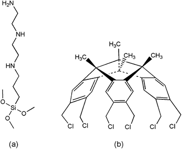 | ||
| Fig. 1 Chemical structures of (a) 3-[2-(2-aminoethylamino)ethylamino]propyl-trimethoxysilane and (b) hexachlorotribenzotriquinacene. | ||
2.2. Preparation of single- and mixed-component films
Silicon wafers with dimension of 10 mm × 15 mm were cleaned and hydroxylated in freshly Piranha solution (mixture of 7![[thin space (1/6-em)]](https://www.rsc.org/images/entities/char_2009.gif) :
:![[thin space (1/6-em)]](https://www.rsc.org/images/entities/char_2009.gif) 3 (v/v) 98% H2SO4 and 30% H2O2) at 90 °C for 40 min. After being rinsed copiously with deionized water and dried in a stream of nitrogen gas, the hydroxylated silicon wafers were exposed to a dehydrated toluene solution containing 2 mM HCTQ at 60 °C for 24 h. After being removed from the solution, they were ultrasonically cleaned in toluene and acetone for 5 min, respectively. Then they were washed with deionized water and dried under a flow of nitrogen gas. The film is designated as HCTQ film.
3 (v/v) 98% H2SO4 and 30% H2O2) at 90 °C for 40 min. After being rinsed copiously with deionized water and dried in a stream of nitrogen gas, the hydroxylated silicon wafers were exposed to a dehydrated toluene solution containing 2 mM HCTQ at 60 °C for 24 h. After being removed from the solution, they were ultrasonically cleaned in toluene and acetone for 5 min, respectively. Then they were washed with deionized water and dried under a flow of nitrogen gas. The film is designated as HCTQ film.
The hydroxylated silicon wafers were dipped into a fresh solution containing 5 mM TA for 4 h, using a mixture of acetone and ultrapure water (v/v = 5![[thin space (1/6-em)]](https://www.rsc.org/images/entities/char_2009.gif) :
:![[thin space (1/6-em)]](https://www.rsc.org/images/entities/char_2009.gif) 1) as the solvent. The wafers were removed from the solution and ultrasonically cleaned in toluene and acetone for 5 min, respectively. And then washed with deionized water and blown dry with nitrogen gas. The film is designated as TA film.
1) as the solvent. The wafers were removed from the solution and ultrasonically cleaned in toluene and acetone for 5 min, respectively. And then washed with deionized water and blown dry with nitrogen gas. The film is designated as TA film.
The mixed film was prepared via a simple two-step strategy. Firstly, the HCTQ film was prepared as mentioned above, and then the functionalized wafers were immersed in a fresh solution containing 5 mM TA for 4 h, using a mixture of acetone and ultrapure water (v/v = 5![[thin space (1/6-em)]](https://www.rsc.org/images/entities/char_2009.gif) :
:![[thin space (1/6-em)]](https://www.rsc.org/images/entities/char_2009.gif) 1) as the solvent. Then the specimens were removed from the solution, cleaned and dried as mentioned above. The target mixed film of HCTQ+TA thus formed on the hydroxylated silicon substrates.
1) as the solvent. Then the specimens were removed from the solution, cleaned and dried as mentioned above. The target mixed film of HCTQ+TA thus formed on the hydroxylated silicon substrates.
2.3. Characterization of the thin films
The thicknesses of films were evaluated on a L116-E ellipsometer (Gaertner, USA) equipped with a He–Ne laser (632.8 nm) at an incident angle of 50°. A refractive index of 1.46 was set for silicon oxide and 1.45 for organic films. Ten measurements were carried out at different positions to obtain average result for each specimen. A CA-A type contact angle meter (Kyowa Scientific Co. Ltd.) was employed to measure the static water contact angle. At least six measurements were carried out at different positions to obtain average result for each specimen. A Nanoscope IIIa Multimode atomic force microscope (AFM, Digital Instruments, UK) was employed to observe the film morphology in tapping mode. Attenuated total reflectance Fourier transform infrared (ATR-FTIR) spectra of films were recorded on a Bruker IFS 66V/S Fourier transformation infrared spectrometer, using a Harrick Scientific horizontal reflection Ge-attenuated total reflection accessory (GATR, incident angle of 65°). The spectra were collected for 64 scans with a resolution of 4 cm−1. The pressure in sample chamber and optical chamber was kept below 6.0 × 10⁻⁴ MPa to eliminate the interference of H2O and CO2. Chemical compositions and element chemical state on specimen surfaces were analyzed on a PHI-5702 X-ray photoelectron spectroscopy (XPS) at a pass energy of 29.4 eV, using Mg Kα radiation as excitation source. The spectra were calibrated using the binding energy of contaminated carbon (C 1s: 284.6 eV) as reference.2.4. Nano- and micro-tribological studies
The nano-tribological properties of films were studied using a SPA 300HV scanning probe microscope (SII NanoTechnology Inc. Japan). Commercially available V-shape Si3N4 cantilever was used with a torsional force constant of 0.1 N m−1 and a normal force constant of 2 N m−1. The output voltages were directly used as relative friction force. A series of friction–load curves were obtained from linear loading process, and each curve represented an average over six separate measurement locations. The adhesive forces were also determined at least six locations on each specimen. All of the experiments were carried out under ambient conditions of 20 °C and 40–50% relative humidity.Micro-tribological behaviors of films were studied on a UMT-2MT tribometer (CETR, USA) in a ball-on-plate reciprocating mode. Commercially available Si3N4 ball (3 mm in diameter) used as upper counterpart was stationary, while the lower specimen adhered on flat base kept reciprocating at a distance of 5 mm. The loads of 0.05 N and 0.1 N were applied for the measurements. The friction coefficient–time plots were recorded automatically, and more than three repeated measurements were performed. All tests were carried out at 20 °C and a relative humidity of 40–50%.
3. Results and discussion
3.1. Characterization of the thin films
The mixed film of HCTQ+TA was constructed on silicon substrate by a simple two-step method. As illustrated in Fig. 2, firstly, HCTQ was introduced onto the silicon wafer, and then TA molecule was deposited from a diluted solution to obtain the mixed film. Optical ellipsometry was applied as a convenient and simple means to determine the average thickness of the thin films. The thickness of HCTQ film is about 1.0 nm, which is in agreement with the theoretical prediction (1.1 nm). It can be deduced that HCTQ molecule has been assembled on silicon substrate and the HCTQ thin film is well organized. After being dipped into TA solution for 4 h, TA molecule was deposited and the mixed film of HCTQ+TA was formed. The thickness of the mixed film is 1.4 nm, and the increased thickness is attributed to the deposition of TA molecule. The thickness of the single-component TA film is about 1.6 nm.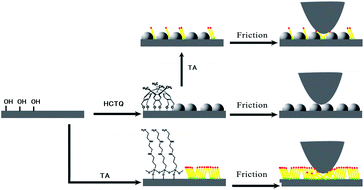 | ||
| Fig. 2 Schematic drawing of the constructing process and frictional mechanism of TA film, HCTQ film and HCTQ+TA mixed film. The illustration is not drawn to scale. | ||
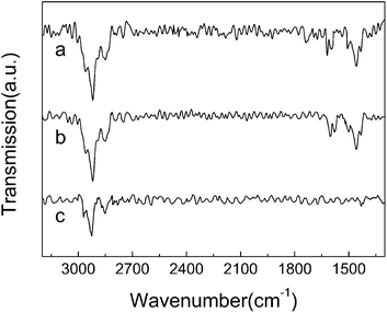
ATR-FTIR spectra of the thin films were collected, as shown in Fig. 3. For HCTQ film (Fig. 3a), the asymmetric and symmetric methylene vibrations are observed at 2920 and 2848 cm−1, respectively. The peaks at 1619 cm−1, 1594 cm−1, 1506 cm−1 and 1458 cm−1 are assigned to the skeleton vibration of benzene ring. For HCTQ+TA film (Fig. 3b), the vibrational signatures of methylene respectively appear at 2920 and 2848 cm−1. The characteristic absorption peaks of benzene ring are observed at 1602 cm−1, 1578 cm−1, 1500 cm−1 and 1458 cm−1, respectively. The vibration of N–H bond could not be seen in the spectrum owing to the weak signal. For comparison, the ATR-FTIR spectrum of TA film was also collected (Fig. 3c). Only the C–H stretching mode can be observed at 2925 cm−1 and 2851 cm−1 because the strength of N–H vibrational mode is quite weak. According to the previous reports,23,32 the asymmetric and symmetric methylene vibrations are observed in the range of 2915–2918 cm−1 and 2846–2850 cm−1 for all-trans extended ordered chain, and ∼2928 cm−1 and ∼2856 cm−1 for liquidlike disordered chains. From the locations of the peaks, we can see that the TA film is not densely packed.
In order to further characterize the chemisorption of TA molecule onto silicon substrate in HCTQ+TA mixed film, XPS analyses of HCTQ film and HCTQ+TA film were carried out, and the peak of nitrogen (N 1s) in mixed film was focused in the study of XPS spectra. As shown in Fig. 4a, the peaks of carbon (C 1s), oxygen (O 1s) and silicon (Si 2p) are found in the full scan survey spectrum of HCTQ film. Appearance of nitrogen (N 1s) in the full scan survey spectrum of HCTQ+TA mixed film, as shown in Fig. 4b, indicates that TA molecule is assembled successfully in the mixed film at the second self-assembly process. The fine spectrum of N 1s region of mixed film (Fig. 4c) shows an asymmetric broad band, which could be fitted by three peaks. The peak with a binding energy of 401.5 eV could be assigned to the protonation of some amino groups. The peaks at 400.6 eV and 399.4 eV could be ascribed to the hydrogen bonded and free NH2 groups, respectively.33–35 By comparing the intensities of the high resolution N 1s spectrum for the pure TA film and HCTQ+TA mixed film, the coverage of the TA molecule in the mixed system could be obtained. The molar ratio of HCTQ to TA is about 2![[thin space (1/6-em)]](https://www.rsc.org/images/entities/char_2009.gif) :
:![[thin space (1/6-em)]](https://www.rsc.org/images/entities/char_2009.gif) 1.
1.
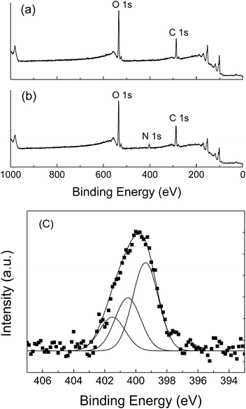 | ||
| Fig. 4 XPS spectra of (a) full scan survey spectrum of HCTQ film, (b) full scan survey spectrum of HCTQ+TA mixed film, and (c) fine spectrum of N 1s in mixed film. | ||
To obtain the microstructure information of the thin films, the surface morphologies of the prepared films were obtained by AFM. As shown in Fig. 5a and b, the surfaces of HCTQ film and HCTQ+TA mixed film are very smooth with root-mean-square (RMS) microroughness of 0.19 nm and 0. 21 nm over a scanning range of 1 μm × 1 μm, respectively. TA film exhibits some aggregation and the surface topography displays a relatively large RMS roughness of 0.27 nm (Fig. 5c).
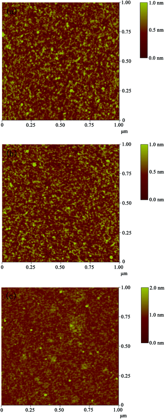 | ||
| Fig. 5 AFM images of various surfaces over a scanning range of 1 μm × 1 μm: (a) HCTQ film, (b) HCTQ+TA mixed film, and (c) TA film. | ||
3.2. Nanotribological behavior of the thin films
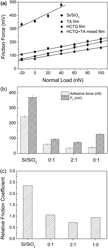
The stiction has been a major failure mode for MEMS/NEMS since the adhesion between contact interfaces becomes dominant at micro or nanoscale.36 To evaluate the anti-stiction property of the prepared films, the adhesive forces between AFM tip and thin film surfaces are measured. As shown in Fig. 6, the strong adhesion of 244 nN is observed on the surface of hydroxylated silicon wafer. This is because that the hydroxyl terminus is notorious for having high adhesive force, and the water contact angle of hydroxylated silicon wafer is less than 5°. After constructing thin films, the adhesive force decreased dramatically. The adhesion between contact interfaces is produced under the combined action of van der Waals, capillary, electrostatic and chemical bonding. When a hydrophilic film is introduced at the contact interface, the adhesive force is mainly dominated by capillary. The adhesive force can be reduced obviously with increasing the hydrophobicity of the surface. Many researchers have found that modifying the surfaces with long alkyl chain molecules can decrease the interfacial energy and the capillary force between AFM tip and surfaces,37–40 so the surfaces modified with nonpolarized groups exhibit lower adhesive force. The water contact angle of TA film is 40°, because the polarized amino groups possess high surface energy. So TA film exhibits the highest adhesive force among these thin films. For HCTQ film, the contact angle is 82° because of the semi-spherical molecular structure and the vacant sites on silicon surface where no adsorbed HCTQ molecule. Backfilling TA molecule to HCTQ film, the contact angle increase to 90° owing to the replacement of hydroxyl groups in vacant sites with amino terminus. So HCTQ+TA mixed film possesses the lowest adhesive force among these thin films.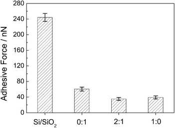 | ||
Fig. 6 Adhesive forces between AFM tip and the various surfaces. The molar ratio of HCTQ to TA is 0![[thin space (1/6-em)]](https://www.rsc.org/images/entities/char_2009.gif) : :![[thin space (1/6-em)]](https://www.rsc.org/images/entities/char_2009.gif) 1 (TA film), 2 1 (TA film), 2![[thin space (1/6-em)]](https://www.rsc.org/images/entities/char_2009.gif) : :![[thin space (1/6-em)]](https://www.rsc.org/images/entities/char_2009.gif) 1 (HCTQ+TA mixed film) and 1 1 (HCTQ+TA mixed film) and 1![[thin space (1/6-em)]](https://www.rsc.org/images/entities/char_2009.gif) : :![[thin space (1/6-em)]](https://www.rsc.org/images/entities/char_2009.gif) 0 (HCTQ film). 0 (HCTQ film). | ||
The nanotribological properties of the films were investigated by AFM. The friction force given here is in the form of voltage signal, which is proportional to the real friction force.23,32,41–43 Therefore, the friction forces of various film surfaces could be compared with each other directly when the same AFM tip was used. As shown in Fig. 7a, among the as-prepared films, single-component HCTQ film exhibits the highest friction force between the film and AFM tip. This is because there are vacant sites on silicon surface where no HCTQ molecule is adsorbed due to the semi-spherical molecular structure. Furthermore, the rigid structure of HCTQ molecule is difficult to swing along the sliding direction. TA film with liquidlike disordered structure, confirmed by FTIR spectrum, presents higher friction force than HCTQ+TA mixed film. Structural defects and collapsed sites existed in films always generate more energy loss, which leads to a high friction force. Our previous work of similar molecule has proved that the mixed film composed of crown-type molecule and straight chain molecule possessed higher packing density and only a few defects.30 For HCTQ+TA mixed film, a densely packed structure could be formed by the two-step assembly of crown-type molecule and alkylsilane. More densely packed and ordered monolayers inherently possess only a few conformational defects and present lower energy dissipation during the friction process, and thus exhibit lower friction.
The friction forces have approximately linear relationships with applied loads for different film surfaces. The linear relationship between friction force and load can be described by a modified form of Amonton's law, in which the lateral force (FL) is given by FL = μFN + F0, where FL is the lateral force, FN is the normal force, F0 is the friction force when the normal force is zero, and μ is the coefficient of friction.12,14,42,44
The term F0 is known to be controlled by the adhesion. According to the modified form of Amonton's Law, F0 could be obtained from the friction force versus load curves. Fig. 7b shows the relationship between F0 and adhesive force of the as-prepared films. When the normal force is zero, the hydroxylated silicon surface presents the highest friction, which is in agreement with the adhesive force. After introducing organic molecules on substrate, the film surfaces exhibit reduced adhesive force and friction force. Among the as-prepared films, HCTQ+TA mixed film possesses the lowest adhesive force, and the lowest friction force when the normal force is zero. HCTQ film exhibits higher friction force than TA film, although HCTQ film has lower adhesive force. It could be attributed to the semi-spherical molecular structure and the vacant sites on substrate surface.
In addition, the slope of the friction–load curve, proportional to the real friction coefficient, can be regarded as the relative friction coefficient.42,45 The relative friction coefficients of the films are directly derived from Fig. 7a, and the results are shown in Fig. 7c. For the prepared thin films, TA film has the highest relative friction coefficient owing to the higher surface energy of polarized amino groups. Reducing adhesion at nanoscale would decrease the friction and relative friction coefficient of thin films.37,43
3.3. Microtribological behavior of the thin films
Improving the anti-wear property of thin films is a scientific and practical issue in micromechanical systems, so it is necessary to evaluate the tribological properties of the films at microscale. The ball-on-plate microtribometer was employed to estimate the microtribological properties, and the results are shown in Fig. 8. TA film exhibits poor tribological properties with a friction coefficient of 0.17 and a wear life of 800 s under a load of 0.05 N and a sliding frequency of 0.5 Hz. For HCTQ film, the friction coefficient keeps at 0.15 and rises sharply after 11![[thin space (1/6-em)]](https://www.rsc.org/images/entities/char_2009.gif) 000 s, which means that the film has failed completely. HCTQ+TA mixed film shows the best anti-wear property with an extended wear life over 21
000 s, which means that the film has failed completely. HCTQ+TA mixed film shows the best anti-wear property with an extended wear life over 21![[thin space (1/6-em)]](https://www.rsc.org/images/entities/char_2009.gif) 000 s under the same test conditions. When the applied load is increased to 0.1 N, all of the wear lives of the as-prepared films decrease. It is observed that the friction coefficient of TA film keeps at a higher value of 0.18, and the friction coefficient rises sharply after 400 s. The friction coefficient of HCTQ film gradually rises from 0.15 and to 0.4 dramatically after about 3000 s. Under the same friction conditions, the mixed film exhibits better anti-wear performance with a friction coefficient of 0.15 and a wear life of 5500 s.
000 s under the same test conditions. When the applied load is increased to 0.1 N, all of the wear lives of the as-prepared films decrease. It is observed that the friction coefficient of TA film keeps at a higher value of 0.18, and the friction coefficient rises sharply after 400 s. The friction coefficient of HCTQ film gradually rises from 0.15 and to 0.4 dramatically after about 3000 s. Under the same friction conditions, the mixed film exhibits better anti-wear performance with a friction coefficient of 0.15 and a wear life of 5500 s.
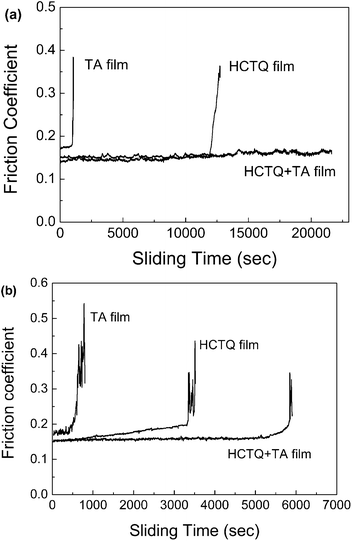 | ||
| Fig. 8 Variation in friction coefficient with sliding time for various films at sliding frequency of 0.5 Hz and different applied loads: (a) 0.05 N and (b) 0.1 N. | ||
Based on the experimental results above, we can conclude that the excellent tribological properties of HCTQ+TA mixed film might be attributed to the synergic effect of the load-carrying phase and friction-reducing phase, as schematized in Fig. 2. The crown-type molecule with rigid backbone promotes the load-carrying capacity for the mixed film, and the multiple functional groups in the crown-type molecule enhance the stability of the film against rubbing the counterpart ball. Meanwhile, alkylsilane with flexible backbone can swing along the sliding direction during reciprocating movement, which lowers shear strength and reduces the friction coefficient. Furthermore, as compared with neat TA film and HCTQ film, the mixed film composed of crown-type molecule and alkylsilane can form more densely packed and ordered film. This results in the improvement of the load-carrying capacity and the significant reduction of the energy dissipation during the friction process. Distinctively, the mixed film possesses much better load-carrying capacity and lower friction, and might be used as potential lubricant in MEMS/NEMS.
4. Conclusions
The mixed film composed of crown-type molecule and alkylsilane was formed on silicon substrate by a two-step self-assembly method, and their single-component films have been prepared as comparison. The relationship between the chemical structure and the tribological behavior of the thin films was studied. The results show that the mixed film containing rigid crown-type molecule and flexible alkylsilane exhibits much better tribological properties than the single-component films, which is attributed to the synergic effect between load-carrying phase and friction reducing phase. The multiple functional groups in the crown-type molecule enhance the stability and antiwear properties of the film, while the flexible alkylsilane serves as lubricant to reduce friction. In addition, the step by step assembly of crown-type molecule and straight chain molecule can form a densely packed mixed monolayer, which is beneficial to improving the durability of the mixed film.Acknowledgements
The authors gratefully acknowledge the National Natural Science Foundation of China (Grant no. 20673131), and Natural Science Foundation of Gansu Province, China (Grant no. 1112RJZA035) for financial support.Notes and references
- R. Maboudian and C. Carraro, Annu. Rev. Phys. Chem., 2004, 55, 35 CrossRef CAS PubMed.
- B. Bhushan, T. Kasai, G. Kulik, L. Barbieri and P. Hoffmann, Ultramicroscopy, 2005, 105, 176 CrossRef CAS PubMed.
- S. H. Kim, D. B. Asay and M. T. Dugger, Nano Today, 2007, 2, 22 CrossRef.
- N. S. Tambe and B. Bhushan, Nanotechnology, 2004, 15, 1561 CrossRef CAS.
- R. Maboudian, W. R. Ashurst and C. Carraro, Tribol. Lett., 2002, 12, 95 CrossRef.
- Z. Rymuza, Microsyst. Technol., 1999, 5, 173–180 CrossRef.
- H. Liu and B. Bhushan, Ultramicroscopy, 2003, 97, 321 CrossRef CAS.
- Z. Zheng, H. Zhao, W. Fa, W. He, K. Wong, R. W. M. Kwok and W. M. Lau, RSC Adv., 2013, 3, 11580 RSC.
- T. Zhang, Z. Cheng, Y. Wang, Z. Li, C. Wang, Y. Li and Y. Fang, Nano Lett., 2010, 10, 4738 CrossRef CAS PubMed.
- T. Liu, Y. Yu, S. Chen, Y. Li and H. Liu, RSC Adv., 2013, 3, 9973 RSC.
- B. Xin and J. Hao, RSC Adv., 2012, 2, 5141 RSC.
- Y. Wan, Y. Wang, Q. Zhang, Z. Wang, Z. Xu, C. Liu and J. Zhang, Appl. Surf. Sci., 2012, 259, 147 CrossRef CAS PubMed.
- N. J. Brewer, T. T. Foster, G. J. Leggett, M. R. Alexander and E. McAlpine, J. Phys. Chem. B, 2004, 108, 4723 CrossRef CAS.
- J. E. Houston, C. M. Doelling, T. K. Vanderlick, Y. Hu, G. Scoles, I. Wenzl and T. R. Lee, Langmuir, 2005, 21, 3926 CrossRef CAS PubMed.
- S. Song, S. Ren, J. Wang, S. Yang and J. Zhang, Langmuir, 2006, 22, 6010 CrossRef CAS PubMed.
- H. Liu and B. Bhushan, Ultramicroscopy, 2002, 91, 185 CrossRef CAS.
- J. Ou, J. Wang, S. Liu, J. Zhou and S. Yang, J. Phys. Chem. C, 2009, 113, 20429 CAS.
- J. Ou, Y. Wang, J. Wang, S. Liu, Z. Li and S. Yang, J. Phys. Chem. C, 2011, 115, 10080 CAS.
- J. Lahiri, L. Isaacs, B. Grzybowski, J. D. Carbeck and G. M. Whitesides, Langmuir, 1999, 15, 7186 CrossRef CAS.
- R. G. Chapman, E. Ostuni, L. Yan and G. M. Whitesides, Langmuir, 2000, 16, 6927 CrossRef CAS.
- Z. Burton and B. Bhushan, Nano Lett., 2005, 5, 1607 CrossRef CAS PubMed.
- S. Li, P. Cao, R. Colorado, Jr, X. Yan, I. Wenzl, O. E. Shmakova, M. Graupe, T. R. Lee and S. S. Perry, Langmuir, 2005, 21, 933 CrossRef CAS PubMed.
- Q. Zhang and L. A. Archer, J. Phys. Chem. B, 2003, 107, 13123 CrossRef CAS.
- A. Lio, D. H. Charych and M. Salmeron, J. Phys. Chem. B, 1997, 101, 3800 CrossRef CAS.
- X. Xiao, J. Hu, D. H. Charych and M. Salmeron, Langmuir, 1996, 12, 235 CrossRef CAS.
- J. M. Tour, L. Jones, D. L. Pearson, J. J. S. Lamba, T. P. Burgin, G. M. Whitesides, D. L. Allara, A. N. Parikh and S. Atre, J. Am. Chem. Soc., 1995, 117, 9529 CrossRef CAS.
- C. Fuxen, W. Azzam, R. Arnold, G. Witte, A. Terfort and C. Wöll, Langmuir, 2001, 17, 3689 CrossRef CAS.
- R. Arnold, A. Terfort and C. Wöll, Langmuir, 2001, 17, 4980 CrossRef CAS.
- I. Choi, Y. Kim, S. K. Kang, J. Lee and J. Yi, Langmuir, 2006, 22, 4885 CrossRef CAS PubMed.
- L. Chen, X. Cao and J. Zhang, Appl. Surf. Sci., 2010, 256, 1647 CrossRef CAS PubMed.
- L. Zhou, X. P. Cao, B. Neumann, H. G. Stammler and D. Kuck, Synlett, 2005, 18, 2771 Search PubMed.
- Q. Zhang and L. A. Archer, Langmuir, 2005, 21, 5405 CrossRef CAS PubMed.
- P. Harder, K. Bierbaum, Ch. Woell and M. Grunze, Langmuir, 1997, 13, 445 CrossRef CAS.
- Y. Li, Y. Liu, N. Wang, Y. Li, H. Liu, F. Lu, J. Zhuang and D. Zhu, Carbon, 2005, 43, 1968 CrossRef CAS PubMed.
- E. M. E. Kristensen, F. Nederberg, H. Rensmo, T. Bowden, J. Hilborn and H. Siegbahn, Langmuir, 2006, 22, 9651 CrossRef CAS PubMed.
- U. Srinivasan, M. R. Houston, R. T. Howe and R. Maboudian, J. Microelectromech. Syst., 1998, 7, 252 CrossRef CAS.
- S. L. Ren, S. R. Yang, J. Q. Wang, W. M. Liu and Y. P. Zhao, Chem. Mater., 2004, 16, 428 CrossRef CAS.
- S. L. Ren, S. R. Yang and Y. P. Zhao, Langmuir, 2004, 20, 3601 CrossRef CAS.
- S. L. Ren, S. R. Yang, Y. P. Zhao, J. F. Zhou, T. Xu and W. M. Liu, Tribol. Lett., 2002, 13, 233 CrossRef CAS.
- O. P. Khatri and S. K. Biswas, J. Phys. Chem. C, 2007, 111, 2696 CAS.
- E. E. Flater, W. R. Ashurst and R. W. Carpick, Langmuir, 2007, 23, 9242 CrossRef CAS PubMed.
- N. J. Brewer, B. D. Beake and G. J. Leggett, Langmuir, 2001, 17, 1970 CrossRef CAS.
- S. Song, J. Zhou, M. Qu, S. Yang and J. Zhang, Langmuir, 2008, 24, 105 CrossRef CAS PubMed.
- T. T. Foster, M. R. Alexander, G. J. Leggett and E. McAlpine, Langmuir, 2006, 22, 9254 CrossRef CAS PubMed.
- N. J. Brewer and G. J. Leggett, Langmuir, 2004, 20, 4109 CrossRef CAS.
| This journal is © The Royal Society of Chemistry 2014 |

