Endler M. Borges*a,
Mauricio A. Rostagnob and
M. Angela A. Meirelesb
aUniversidade do Oeste de Santa Catarina (UNOESC), Núcleo Biotecnológico. Rua Paese, 198, Bairro Universitário – Bloco K, Videira-SC, CEP 8956.0000, Brasil. E-mail: marcelborgesb@gmail.com; Fax: +55-49-35334444; Tel: +55-49-35334479
bLASEFI, Department of Food Engineering, School of Food Engineering, University of Campinas (UNICAMP), Rua Monteiro Lobato, 80, Campinas, SP 13083-862, Brazil
First published on 29th April 2014
The need for increased throughput and superior performance has increased the demand for stationary phases with improved kinetic performance. Among them, increasing the sample throughput of the ever-growing number of necessary (routine) analyses has become a popular target for reducing precious time. For the past thirty years, high-performance liquid chromatography (HPLC) has been the leading technology when it comes to various analyses; however, the requirement of typically 10–45 min for serial analyses has been a sample throughput-limiting barrier. Recently, the fundamentals of HPLC have been exploited to develop new technologies that can speed up analyses to ground-breaking limits without compromising separation efficiency. This paper reviews the most promising technologies, including porous sub-2 μm ultra-performance liquid chromatography (UPLC) and fused-core particle technology, which have the potential to take LC to the next level. As each analytical method has its own demands, the advances of the above mentioned technologies are discussed for different applications where high throughput analysis can be meaningful. Moreover, we discuss and compare the perspectives of these technologies.
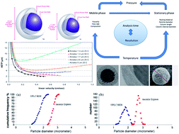
Several decades ago, the trend to employ smaller particles for faster and more efficient separation was foreseen. Not long ago, the goal was to achieve highly efficient packing with particles with diameters between 5 and 10 μm.1 Nowadays, this trend is continuing, and current liquid chromatography stationary phases have even smaller particles with diameters ranging between 1.3 and 3.5 μm. However, in addition to smaller and more uniform particles with several different chemistries, currently there is also a need for stationary phases with increased kinetic performance to allow faster and more efficient separation.2,3 Scientists are particularly interested in using rapid and efficient procedures for qualitative and quantitative analyses to cope with a large number of samples and to reduce the time required for the delivery of results. In this aspect, reducing analysis time and ensuring the quality of a separation in HPLC requires high kinetic efficiency.4
Higher efficiency and faster separation have always been of great interest in HPLC and have become increasingly important in recent years mainly because of the challenges posed by more complex samples or an increase in the number of samples.4 In fields such as metabolomics and proteomics, where samples are very complex, it is necessary to improve the separation efficiency of the stationary phase. This can be achieved by changing the chemistry of the stationary phase, increasing the column length of the stationary phase and reducing the particle diameter. To reduce the analysis time, increased kinetics performance is required. In this context, the ratio of the hold-up time to column efficiency can be used to assess the resolving power of a separation system, which is favoured with columns that possess high porosity and low plate heights while operating under high linear velocities, as summarized in Fig. 1.5
It is obvious that each application will require different conditions to achieve the proposed objective. Some applications can be achieved in a short time because the resolution requirements are low, while some applications require high resolution and are not achievable in a short time. This is largely dependent on the sample complexity, clearly suggesting a compromise between resolution and analysis time.6,7 For example, in order to analyse relatively simple samples, with only a few compounds, in short times, the column length can be decreased and the linear velocity of the mobile phase can also be increased to reduce the retention of compounds by the stationary phase. In this case, short columns (10–50 mm) may be sufficient to afford reasonable selectivity.
Combining high speed and high efficiency is the ideal scenario, but unfortunately, it is difficult to achieve these with complex samples. Therefore, it is necessary to sacrifice resolution for analysis time and vice versa.6,7 Thus, a balance between speed and high efficiency must be found. In this context, this review is dedicated to discussing the improved kinetic performance of totally porous sub-2 μm stationary phases and sub-3 μm partially porous (core–shell) stationary phases and their application for the analysis of macromolecules.
The effect of particle size (dp) in efficiency can be explained by the van Deemter equation (eqn (1)), which describes the relationship between efficiency (expressed as the height equivalent to a theoretical plate, H) and linear velocity (μ), in which λ is a packing constant, γ is an obstruction factor for diffusion in a packed bed, Dm is the diffusion coefficient of analyte in the mobile phase and f(k) is a function of the retention factor (k).
![]() | (1) |
The C-term, which is considered to mainly represent the resistance to mass transfer in the mobile phase, is directly proportional to the square of the particle size. Thus, a decrease in particle diameter results in a large decrease in the plate height, especially at high linear velocities.8
The position of the minimum on the HETP curve and the optimum linear velocity can be determined by the use of differential calculus. The optimum linear velocity occurs when the slope of the H versus μ curve is zero, i.e. when dH/dμ = 0. This condition is satisfied in eqn (2).8
![]() | (2) |
Fig. 2 illustrates the van Deemter equation (eqn (1)) for several stationary phases with particle sizes ranging between 5 and 1.3 μm. It shows that stationary phases with reduced particle sizes afford increased efficiencies. Furthermore, reduced particle sizes result in an increased μopt, as described in eqn (2).
![]() | ||
Fig. 2 Experimental H–μ plots of columns packed with 1.3, 1.7, 2.6 and 5 μm core–shell particles (peak widths were corrected for the extra-column band broadening). The test solution was eluted with water/acetonitrile 63/37 on the Kinetex 1.3 μm column. The mobile phase consisted of water/ACN 62/38 (v/v) for the 1.7 μm and 2.6 μm Kinetex columns, and a mixture of water/ACN 60/40 (v/v) for the 5 μm column, to maintain the same retention factors for the test solutes on the different columns. The column efficiency of butylparaben was considered. The mobile phase ensured a retention between k = 6–7. (Reproduced with permission from ref. 14). |
On the other hand, the reduction in particle size not only improves peak capacity but also greatly increases the pressure generated by the column. For example, the pressure drop of the column, ΔP, is proportional to 1/dp2 with the linear velocity (μ), according to the Kozeny–Carman equation.9 (Eqn (3), where ϕ is the flow resistance factor, η is the viscosity of the solvent, L is the length of the packed bed and dp represents the particle diameter.10–13) Considering that reduced particle size results in an increased μopt, ΔP is proportional to 1/dp3 at the optimal linear velocity (μopt). For example, in Fig. 2, it was not possible to reach μopt using the stationary phases with 1.3 μm because of the high back pressure generated by those very fine particles.
![]() | (3) |
Unfortunately, the increase in pressure caused by smaller particles reaches the pressure limits of conventional HPLC systems (400 bar) with particles of approximately 3 μm. Smaller particles increase the pressure drop and allow only a low mobile phase velocity, which in turn provide low column efficiency (Fig. 2).14
In order to take advantage of packing materials with particles smaller than 2 μm (sub-2 μm particles) special systems are required. These systems, termed ultrahigh-pressure liquid chromatography (UHPLC) systems, have low dwell volumes and are capable of withstanding the higher pressure caused by the sub-2 μm particles while maintaining a relatively high linear velocity to provide high column efficiency. UHPLC has been defined as a type of liquid chromatography utilizing sub-2 μm particles.15 Indeed, the main advantages of this technique are the high separation power (theoretical plate counts from 100000 to 300
000) and reduced run times. As previously mentioned, the main disadvantage of this technique is the high back pressure generated.16–26
The first commercial UHPLC system (Acquity, Waters Corp.) and columns packed with porous 1.7 μm hybrid silica particles (Acquity BEH stationary phases) were introduced in 2004, and were able to withstand pressures up to 1000 bar.23,27,28 Currently, more than 100 different columns packed with 1.5–2 μm particles from about 15 providers as well as about 20 different UHPLC systems with pressure limits between 600 and 1300 bar are available in the market.28–30 For example, in Fig. 2, the optimal linear velocity and thus the lowest possible H value could not be reached before exceeding the upper pressure limit of the Waters Acquity UPLC™ I-Class instrument (1070 bar reached at μ = 0.5 cm s−1 at T = 25 °C). It implies that with such a column, the major contribution to band broadening is longitudinal diffusion (B-term dominated region).
Unfortunately, separation efficiency is not only influenced by the particle diameter and the mobile phase velocity, but also by several other parameters and characteristics of the system. Because of the higher efficiency achievable with smaller particles at high μ, column dimensions can be reduced to shorten analysis time and save solvent. In addition to shorter columns with reduced internal diameters, column void volume is also reduced in UHPLC columns to minimize diffusion of sample components and band broadening. Another characteristic of UHPLC systems when compared with conventional HPLC systems is the reduced extra-column volume.
Although there were great improvements in instrumentation in the last decades, the loss in apparent column efficiency can still be very significant, even in modern UHPLC equipment,28–30 and further improvements in instrument design (smaller dispersion) are required to take full advantage of columns packed with sub-2 μm particles.30 According to Fekete and Fekete,30 it is not possible to fully utilize the potential of these small columns with current instrumentation. The loss in efficiency was estimated to reach 30–55% with commercially optimized UHPLC systems. This suggests that the performance of the stationary phases is limited by the equipment itself and not by the characteristics of the stationary phase.
Nowadays, several types of equipment can reach back pressures between 600 and 1200 bar. However, fast chromatography has low retention volume and needs equipment with low dead volume. For example, at 50–60 °C, HPLC equipment could work with a 50–100 mm long column packed with particles between 2.5–1.7 μm sizes. In this case, the conventional HPLC equipment could generate a back pressure sufficient for running analyses using these columns, but band broadening from the equipment could destroy the separation.
Fig. 3 shows several UHPLC equipments from different suppliers. The figure also shows the maximum back pressure that these equipments can tolerate and their dwell volume.31
![]() | ||
Fig. 3 Graphical representation of A, pressure tolerance and type of pumping system; and B, standard system dwell volume of all the commercially available UHPLC systems (ΔP > 600 bar). In A, light red denotes low pressure system volume, while dark blue represents high pressure system volume. It is important to note that the standard dwell volume reported in this figure can be modified on a few instruments either by passing the damper and mixer or by changing the volume of the mixing chamber. (Figure reproduced from ref. 31). |
In fact, the lower the retention volume, the greater the effect of extra column band broadening on efficiency loss. Thus, increased retention volume could reduce the efficiency loss due to extra column band broadening. For example, in Fig. 4, theoretically, these columns should provide the same column efficiency. However, the column efficiency for the propiophenone peak decreases as column diameters are decreased.32 The equipment used in this example is a Waters Acquity UPLC system (Milford, MA, USA) and is one of the UHPLC equipments with lower dead volume shown in Fig. 3. Thus, columns with 3–4.6 mm diameters should be preferred instead of columns with 2.1 mm diameters.
![]() | ||
Fig. 4 Effect of column diameters on efficiency. Chromatograms for columns with four different internal diameters. Conditions: Zorbax SB Extend C-18, 1.8 μm particles; 50 mm column length; flow rates for 4.6, 3.0, 2.1 and 1.0 mm I.D. columns were 1.4, 0.60, 0.29 and 0.067 mL min−1, respectively; the injection volumes 4.6, 3.0, 2.1 and 1.0 mm I.D. columns were 4.8 μL, 2.0 μL, 1.0 μL and 0.23 μL, respectively; the sample concentration was 0.1 mg mL−1 for each analyte; peak identifications from left to right: (1) uracil; (2) benzylalcohol; (3) acetophenone; (4) propiophenone and (5) benzophenone. (Figure reproduced from ref. 32). |
When columns packed with particles of small diameter are used in a conventional LC instrument, the use of columns with diameters close to 4.6 mm could alleviate the efficiency loss due to band broadening. For example, in our researching group, several analyses are run with conventional HPLC equipment, using 50–100 mm long and 4.6 mm diameter columns packed with particles of sizes between 2.5–1.7 μm.
Another consideration in the upper pressure limit of the current systems (1.100–1.300 bar) is related to the frictional heating phenomenon, which is induced by the movement of the mobile phase through the column bed at very high pressure. The generated heat dissipates along and across the chromatographic column, allowing the formation of axial (longitudinal) and radial temperature gradients.28–30 These thermal gradients may influence both the retention and column efficiencies. The efficiency loss due to these thermal gradients could be dramatic and perhaps limit increased performance by straightforward particle-size reduction.33 On the other hand, thermal conductivity is higher in core–shell columns due to the solid cores of the particles. The radial thermal gradients are lower in columns of totally porous particles of the same particle size pumped with the same mobile phase at the same velocity. Improved heat dissipation allows further reduction of the core–shell particle size before encountering mobile-phase heating problems.33
In addition, some alteration in the retention due to the high back pressure achieved with this technique is expected because the pressure alone can have a significant effect on retention. However, the effects are much more pronounced with large and ionized analytes. An increase in the average column pressure of 500 bar can increase the retention of ionized bases and acids by as much as 50% under typical operating conditions.34–37 Large proteins, which have several ionizable functionalities and may undergo conformational changes under ultra-high pressure conditions, have shown a pronounced increase in retention as the pressure is increased. For example, the retention of myoglobin (MW ∼ 17 kDa) increased more than 3.000% with an increase in pressure from 100 to 1.100 bar.36
In contrast, the use of elevated temperatures reduces the pressure of the system by affecting the viscosity of the mobile phase and reduces the retention of analytes by increasing mass transfer rates.38 Because the mobile phase viscosity can be dramatically reduced by an increase in temperature, resulting in lower back pressures, separations carried out at high temperatures may take greater advantage of sub-2 μm particles.39
Extra-column variance leading to peak broadening and frictional heating are considered important factors, limiting the performance of the separations with stationary phases with sub-2 μm particles. Another limiting factor is the difficulty in packing uniform beds with even-smaller particles using current techniques. Because of these drawbacks, the performance achieved in practice with sub-2 μm particles (totally porous or core–shell) is smaller than the performance that can be theoretically achieved.40–43
To illustrate this aspect, we can consider a recent study by Fekete et al.,44 in which several stationary phases with particle diameters ranging between 1.5 and 3.0 μm were evaluated for the separation of pharmaceutical products, as shown in Fig. 5. This comparison was conducted using the Knox equation,7 which uses reduced plate heights (h = H/dp) and linear velocities (ν = μdp/D). They observed that a similar efficiency can be achieved with columns packed with 1.9–2.1 μm particles and with smaller particles (1.5–1.8 μm). When the particle size was 2.5 μm or larger, the theoretically expected values and experimental data of plate heights were in good agreement, indicating that the full performance potential of the stationary phases was being utilized. It was suggested that the use of reduced particle size results in lower efficiencies than should be expected due to the high dead volume of equipment, frictional heating effects and the difficulty in packing uniform beds with smaller particles using current technologies.44
![]() | ||
Fig. 5 Knox curves of commercially available sub-3 μm and sub-2 μm packed columns obtained with ethinyl estradiol. Experiments were conducted on 5 cm long narrow bore columns in 48/52 ACN/H2O at 35 °C, DM = 1.15 × 10⁻⁵ cm2. (Reproduced with permission from ref. 44). |
![]() | ||
Fig. 6 Cartoon graphic and SEM microphotograph of fused-core particle with 400 Å pores. (Reproduced with permission from ref. 45). |
These partially porous particles (core–shell particles) consist of a solid inner core surrounded by a porous outer layer. In comparison with totally porous particles with similar diameters, the diffusion path is much shorter because the inner core is solid-fused silica, which is not accessible to the analytes interacting with the particle. The shorter diffusion path influences the resistance to mass transfer (the C term in the van Deemter equation), which tends to limit the axial dispersion of solutes and minimize peak broadening, especially at elevated linear velocities. In addition, this material has an exceptionally narrow particle-size distribution and high packing density compared with porous particles (Fig. 7), leading to a smaller A term in the van Deemter equation (i.e. eddy diffusion).46
![]() | ||
Fig. 7 Cumulative frequency (a) and particle-size distribution (b) of Ascentis Express 2.7 μm shell particles and Waters UPLC BEH 1.7 μm porous particles. (Reproduced with permission from ref. 46). |
Cabooter et al.47 have studied the particle-size distribution (Fig. 8) and van Deemter curves of several sub-3 μm core–shell and 3–3.5 totally porous particles. They observed that core–shell particles have narrower distribution than totally porous particles, as shown in Fig. 8. The core–shell particles also afforded higher efficiency than the totally porous particles. The van Deemter plots have shown that core–shell stationary phases have lower A and B terms than totally porous particles, but not lower C terms. In fact, for small molecules, such as the pharmaceuticals studied by Cabooter et al.,47 core–shell stationary phases do not have lower C terms than totally porous stationary phases, which is due to the roughness of core–shell stationary phases (see Fig. 6).
![]() | ||
Fig. 8 Normalized particle-size distributions of the different evaluated support types, determined from SEM pictures. XBridge C18 (dp = 3.5 μm) (![]() ![]() ![]() ![]() ![]() ![]() ![]() |
Core–shell particles have a much lower A-term contribution at high velocities, compared with fully porous columns.46 This implies that a superficially porous column can be operated at three to four times its optimum velocity and still have the same or better performance than that of the fully porous column; this is illustrated in Fig. 9,48 where t example chromatograms are shown measured on the 250 mm 4.6 mm columns, packed with the fully and superficially porous 5 μm particles. Fig. 9A and C show the separation of three alkylphenones at an optimum flow rate of 1 mL min−1 for the Kinetex and Zorbax columns, respectively. Chromatograms measured on the 5 μm core–shell and fully porous particle columns are compared at different flow rates. At the optimal flow rate μopt, the number of theoretical plates of the core–shell particle columns is ca. 30% higher than the fully porous particle columns, which is directly related to the difference in (reduced) plate height. When going to a higher flow rate (e.g. almost three times μopt), this difference increases to more than 75% (see eqn (2)). This does not happen because core–shell stationary phases have lower C-terms than the totally porous stationary phases, but it happens because core–shell stationary phases have lower A and B terms than totally porous stationary phases.48
![]() | ||
Fig. 9 Chromatograms and performance recorded on the Kinetex 250 mm × 4.6 mm 5 μm core–shell particle column (A and B) and the Zorbax 250 mm × 4.6 mm 5 μm fully porous particle column (C and D) at their optimal flow rates (A–C) and a flow rate almost three times higher than the optimal flow rate (B–D). Test solutes were uracil, butyrophenone, benzophenone and valerophenone. (Reproduced with permission from ref. 48). |
Because of its low A and B terms, sub-3 μm core–shell stationary phases can reach peak capacities comparable to sub-2 μ totally porous particles.49 For example, Fig. 10 shows that sub-3 μ core–shell stationary phases afford a peak capacity closely related to one of the most popular sub-2 μm totally porous stationary phases.49
![]() | ||
Fig. 10 Representative chromatogram of test samples. Conditions: the volume fractions of acetonitrile at the beginning and at the end of the gradient were set at 40% and 90%, the columns (5 cm × 2.1 mm) were thermo-stated at 30 °C and the injected volume was 0.5 μL. The gradient time was set at 3 min at a flow-rate of 0.8 mL min−1. Analytes: degradation products/impurities of ethinyl-estradiol (1, 2, 4, 5 and 13), dienogest (3), ethinyl-estradiol (6), estradiol (7), finasteride (8), bicalutamide (9), gestodene (10), levonorgestrel (11), tibolone (12), and noretistherone-acetate (14). Peak 1, 6, 7, 8, 9, 10, 11, 12, 13 and 14 were considered for peak-capacity calculations. (Reproduced with permission from ref. 49). |
When this review was written, core–shell stationary phases were available just as type B silica materials, while ZirChrom PDB, which is a polybutadiene-coated zirconia stationary phase, was the only sub-2 μm non-silica stationary phase available in the market.50 The type C silica51–56 is a very promising material, and it is possible to prepare sub-2 μm totally porous and core–shell stationary phases based on type C silica. However, core–shells and sub-2 μm stationary phases based on Type C silica were not available, which may be attributed to the fact that type C silica has a small market.
The core–shell technology is still evolving and the number of commercially available stationary is rapidly increasing. Several new brands of core–shell stationary phases are introduced. Table 1 summarizes some of the new brands, which are commercially available.
Supplier | Product name | Particle diameter (μm) | Shell thickness (μm) | Surface chemistries |
---|---|---|---|---|
Macherey-Nagel (Düren, Germany) | Nucleoshell (90 Å) | 2.7 | 0.5 | RP-18, phenyl-hexyl, pentafluorophenyl and HILIC (ammonium – sulfonic acid) |
ChromaNik Technologies Inc. (Osaka, Japan) | SunShell (90 Å) | 2.6 | 0.5 | C18, C8, phenyl, PFP, 2-ethylpyridine (2-EP), and HILIC-amide |
ChromaNik Technologies Inc. (Osaka, Japan) | SunShell (160 Å) | 2.6 | 0.5 | WP-C18 and RP-AQUA |
ChromaNik Technologies Inc. (Osaka, Japan) | SunShell HFC18–16 (160 Å) and SunShell HFC18–30 (300 Å) | 2.6 | 0.5 | HFC18 stationary phase is an Hexa-Functional C18. It has six functional groups, and it is prepared using a mixture of hexamethyldichlorotrisiloxane + trimethylchlorosilane |
Agilent (Palo Alto, CA, USA) | Poroshell 300 (300 Å) | 5 | 0.25 | SB-C18, C8, C3, extended |
Agilent (Palo Alto, CA, USA) | Poroshell 120 (120 Å) | 2.7 | 0.50 | EC-C18, EC-C8, EC-CN, SB-C18, SB-C18, SB-Aq, Bonus-RP, Phenyl-Hexil, HILIC (SB stationary phases are non-end-capped, EC stationary phases are end-capped) |
Advanced Material Technology (Wilmington, Delaware, USA) | Halo (90 Å) | 2.7, 5.0 | 0.5, 0.60 | C18, C8, HILIC, RP-amide, phenylhexyl, pentafluorophenyl |
Advanced Material Technology (Wilmington, Delaware, USA) | Halo Peptide-ES (160 Å) | 2.7 | 0.50 | C18 |
Phenomenex (Torrance, California, USA) | Kinetex (100 Å) | 5, 2.6, 1.7, 1.3 | 0.35, 0.23 | C18, XB-C18, C8, HILIC and pentafluorophenyl |
Sigma-Aldrich (Bellefonte, Pennsylvania, USA) | Ascentis Express (90 Å) | 2.7, 5.0 | 0.50 | C18, C8, HILIC, RP-amide, phenylhexyl, pentafluorophenyl |
Sigma-Aldrich (Bellefonte, Pennsylvania, USA) | Ascentis Express Peptide-ES 160 Å | 2.7 | 0.50 | C18 |
Sigma-Aldrich (Bellefonte, Pennsylvania, USA) | BIOshell A160 peptide (160 Å) | 2.7, 5 | CN, C18, CN, C18 | |
Sigma-Aldrich (Bellefonte, Pennsylvania, USA) | BIOshell A400 protein (400 Å) | 3.4 | C4 | |
Thermo Scientific (Faltam detalhes) | Accucore (80 Å) | 2.6 | 0.50 | C18, aQ, RP-MS, HILIC, phenylhexyl, pentafluorophenylpropyl (PFP), polar premium |
Thermo Scientific | Accucore XL (80 Å) | 4 | C8, C18 and Amide-HILIC | |
Thermo Scientific | Accucore nanoViper 150 (150 Å) | 2.6 | 0.5 | C4 and C18. |
Thermo Scientific | Accucore (80 Å) | 2.6 | 0.5 | C18, RP-MS, C8, AQUA, polar premium, phenyl-hexyl, PFP, phenyl-X, C30, HILIC and urea-HILIC |
Phenomenex (Torrance, California, USA) | Aeris Widepore (200 A), Aeris peptide (100 Å), Aeris peptide (100 Å) | 3.6, 1.7, 3.6 | 0.2, 0.22, 0.5 | XB-C18, XB-C8, C4 |
Wissenschaftliche Geratebau (Berlin, Germany) | BlueShell (80 Å) | 2.6 | C18, C18 AQUA, HILIC | |
PerkinElmer (Waltham, Massachusetts, USA) | Brownlee (90 Å) | 2.7 | 0.5 | C18, C8, HILIC (bare silica), pentafluorophenylpropyl (PFP), phenylhexyl and RP-amide |
PerkinElmer (Waltham, Massachusetts, USA) | Brownlee peptide ES-C18† (160 Å) | 2.7 | 0.5 | C18 |
Shiseido (Japan) | CAPCELL CORE (90 Å) | 2.7 | 0.5 | Polymer coating |
Protea Biosciences Group, Inc. (Morgantown, West Virginia, USA) | Amplus (300 and 160 Å) | 2.6 | C8, C18 and C4 | |
Waters (Milford, Massachusetts, USA) | CORTECS (90 Å) | 1.6 | 0.5 | C18, C18+ (CSH technology) HILIC |
Advanced Chromatography Technologies Limited. (Aberdeen, Scotland) | ACE UltraCore (95) | 2.5, 5 | C18, phenyl-hexyl | |
Restek (Bellefonte, Pennsylvania, USA) | Raptor (90 Å) | 2.7 | ARC-18 and Biphenyl | |
Nacalai (San Diego, California, USA) | Cosmocore (90 Å) | 2.6 | 1.6 | C18 |
The sub-3 μm core–shell and sub-2 μm totally porous stationary phases afford narrow peak shapes. However, only half- or one-third pressure is required to operate with a column packed with sub-3 μm core–shell material, compared with a column packed with 2 μm totally porous stationary phase, in agreement with Darcy's law and the Karman–Kozeny equation. The relatively high specific permeability of columns packed with sub-3 μm core–shell particles ranges between K0 = 4.6 × 10⁻¹¹ cm2 and 6.4 × 10⁻¹¹ cm2, while the permeability of a column packed with 1.7 μm totally porous stationary phase is ∼2.5 × 10⁻¹¹ cm2.57–59
A recent study evaluated the peak capacity of degradation products or the impurities of ethinyl-estradiol using a 3 min gradient time at a 0.8 mL min−1 flow rate with a sub-2 μm totally porous stationary phase (Acquity BEH C18) and an 18 min gradient time at 0.4 mL min−1 flow rate using sub-3 μm core–shell stationary phases (Kinetex C18, Ascentis Express C18, Poroshell C18) with columns of 50 × 2.1 mm. Sub-3 μm core shell stationary phases generated half of the back pressure in comparison with a sub-2 μm stationary phase while being able to maintain approximately the same peak capacity.49 In another study, the efficiencies of core–shell stationary phases (Ascentis Express and Kinetex) and sub-2 μm totally porous stationary phases (Acquity BEH, Grace Vision HT and Hypersil Gold) were evaluated using estradiol and ivermectin as test probes.41 Sub-3 μm core–shell and sub-2 μm totally porous materials provided very similar efficiencies for both test compounds. However, one of the columns (Kinetex C18) showed a smaller C term than the others (the Ascentis Express C18 and the sub-2 μm stationary phases). In addition, the degradation products/impurities of ethinyl-estradiol were separated within the same duration in the sub-3 μm core–shell and sub-2 μm totally porous materials.
The enhanced performance of core–shell stationary phases is related to its higher permeability when compared with totally porous stationary phases, which is derived from the narrow particle-size distribution. The sub-3 μm core–shell stationary phases have lower eddy diffusion and higher mass transfer resistance for small analytes than the sub-2 μm totally porous stationary phases. In this aspect, Fekete et al.46 compared a core–shell-type stationary phase (Ascentis Express C18; 50 × 2.1 mm, 2.7 μm) with several sub-2 μm totally porous stationary phases [Acquity BEH C18 (50 × 2.1 mm, 1.7 μm), Grace Vision HT C18 column (50 × 2.0 mm, 1.5 μm) and Hypersil Gold C18 (50 × 2.1 mm, 1.9 μm)] using hormones as test probes. They observed that the plate heights generated by the 2.7 μm core–shell material were comparable to those produced by sub-2 μm particles. Surprisingly, the C term in the van Deemter formula for Ascentis Express C18 was higher than those observed with the sub-2 μm totally porous stationary phases, which implies that the comparable efficiency of ∼3 μm core–shell with sub-2 μm totally porous stationary phases are due to reduced eddy diffusion. Higher C terms shown by the core–shell stationary phases were attributed to their rough surface. Although, it can be expected to observe lower efficiencies of the core–shell column due to the higher value of the C term because there is a reduced A term, and comparable efficiencies are observed for both core–shell and sub-2 μm columns.
Fekete et al.46 observed that a sub-3 μm core–shell stationary phase [Ascentis Express C18 (2.7 μm)] affords efficiencies comparable to sub-2 μm totally porous stationary phases [Grace Vision C18 (1.5 μm), Acquity BEH C18 (1.7 μm) and Hypersil Gold C18 1.9 μm] for the separation of a mixture of steroids. It was also observed that the core–shell stationary phase afforded a back pressure lower than the sub-2 μm stationary phase due to its higher permeability. In addition, the core–shell stationary phases are able to separate a mixture of steroids in less than 2 min.46
In some cases, the pressures achieved with sub-3 μm stationary phases are in the range of 400 bar, which is compatible with the conventional LC equipment.38,60,61 However, core–shell stationary phases or sub-2 μm totally porous stationary phases produce peaks with low retention volumes, which implies that the chromatographic performance might be severely compromised by the extra volume from the equipment. The same discussion was illustrated in Fig. 4. When using sub-3 μm partially porous and sub-2 μm totally porous stationary phases, one of the primary considerations influencing the separation is the LC equipment. Even the most current UHPLC systems have limitations regarding how well they can reflect the true performance of a core–shell and sub-2 μm stationary phases.8,28
The dead volume of the system influences the chromatographic performance of the separation, and this factor increases its importance as the dimensions of the column becomes smaller. However, judicious selection of the column dimensions can alleviate the situation. Short columns are demanding since they generate peaks with very small volumes, and the effect of extra column volume will be less pronounced as the volume (both length and I.D.) of the column is increased.62
With the realization that column performance is limited by the instrument characteristics and the wide presence of conventional HPLC in laboratories, researchers began to modify the configuration of their systems to improve the performance. Several modifications in the conventional HPLC instrumentation are required to optimize the system volume and achieve the full potential of core–shell stationary phases. It has also been suggested that separation conditions should be adjusted when using core–shell stationary phases to improve separations.63 Conventional systems are not optimized for achieving fast and efficient separations when using small narrow-bore columns packed with sub-3 μm core–shell stationary phases. However, the use of columns with 4.6 mm I.D. may provide improved separations without a significant loss in column efficiency.28,64–66
Bobály et al.67 compared the chromatographic performance of Waters Cortecs 1.6 μm, Phenomenex Kinetex 1.3 μm and Phenomenex Kinetex 1.7 μm, which are sub-2μ core–shell stationary phases. In terms of kinetic performance, the Kinetex 1.3 μm particles provide exceptional performance (Hmin of 1.95 μm) but suffer from very low permeability. Thus, this column cannot be employed under optimal linear velocity conditions, even on the best UHPLC systems (ΔPmax of 1200 bar). Alternatively, the Kinetex 1.7 μm packing offers a two-fold higher permeability but the kinetic performance is lower (Hmin of 3.17 μm). The best compromise appears to be the Cortecs 1.6 μm phase that possesses both a reasonable permeability (similar to that of Kinetex 1.7 μm) and excellent kinetic performance (Hmin of 2.66 μm). This column outperforms the other two in the practically useful plate number and peak capacity ranges in terms of achievable analysis time. On the other hand, it was superior to the others for ultra-fast analysis (e.g. tgrad < 0.5 min). Meanwhile, to attain the full benefits of Kinetex 1.3 μm, a system possessing σec2 ≤ 1 μL2 is recommended.
Bobály et al.67 reinforce our opinion that sufficient equipments are not available currently that can work with sub-1.6 μm.
Basic pharmaceutical analysis can also be successful using core–shell stationary phases; however, one must take into account the detrimental interactions of basic compounds with these stationary phases in low ionic strength mobile phases with organic and amino buffers. For example, Ruta et al.68 used a sub-2 μm totally porous stationary phase [Acquity BEH C18, (50 × 2.1 mm, dp 1.7 μm)], which was compared with several sub-3 μm core–shell stationary phases [Poroshell 120 EC-C18 (50 × 2.1 mm, 2.7 μm), Kinetex C18, (50 × 2.1 mm, 2.6 μm) and Halo C18 (50 × 2.1 mm, 2.7 μm)] for the analyses of 13 acidic and basic pharmaceuticals. The separation of these 13 pharmaceuticals was achieved in less than 3 min with all the tested stationary phases. The separations were obtained under LC-MS compatible conditions (B = 0.1% formic; A = 0.1% formic acid in acetonitrile; gradient profile: 5% A for 1 min, then 5–95% A in 3 min) and with phosphate buffer (A = phosphate buffer (20 mM, pH: 6.85); B = ACN; gradient profile: 5% ACN for 1 min, then 5–95% ACN in 3 min). In addition, a similar loadability of the stationary phases was observed for all the stationary phases under LC-MS compatible conditions.
Another study compared the performances of totally porous (Acquity BEH-C18) and partially porous (Kinetex-C18) stationary phases with the same dimensions and particle sizes (50 × 2.1 mm, 1.7 μm) for the separation of small pharmaceuticals and larger charged molecules (peptides) under LC/MS-compatible conditions (i.e. 0.1% formic acid, pH 2.8; 0.05% trifluoroacetic acid, pH 2.4; 10 mM ammonium acetate, pH 6.8; 0.1% ammonium hydroxide, pH 10.6; 10 mM ammonium formate, pH 2.8 and 10 mM ammonium formate, pH 10.4).68
The partially porous column provided higher efficiency than the totally porous stationary phase for neutral solutes (ethylparaben and caffeine). However, both stationary phases provided lower efficiency for diphenhydramine than those obtained for caffeine. In both the cases, the obtained low efficiency values were attributed to the poor peak shapes. In this specific case, the partially porous column (Kinetex-C18) was less efficient for small basic pharmaceuticals due to detrimental interactions with the free silanols on the surface of this material. In contrast, the totally porous stationary phase (Acquity BEH-C18) is based on hybrid silica and has lower amounts of free silanols than the partially porous column (Kinetex-C18).68
The combination of the lower pressure caused by the lower viscosity of the solvents used in the mobile phase and partially porous columns can be explored to provide high resolution and short analysis times. For example, several basic (nortriptyline, diphenhydramine, benzylamine, procainamide), neutral (caffeine and phenol) and acidic (2-naphthalenesulfonic acid and p-xylenesulfonic acid) pharmaceuticals were separated using a 45 cm long column packed with core–shell particles [three Halo silica columns (15 cm × 4.6 mm, 2.7 μm) coupled in series], with efficiencies of higher than 100000 plates per meter. Even though three columns were coupled in series, a relatively low system pressure was reported (250 bar) using acetonitrile–ammonium formate (85
:
15 v/v) as a mobile phase at a flow rate of 1 mL min−1.70
However, an important aspect of superficially porous columns for HILIC separation is that column efficiency is not influenced at high flow rates, which implies that shorter analysis times could be achieved at higher flow rates while generating acceptable pressure levels.
The use of sub-3 μm core–shell and sub-2 μm totally porous stationary phases in the HILIC mode is a valuable tool for achieving fast and efficient separations of basic pharmaceuticals and to reduce frictional heating with sub-2 μm totally porous stationary phases. For example, Okusa et al.71 had shown that dextromethorphan is a highly challenging test probe, even for modern RP stationary phases. In this context, separation of midazolam, bupropion, dextromethorphan and their main metabolites (OH-midazolam, OH-bupropion, and dextrorphan) in the HILIC mode (mobile phase: 10 mM formate buffer (pH 3; 10 mM) and ACN: 30 °C; flow rate: 0.5 mL min−1; gradient profile: 95% ACN for 1.20 min, then 95–80% MeCN in 3 min; slope: 5% min−1) using Acquity BEH HILIC (100 × 2.1 mm, 1.7 μm) and Ascentis HILIC (100 × 2.1 mm, 2.7 μm) columns was recently reported. The separation was achieved with symmetric peaks on both columns in 4.5 min. The observed back pressures were also reasonable (375 and 150 bar, for Acquity BEH HILIC and Ascentis HILIC, respectively). In this case, the high amount of organic modifier used was responsible for the low back pressure generated and for the good peak shape observed.72
High-pressure drop and frictional heating obtained with sub-2 μm totally porous stationary phases are not relevant in HILIC, whereas the long equilibration times are observed with totally porous 5 μm stationary phases in the HILIC mode are reduced with sub-2 μm totally porous stationary phases. These observations were made by Periat et al.,73 who provided a complete guide for the method developed using sub-2 μm totally porous stationary phases.
In this aspect, both partially porous and sub-2 μm totally porous stationary phases can provide several advantages. In fact, the core–shell materials were developed to limit the diffusion of macromolecules into the pores of the stationary phase to improve their separation.74
A comparison of modern partially porous (Kinetex C18) and sub-2 μm totally porous (Acquity BEH C18) stationary phases (with same dimensions and particle sizes) for the separation of proteins of different sizes revealed that for small molecules, both stationary phases had similar efficiencies. In contrast, for large molecules, the partially porous stationary phase showed higher efficiency than that for the totally porous.75
However, it is important to highlight that even partially porous stationary phases could result in poor resolution of macromolecules if their pore sizes are not large enough. For example, Gritti and Guiochon76 observed that a partially porous stationary phase (Halo C18) with 90 Å pore diameter provided lower efficiencies and higher C terms than totally porous stationary phases [Atlantis (dp 3 μm and 101 Å pore diameter)] because the pore size was not large enough for the large proteins utilized as test probes in this study.
In large-molecule analyses, core–shell stationary phases may afford higher efficiencies than totally porous particles, when the pore sizes are large enough to allow penetration by macromolecules. This aspect is illustrated in a recent study, in which a large pore core–shell stationary phase (Aeris WP C18 – 3.6 μm particle diameter) was compared with large-pore totally porous stationary phases (Acquity BEH300 C18 and C4; both with 3.6 μm particle diameter and 300 Å pore sizes) to analyze macromolecules (recombinant monoclonal antibodies). It was reported that the partially porous stationary phases provided higher efficiencies than totally porous stationary phases due to the limited diffusion of macromolecules into the pores of the partially porous column.77
Another interesting example was reported by Ricker and co-workers.78 They compared a wide pore (300 Å) 5 μm totally porous stationary phase (Zorbax 300SB-C18 and Zorbax 300Extend-C18) with (300 Å) 5 μm partially porous stationary phases (Poroshell 300SB-C18, 300SB-C8, 300SB-C3, and 300Extend-C18) for the separation of peptides and proteins with molecular weights ranging from 1673 to 950000 Daltons. They observed that peptides and proteins show less peak broadening at high flow rates (linear velocity) on wide-pore, superficially porous particles compared with those of totally porous particles.
Gritti et al.79 compared columns packed with the partially porous particles (2.7 μm) and those with totally porous particles (3 μm), both stationary phases with 90 Å pore size for the separation of naphthalene, insulin (5.8 kDa), lysozyme (14.3 kDa), and β-lactoglobulin (18.4 kDa) were used as test solutes. They observed that shell structures do not seem to bring any advantage, compared with a totally porous structure for low molecular weight compounds with respect to mass transfer kinetics. However, it leads to faster kinetics for high molecular weight compounds and allows markedly improved performance at high flow rates. For compounds with low diffusivities such as proteins or large peptides, the mass transfer kinetics are faster and the C term of the partially porous column is about half of a column packed with totally porous silica particles.
In this context, it was suggested in a recent review article that the development of new stationary phases with wide-pore core–shell particles or fully porous sub-2 μm 300 Å particles allow the fast and efficient separation of peptides and proteins in the RPLC mode.77 The analysis of recombinant monoclonal antibodies (mAbs) is an interesting example of how the developments of wide-pore sub-2 μm totally porous and wide-pore totally porous particles have opened new horizons in macromolecular analysis. mAbs are glycoproteins that belong to the immunoglobulin (Ig) family. They have become particularly relevant for the treatment of autoimmune diseases or cancers.80 In 2010, the global therapeutic mAbs market was $48 billion.80 Their analysis was mainly achieved by electrophoretic approaches,80 but the introduction of wide-pore sub 2 μm totally porous and wide-pore totally porous particles boosted the development of highly efficient analytical methods for mAbs in the RPLC mode.80,81 These methods62,63 were developed with the totally porous stationary phases (Acquity BEH-300 C18 and C4, 1.7 μm particles with a pore size 300 Å) and partially porous columns (Aeris Widepore C18 and C4, 3.6 μm particles and 300 Å pores).
There are several examples of applications of partially porous technology for the analysis of macromolecules. In one study, the separation of monoclonal IgG2 disulfide isomers was achieved in 10 min using a partially porous stationary phase (Poroshell300SB-C8 – 150 × 2.1 mm, 5 μm, 300 Å).82 A similar column was used [Poroshell 300SB-C18 (75 mm × 2.1 mm, 5 μm)] for a fast (7 min) and direct determination of polysorbate 80 from an injection solution containing a four-helix bundle protein, which belongs to the family of cytokines.83 Another study also used a partially porous stationary phase (Halo Peptide-ES 160 Å; particle sizes ranging from 2.2 to 5 μm) for the analysis of several large molecules.84
Zirconia and titania have large pore sizes (∼300 Å). However, proteins are irreversibly retained on this material.85 This adsorption is the result of the high hydrophobicity of the polybutadiene coating and the strong Lewis acid sites on the zirconia surfaces causing strong interactions between the proteins and the stationary phases. This combination leads to the irreversible adsorption of proteins on polybutadiene-coated zirconia. However, while zirconia and titania are not useful as stationary phases in LC analysis of proteins, these materials are well-suited for solid-phase extraction of phosphorylated peptides.86 In addition, Rhinophase®-AB (ZirChrom, Anoka, USA) [prepared by refluxing particles of zirconia in a ethylenediamine-N,N′-tetra(methylenephosphonic) acid (EDTPA) solution] can effectively purify a wide range of Mab subclasses as well as polyclonal hIgG, IgA and IgM, as reported by Clausen et al.87
Nowadays, in my working group, we just use sub-3 μm core–shell stationary phases in conventional LC equipment (Waters Alliance e2695), and the columns are purchased in a 4.6 mm × 150 mm size to overcome band broadening. With these columns, we are able to achieve highly efficient separations in short durations. My working group had shared this experience with many separation groups at our University, and all other groups have adopted core–shell stationary phases.
This journal is © The Royal Society of Chemistry 2014 |