A novel aluminium–air secondary battery with long-term stability

Ryohei Mori *
Fuji Pigment Co.Ltd, 2-23-2 Obana, Kawanishi-city, Hyogo Prefecture 666-0015, Japan. E-mail: moriryohei@fuji-pigment.co.jp; Fax: +81-72-7599008; Tel: +81-72-7598501

Received 25th August 2013 , Accepted 15th November 2013

First published on 15th November 2013


Abstract

An aluminium–air secondary battery was fabricated by using an aluminium ion conductor, Al2(WO4)3, and plain salt water as an electrolyte. The battery functioned for approximately one month. It was also possible to enhance the cell capacity and suppress the yield of by-products, by modifying the cell structure.

There is an urgent need for clean fuel alternatives for energy supply and storage created by fossil fuel depletion and air pollution arising from combustion.1,2 To this end, metal–air batteries have garnered attention as potential high-performance power sources for electronic devices,3,4 of which lithium–air cells are the most promising for high-performance applications.5,6 However, lithium is sensitive to ambient conditions such as humidity and oxygen, and is a scarce natural resource in some regions.

Aluminium, in contrast, is an abundant, attractive anode material for energy storage and conversion because of its high specific capacity, highly negative standard electrode potential [E° = −1.7 V vs. standard hydrogen electrode (SHE)], and environmentally benign characteristics. In addition, aluminium is the most recycled metal in the world and is relatively inexpensive. When compared with zinc, lithium, and other metals, aluminium has unique advantages and disadvantages. Its relatively low atomic weight of 26.98 and trivalence confer it a gram-equivalent weight of 8.99 and an electrochemical equivalence of 2.98 A h−1 g−1, compared with 3.86 A h−1 g−1 for lithium, 2.20 A h−1 g−1 for magnesium, and 0.82 A h−1 g−1 for zinc. Moreover, on a per-volume basis, aluminium yields 8.04 A h−1 cm−3, compared with 2.06 A h−1 cm−3 for lithium, 3.83 A h−1 cm−3 for magnesium, and 5.85 A h−1 cm−3 for zinc.7

A major barrier to commercialization is aluminium's high self-corrosion rate in alkaline solutions, both under open-circuit conditions and during discharge. To reduce the self-corrosion of the aluminium anode, two methods are usually employed: alloying aluminium with other elements8–10 or modifying the composition of the electrolyte.11–16 However, these research has been largely unsuccessful for the commercial production of Al–air cells because by-products such as Al2O3 and Al(OH)3 accumulate at both the anode and cathode. Therefore, we propose to cover the aluminium anode and the air cathode with ceramic aluminium ion conductors, preventing anode corrosion resulting from direct contact with the electrolyte, while retaining aluminium ion conduction. In addition, this method may prevent by-product accumulation and suppress electrolyte evaporation (the major drawback of all metal–air batteries).

In a previous study of ours, Al2(WO4)3 was used as an aluminium ion conductor on both the anode and air cathode, and we succeeded in preparing an Al–air cell with secondary battery properties that was stable for one week.17 However, by-products such as Al2O3 and Al(OH)3 still formed on the aluminium ion conductor at both the anode and the cathode.

In this study, by using a plain salt water as an electrolyte, we have fabricated an Al–air cell which functioned for approximately 1 month with the absence of Al2O3 and Al(OH)3. Furthermore, the cell capacity was largely enhanced by combining conductive carbon and ceramic aluminium ion conductor as the air cathode material.

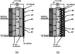
In our previous study, the Al–air cell was termed AFLA as an acronym of its major components: an aluminium anode, an Al2(WO4)3 film, an Al2(WO4)3 lid, and an air cathode17 (Fig. 1). (We refer to the material which covers the air cathode as the “lid”.) An aluminium board was used as the anode. The air cathode was composed of conductive carbon and polyvinylidenedifluoride (PVDF) dissolved in N-methyl-pyrrolidone on a nickel mesh current collector. The Al2(WO4)3 film was prepared by coating the aluminium anode with a printing slurry composed of Al2(WO4)3 powder and terpineol, followed by annealing at 500 °C. A 10% NaCl aqueous solution was used as the electrolyte. The pH of the electrolyte was adjusted to 6.7–6.8.


image file: c3ra44659j-f1.tif
Fig. 1 A schematic figure of AFLA cell: (a) AFLA-A cell and (b) AFLA-AC cell.

In this study we prepared Al–air cells with two different lid compositions. The first lid was made of Al2(WO4)3 (AFLA-A cell); the second lid was a mixture of Al2(WO4)3 and conductive carbon (AFLA-AC cell). The powders were mixed in respective ratios of 9[thin space (1/6-em)]:[thin space (1/6-em)]0[thin space (1/6-em)]:[thin space (1/6-em)]1 and 8[thin space (1/6-em)]:[thin space (1/6-em)]1[thin space (1/6-em)]:[thin space (1/6-em)]1 (Al2(WO4)3[thin space (1/6-em)]:[thin space (1/6-em)]carbon[thin space (1/6-em)]:[thin space (1/6-em)]PVDF), and pressed into disks. The structure of the prepared cells can be summarized as Al | Al2(WO4)3|NaCl | Al2(WO4)3| air cathode (AFLA-A, Fig. 1(a)) and Al | Al2(WO4)3|NaCl | Al2(WO4)3 + carbon | air cathode (AFLA-AC, Fig. 1(b)).

Fig. 2 show fifteen discharge curves of the prepared Al–air cells at an applied current of 0.2 μA (cm−2) for the AFLA-A cell and 0.1 mA (cm−2) for the AFLA-AC cell. The cut-off potential was 0.2 V. for AFLC-A cell, the capacity was initially 8.96 μA h cm−2, but dropped to 8.85 μA h cm−2 and 8.29 μA h cm−2 at the 5th and 15th cycles, respectively. Capacity is smaller than previous study when NaOH was used as an electrolyte (Fig. 3).17


image file: c3ra44659j-f2.tif
Fig. 2 Discharge curve of Al–air cells: (a) AFLA-A cell and (b) AFLA-AC cell.

image file: c3ra44659j-f3.tif
Fig. 3 Discharge curve of Al–air cell from previous article ref. 17.

Generally, cell capacity is larger when NaOH was used as an electrolyte.7 However. at the AFLA-AC cell, even with NaCl electrolyte, the initial capacity was 3.12 mA h cm−2, but dropped to 3.04 mA h cm−2 and 2.95 mA h cm−2 at the 5th and 15th cycles, respectively. This large capacity difference is responsible for the applied current differing between the AFLA-A and AFLA-AC cells. It is obvious that the cell capacity is much larger in the AFLA-AC cell.

However, we had observed that capacity and voltage faded with cycle number. We suggest this fading is due to deterioration of the AFLA cell itself. The AFLA cell is under development as a secondary battery and not yet robust enough. We especially suggest that the “lid” needs to be strengthened in order to maintain high capacity and voltage even after long-term use.

At the air cathode, the water in the electrolyte reacts with oxygen from the air:

O2 + 2H2O + 4e → 4OH

This reaction is accelerated by the close proximity of the electrolyte to the conductive carbon, which is an active air cathode material. In other words, existence of conductive carbon as electron conductor in the lid, electron migration was accelerated in the AFLA-AC cell. We propose that this is the main reason for the enhanced capacity. However, as the reviewer points out that this is only a suggestion. In order to investigate this issue, we will need to conduct more-detailed future research. For example, we could see the effect of varying carbon content in the lid. Furthermore, we could attempt to use other types of air cathode materials such as active carbon, Mn2O3 and LaFeO3 to investigate variation in conductivity and performance even further.18–20 In addition, both the AFLA-A and ALFA-AC cells exhibited stable discharge capacity for fifteen cycles, suggesting that they were quite stable when NaCl was used as the electrolyte.

Fig. 4(a)–(d) display charge–discharge curves collected over twenty-eight days at an applied current of 0.2 μA (cm−2) for the AFLA-A cell and 0.1 mA (cm−2) for the AFLA-AC cell. Each figure displays the charge–discharge curves of the first and last four days of the measurement period. To the best of our knowledge, this is the longest measurement period reported for charge–discharge curves of an Al–air cell.21,22 Previous studies regarding Li–Air battery performance similarly provided data of charge–discharge voltage against time to evaluate secondary battery functionality.23–25 However, it should be noted here that due to evaporation of the electrolyte, the NaCl solution was refilled once every five days to ensure sufficient electrical contact. We suggest that the electrolyte evaporation was attributable to macro- and micro-pores formed in the lid because of the simplicity of the lid preparation technique. This issue needs to be further investigated and improved for future study.26


image file: c3ra44659j-f4.tif
Fig. 4 Charge–discharge curve of AFLA cell. (a) 1st four days of AFLA-A cell. (b) Last four days of AFLA-A cell. (c) 1st four days of AFLA-AC cell. (d) Last four days of AFLA-AC cell.

Fig. 5 shows the voltage profiles of the AFLA-AC cell as a function of the time. The cell was discharged galvanostatically under different rates from 0.05 mA cm−2 to 0.5 mA cm−2. The cut-off voltage was 0.1 V in all cases. At discharge rates between 0.05 and 0.2 mA cm−2, the voltage profiles were kept almost constant. With increasing discharge rates, the progressive decline of discharge voltage was observed. When discharge current was 0.05 mA cm−2, the capacity was 1.572 mA h cm−2. As discharge current increases as 0.1,and 0.2 mA h cm−2, the capacity were 2.904 and 5.472 mA h cm−2, respectively. But for 0.5 mA cm−2, the discharge curve of cell became a slope instead of plateau, and discharge capacity decreased to 4.68 mA h cm−2.


image file: c3ra44659j-f5.tif
Fig. 5 Discharge curves of AFLA-AC cell at different discharge rates.

Fig. 6 is the cyclic voltammograms of the AFLA-AC cell for the first, 3rd, 5th, 10th and 20th cycles measured between 0 and 2.0 V to characterize the redox reactions. Anodic current increases largely at the 3rd cycle compared to 1st cycle, although anodic current lowers as cycle number increases and become similar to the 1st current (at 20 th cycle). The reduction and oxidation peak positions for every cycle's are relatively the same at 1.2–1.3 V and 1.4–1.5 V respectively. This demonstrates that the redox pairs contribute to the gain and loss of electrons in AFLA-AC cell during cell charge–discharge reaction. The reason for high intensities at 3–10 th cycle is unknown, however this fact indicates the higher electrochemical reactivity at 3–10 th cycle.


image file: c3ra44659j-f6.tif
Fig. 6 Cyclic votammograms of AFLA-AC cell.

Fig. 7 shows X-ray diffraction patterns of the Al2(WO4)3 powder, lid, and film, before and after each experiment. Fig. 7(a) shows the X-ray diffraction pattern of the commercially available Al2(WO4)3 powder used in this study, which was composed of Al2(WO4)3 and WO3 phases. After one month of charge–discharge experiments, the lid composed of Al2(WO4)3 still exhibited both Al2(WO4)3 and WO3 phases (Fig. 7(b)). On the other hand, the lid composed of Al2(WO4)3 and carbon had a NaCl phase after the same period (Fig. 7(c)). Fig. 7(d) shows the X-ray analysis result of the Al2(WO4)3 film of the AFLA-A. The Al2(WO4)3 film had dissolved and an Al metal phase originating from the substrate was detected. Fig. 7(e) displays the magnified image of Fig. 7(d) between 10 and 40 degrees in 2θ. NaAl23O35(β-alumina), Na11WO3, AlO (aluminium oxide (II)) and Al(OH)3 phases were observed, and Al2(WO4)3 was still detectable. When the lid was composed of Al2(WO4)3 and carbon, the Al anode substrate also was exposed due to Al2(WO4)3 dissolution and AlO(OH) (aluminium hydroxide oxide) was observed on the substrate film (Fig. 7(f) and (g)). However, typical by-products such as AlOH3 and Al2O3 that inhibit the secondary battery reaction were not observed. One might infer that this is why we were able to run charge–discharge measurements for one month with a higher cell capacity than for the AFLA-A cell.


image file: c3ra44659j-f7.tif
Fig. 7 X-ray diffraction pattern of materials prepared in this study: (a) Al2(WO4)3 powder purchased for this study, (b) the lid after charge–discharge reaction for one month with NaCl electrolyte for AFLA-A Cell. (c) The lid after charge-discharge reaction for one month with NaCl electrolyte for AFLA-AC Cell. (d) The film after charge-discharge reaction for one month with NaCl electrolyte for AFLA-A Cell. (e) Magnified image of Fig. 4(d) between 10 and 40 degrees in 2θ. (f) The film after charge-discharge reaction for one month with NaCl electrolyte for AFLA-AC Cell. (g) Magnified image of Fig. 4(f) between 10 and 40 degrees in 2θ.

We attempt to explain the yield of the different crystalline phases on the anode as compared to when a NaOH electrolyte was used in our previous study, by analyzing the reactions taking place using a NaCl electrolyte.27

OH is produced at the cathode as in the following reaction:

O2 + 2H2O + 4e → 4OH

Then, OH migrates through the electrolyte to reach the Al anode, where the following discharge reaction occurs:22

Al + 4OH → Al(OH)4 + 3e

However, OH must first transit the Al2(WO4)3 thin film before reaching the Al metal anode. We reason that the porosity of the Al ion conductor due to our nano-size particle dispersion preparation method is responsible for allowing OH to travel through pores in the Al ion conductor film and reach the Al anode in order to continue the reaction.

Hence, the overall Al–air cell reaction is:

4Al + 3O2 + 6H2O + 4OH → 4Al(OH)4

Eventually, aluminium hydroxide precipitates:

Al(OH)4 →Al(OH)3 + OH

In our previous study, when NaOH was used as the electrolyte, AlOH3 and Al2O3 were observed in the film and the lid. When NaOH was used as an electrolyte, Al(OH)3 is the charge-carrying ion species.28 On the other hand, when NaCl is used as an electrolyte, Al(OH)3 and transitory compounds such as Al(OH)2Cl, Al(OH)Cl2, and AlCl3 are the charge carriers.29 These different charge-carrying species may be the reason for the yields of different crystalline phases at the anode. Thus far, the typical by-products of the aluminium ion battery that inhibit the cell reaction have been reported to be Al(OH)3 and Al2O3.30 In this study, various types of other chemicals were detected, including NaAl23O35, Na11WO3, AlO and AlO(OH). For example, β-alumina is known to be a good sodium ion conductor and has been used as a solid electrolyte in NaS batteries.31 However, the influence of these chemicals needs to be clarified since their effects on aluminium air batteries have not yet been studied.7 On the other hand, a different crystalline phase precipitated on the lid after the measurement. In fact, when the lid was soaked in aqueous NaCl without applying an electrical bias, the X-ray diffraction showed evidence of phases of Al2(WO3)4 in the AFLA-A cell and NaCl in the AFLA-AC cell, respectively (data not shown). One can infer that NaCl tends to precipitate on carbon more readily than on Al2(WO3)4.

Conclusions

We successfully assembled a functional Al–air cell with an AFLA structure using plain salt water as an electrolyte. Moreover, by combining the air cathode active material and the solid electrolyte, we were able to achieve a higher cell capacity. Future work will be required to fabricate a cell in which the aluminium ion conductor film does not dissolve at the anode, by using either another electrolyte or another aluminium ion conductor with better Al3+ conductivity.32,33 Importantly, we have shown that aluminium is a reasonable option for a secondary cell material, as it is more abundant, safer, and easier to handle than other candidate metals such as lithium, zinc, magnesium, and sodium.

Acknowledgements

The author wishes to express thanks to Dr Sadayoshi. Mori and Mr.Kazuo Sakai for helpful discussions.

Notes and references

  1. R. Padbury and X. Zhang, J. Power Sources, 2011, 196, 4436–4444 CrossRef CAS PubMed .
  2. J. Chen, J. S. Hummelshøj, K. S. Thygesen, J. S. G. Myrdal, J. K. Nørskov and T. Vegge, Catal. Today, 2011, 165, 2–9 CrossRef CAS PubMed .
  3. P. Kichambare, J. Kumar, S. Rodrigues and B. Kumar, J. Power Sources, 2011, 196, 3310–3316 CrossRef CAS PubMed .
  4. M. Armand and J. Tarascon, Nature, 2008, 451, 652–657 CrossRef CAS PubMed .
  5. G. Girishkumar, B. McCloskey, A. Luntz, S. Swanson and W. Wilcke, J. Phys. Chem. Lett., 2010, 1, 2193–2203 CrossRef CAS .
  6. F. Wagner, B. Lakshmanan and M. Mathias, J. Phys. Chem. Lett., 2010, 1, 2204–2219 CrossRef CAS .
  7. Q. Li and N. Bjerrum, J. Power Sources, 2002, 110, 1–10 CrossRef CAS .
  8. S. Abedin and A. Saleh, J. Appl. Electrochem., 2004, 34, 331–335 CrossRef .
  9. M. Krishnan and N. Subramanyan, Corros. Sci., 1977, 17, 893–900 CrossRef CAS .
  10. M. Paramasivam and S. Iyer, J. Appl. Electrochem., 2001, 31, 115–119 CrossRef CAS .
  11. D. Macdonald and C. English, J. Appl. Electrochem., 1990, 20, 405–417 CrossRef CAS .
  12. H. Shao, J. Wang, Z. Zhang, J. Zhang and C. Cao, Mater. Chem. Phys., 2002, 77, 305–309 CrossRef .
  13. Y. Ein-Eli, M. Auinat and D. Starrosvetsky, J. Power Sources, 2003, 114, 330–337 CrossRef CAS .
  14. A. Maayta and N. Al-Rawashdeh, Corros. Sci., 2004, 46, 1129–1140 CrossRef CAS PubMed .
  15. A. Mukherjee and I. Basumallick, J. Power Sources, 1996, 58, 183–187 CrossRef CAS .
  16. S. Licht, R. Tel-Vered, G. Levitin and C. Yarnitzky, J. Electrochem. Soc., 2000, 2, 496–501 CrossRef PubMed .
  17. R. Mori, RSC Adv., 2013, 3, 11547–11551 RSC .
  18. H. Dong, H. Yu and X. Wang, Environ. Sci. Technol., 2012, 46, 13009–13015 CrossRef CAS PubMed .
  19. M. Augustin, O. Yezerska, H. Borchert, T. Plaggenborg and D. Fenske, ECS Trans., 2013, 45, 1–10 CrossRef PubMed .
  20. T. Takeguchi, et al. , J. Am. Chem. Soc., 2013, 135, 11125–11130 CrossRef CAS PubMed .
  21. J. B. Wang, J. M. Wang, H. B. Shao, X. T. Chang, L. Wang, J. Q. Zhang and C. N. Cao, Mater. Corros., 2009, 60, 269–273 CrossRef CAS .
  22. M. Nestoridi, D. Pletcher, R. J. K. Wood, S. Wang, R. L. Jones, K. R. Stokes and I. Wilcock, J. Power Sources, 2008, 178, 445–455 CrossRef CAS PubMed .
  23. E. Yoo and H. Zhou, J. Power Sources, 2013, 244, 429–434 CrossRef CAS PubMed .
  24. Y. Wang, P. He and H. Zhou, Adv. Energy Mater., 2012, 2, 770–779 CrossRef CAS .
  25. E. Yoo and H. Zhou, ACS Nano, 2011, 5, 3020–3026 CrossRef CAS PubMed .
  26. R. Mori, T. Ueta, K. Sakai, Y. Niida, Y. Koshiba, L. Lei, K. Yamaguchi, K. Nakamae and Y. Ueda, J. Mater. Sci., 2011, 46, 1341–1350 CrossRef CAS .
  27. A. A. Mohamad, Corros. Sci., 2008, 50, 3475–3479 CrossRef CAS PubMed .
  28. S. I. Pyun and S. Y. Moon, J. Solid State Electrochem., 2000, 4, 267–272 CrossRef CAS .
  29. K. Y. Chan and R. F. Savinell, J. Electrochem. Soc., 1991, 138, 1976–1984 CrossRef CAS PubMed .
  30. A. M. Abdel-Gaber, E. Khamis, H. Abo-ELDahab and S. Adeel, Mater. Chem. Phys., 2008, 109, 297–305 CrossRef CAS PubMed .
  31. Z. Wen, J. Cao, Z. Gu, X. Xu, F. Zhang and Z. Lin, Solid State Ionics, 2008, 179, 1697–1701 CrossRef CAS PubMed .
  32. N. Imanaka and S. Tamura, Bull. Chem. Soc. Jpn., 2011, 84, 353–362 CrossRef CAS .
  33. N. Imanaka, Y. Hasegawa, M. Yamaguchi, M. Itaya, S. Tamura and G. Adachi, Chem. Mater., 2002, 14, 4481–4483 CrossRef CAS .

This journal is © The Royal Society of Chemistry 2014