Effect of size and content of mesoscopic fillers on the polymerization induced viscoelastic phase separation
Jie
Zhang
,
Tian
Li
,
Zhongnan
Hu
,
Huiping
Wang
and
Yingfeng
Yu
*
State Key Laboratory of Molecular Engineering of Polymers, Department of Macromolecular Science, Fudan University, Shanghai, 200433, China. E-mail: yfyu@fudan.edu.cn; Fax: +86 21 6564 0293; Tel: +86 21 6564 2865
First published on 7th November 2013
Abstract
Fillers have great impact on the phase separation process and material properties of multi-component heterogeneous polymer composites. In this article, we have investigated the effect of surface affinity, size and content of mesoscopic fillers on the polymerization induced viscoelastic phase separation of thermoplastic modified thermosets by using optical microscopy, time-resolved light scattering, and dynamic mechanical analyses. Nanosized mesoscopic silica type fillers, both surface treated and untreated, showed significant enhancement effect on the viscoelastic phase separation of polyethersulfone modified epoxy resins with dynamic asymmetry, which resulted in a clear decrease of characteristic length scale of phase structure and an increase of relaxation time of phase separation. With increase of filler size from nanoscale to micron-size, the “enhanced viscoelastic effect” of fillers at the same content diminished quickly as both the phase evolution process and the size of phase structure shifted to those of blends without fillers. While increase of the content of fillers showed an enlarged enhancement effect on viscoelastic phase separation. Glass transition temperatures of filled blends with various filler contents and sizes obtained from dynamic mechanical study were consistent with the phase separation study.
1. Introduction
High performance polymeric materials are generally composed of multi-component polymers and various fillers to provide balanced properties for structural, electrical, and biological applications.1–3 The phase separation mechanism and structural evolution play important roles in the final morphology and properties of heterogeneous polymer composites,4 as a result, numerous studies have been performed in this research area, as well as in the field of thermosetting materials.5–9The conventional phase separation theories of binary blends are based either on a solid model or on a fluid model,10 while the phase-separation kinetics have been classified into two types: bicontinuous (and droplet) spinodal decomposition (SD) in the unstable region and nucleation–growth-type (NG) phase separation in the metastable region. The early stage of phase separation is well described by Cahn's linear theory11 and the Lifshitz–Slyozov–Wagner theory,10,12,13 respectively; while the late stage of phase separation follows self-similar growth and scaling laws.14 In both cases, no matter in the diffusion controlled solid model or in the diffusion and hydrodynamic transport fluid model, interfacial tension plays a major role during phase separation.
One the basis of those theoretical models, the effect of fillers on phase separation is usually found to have close relationship with their surface affinity. Micron-sized fillers were initially studied and showed preferential immersion to the phase with better surface affinity and pinned the phase structure due to low mobility of the filler particles.15
Furthermore, the effect of nanoscaled fillers on the phase separation behavior of binary polymer blends or block copolymers has also been widely studied both by experimental observation16–20 and by theoretical simulation21–24 in recent years. In binary blends containing spherical nano-fillers that interact more attractively with one of the two components, the fillers can only slightly affect the phase separation behavior.25 Even so, with well controlled processing conditions like dispersing nano-fillers into surface unfavorable polymer at first, nano-fillers may also act as compatibilizing agent of immiscible polymer blends,26–28 where nano-fillers are adsorbed at the interfaces between the immiscible fluids and generate long-lived metastable phase structure.29,30
However, all the above studies and theories are based on the concept of dynamic universality, which has fundamental differences to polymer blends with unique effect of viscoelasticity.31 From complex fluids like polymer solutions and colloidal suspensions, Tanaka et al.31–36 found another type of quite unusual phase separation, named “viscoelastic phase separation”, under deep-quench conditions with intrinsic ‘dynamic asymmetry’ from large differences either in size or in glass transition temperature between their components. The polymer chain entanglement of the slow part (slow dynamic) hinders the molecular-escaping of fast part from the slow-rich-phase. Thus the viscoelastic relaxation of the slow part dominates the phase structure evolution.37
In our previous works, we have observed a significant enhancement effect of mesoscopic fillers (meso-fillers) in viscoelastic phase separation of dynamic asymmetric polymer blends,38 no matter near or off-critical composition via SD or NG mechanisms.39 Due to the entanglement with polymer chains, meso-fillers of different shapes are preferentially immersed into the slow dynamic phase, which further increases the dynamic asymmetry and enforces elastic-force balance condition in phase separation, and thus induces distinct differences of phase structure compared with blends without fillers.
However, our previous work focused mainly on the effect of nano-sized fillers of different shape on the viscoelastic phase separation. As the entanglement of slow-dynamic phase with filler surface may be closely related to the filler size and content, one would wonder: which is the key point that decides the extent of “enhanced viscoelastic effect” of meso-fillers; what is the effect of surface affinity of fillers on the phase separation; and what is the difference between fillers of various sizes and contents?
As numerous works have demonstrated the selective distribution of fillers in the phase with better surface affinity during phase separation with dynamic symmetry, we hereby choose a thermoplastic-thermoset system with large dynamic asymmetry, which has been found to follow polymerization induced viscoelastic phase separation (PIVPS) as a common phenomenon for thermoplastic modified thermosetting resins,40–50 to study the surface effect on the viscoelastic phase separation. In this article, we demonstrate that the surface area of meso-fillers is the most important factor for the “enhanced viscoelastic effect” in the polymerization induced viscoelastic phase separation (PIVPS). Lowering down the surface area of meso-fillers through either enlarging filler size or decreasing filler content would diminish the “enhanced viscoelastic effect” due to lower interaction point between slow-dynamic phase and filler surface.
2. Experimental section
2.1 Materials
The epoxy oligomer used, DER331, was provided by Dow Chemical Co. and is a low molecular weight liquid diglycidyl ether of bisphenol A (DGEBA) with an epoxide equivalent of 182–192. The hardener is methyl tetrahydrophthalic anhydride (MTHPA) which is provided by Ciba-Geigy Co. N,N-dimethylbenzylamine (BDMA) from Aldrich was used as accelerator to modulate curing rate. All above were used as receive without further purification.Polyethersulfone (PES) was supplied by Jilin University, China, which has a weight-average molecular weight of 4.5 × 10⁴ and polydispersity of 2.4. The molecular weight of PES was measured with a PerkinElmer S-250 gel permeation chromatograph; polystyrene standards (Showa Denko, Ltd.) were employed to make the calibration curve.
Treated fumed silica (Cab-O-Sil TS-720, 115 m2 g−1) and untreated fumed silica (Cab-O-Sil M-5, 200 m2 g−1) provided by Cabot Corp have an average primary particle sizes of 14 nm, and 12 nm, respectively. Spherical silica with diameter of 100 nm and 2 μm bought from Aladdin Industrial Inc. (Shanghai, China) has a BET surface area of 55 m2 g−1, and 2 m2 g−1, respectively.
2.2 Specimen preparation
The compositions of the formulations studied are collected in Table 1. The formulations studied contain 13 wt% of PES, which is near the critical composition, and different type of filler, and filler content. The weight ratio of PES, DER331, MTHPA, and BDMA is 13, 46, 41, and 0.40.| Sample | Silica size | Surface | Weight percent of silica (%) |
|---|---|---|---|
| PES-13% | — | — | 0 |
| Un-12 nm-0.5% | 0.5 | ||
| Un-12 nm-1% | 12 nm | untreated | 1 |
| Un-12 nm-2% | 2 | ||
| Un-12 nm-5% | 5 | ||
| Tr-14 nm-0.5% | 0.5 | ||
| Tr-14 nm-1% | 14 nm | treated | 1 |
| Tr-14 nm-2% | 2 | ||
| Tr-14 nm-5% | 5 | ||
| Un-100 nm-0.5% | 0.5 | ||
| Un-100 nm-1% | 1 | ||
| Un-100 nm-2% | 100 nm | untreated | 2 |
| Un-100 nm-5% | 5 | ||
| Un-2 μm-0.5% | 0.5 | ||
| Un-2 μm-1% | 2 μm | untreated | 1 |
| Un-2 μm-2% | 2 | ||
| Un-2 μm-5% | 5 | ||
Fillers were added to the epoxy oligomer under nitrogen atmosphere with vigorous stirring and ultrasonicating at 100 °C for 6 hours and a homogeneous epoxy suspension was obtained. Thermoplastics were added to MTHPA with stirring in a sealed glass at 90 °C until a homogenous solution was formed. Epoxy suspension or neat epoxy (without filler), thermoplastic/MTHPA solution and BDMA were blended together with stirring at 90 °C until the mixture was homogeneous. The samples were degassed under vacuum for another few minutes and then cooled to −10 °C to prevent further curing.
2.3 Experimental techniques
A PerkinElmer Pyris 1 DSC instrument was used for the study of the curing reaction. The isothermal curing conversion was calculated from residual exotherms observed in scans in the temperature range of 50–350 °C, with heating rates of 10 °C min−1 and normalized by the total exotherms for uncured samples.The phase-separation process during the isothermal curing reaction was observed at real time and in situ on the self-made time-resolved light scattering (TRLS) instrument with controllable hot chamber.40,41 The change of the light scattering profiles was recorded at appropriate time intervals during isothermal curing. The blend of epoxy monomer with thermoplastics for TRLS observation was prepared by melt-pressing the film.
Optical light microscopy (OM) experiments were performed with an Olympus BX51P microscope equipped with an Instec HCS410 hot stage.
The morphologies of the isothermally cured blends were observed under a scanning electron microscope (SEM, Tescan TS 5163 MM) for samples fractured in liquid nitrogen. All samples were coated with gold and mounted on copper mounts.
The dynamic mechanical properties were collected with a Netzsch DMA 242 operating in the three-point-bending mode at multi oscillation frequencies of 1, 2, 5, and 10 Hz. The specimens for DMA were prepared in the form of cuboid bars with nominal dimension of 1 × 15 × 50 mm3 and the data were collected from ambient temperature to 260 °C at a scanning rate of 3 °C min−1.
3. Results and discussions
3.1 Effect of surface affinity of meso-fillers on the phase separation
The phase separation of blend without fillers was first studied to compare the difference with filled systems. Fig. 1 shows a typical evolution process of the PIVPS in the PES–epoxy system (sample PES-13%) studied by OM and TRLS, and similar behaviors have also been observed in numerous literatures40–47 In Fig. 1a, a micro-bicontinuous phase structure was observed by OM at the beginning of the phase separation; with polymerization the epoxy-anhydride precursors diffused out from the PES-rich phase (dark region) and coarsened rapidly. Then the morphology shifted into a phase inverted structure quickly with small epoxy-rich dispersed particles (bright region) with anisotropic shapes. With the elastic elongation and braking of the PES-rich regions, irregular epoxy-rich macro-phase domains dispersed in the PES-rich matrix were then formed.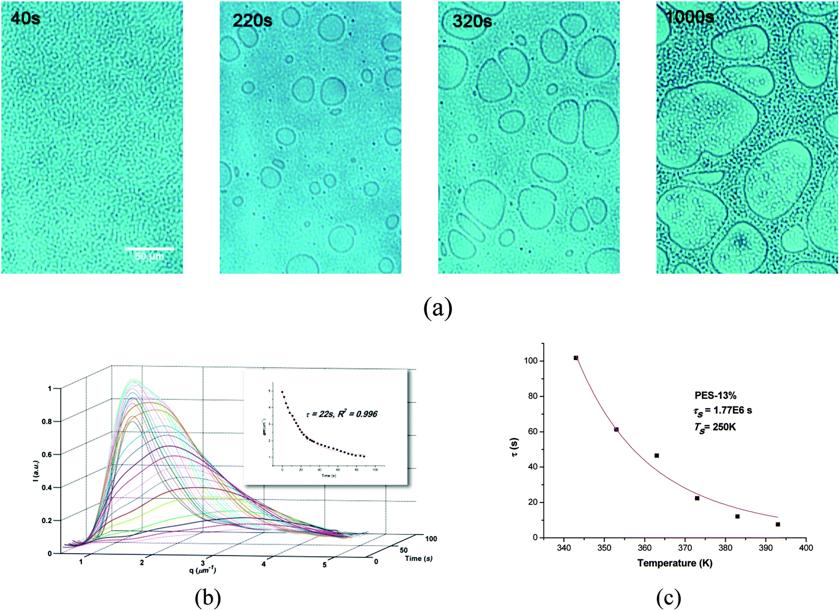 | ||
| Fig. 1 Morphology evolution, light scattering profile, and relaxation time fitted by WLF equation for PES-13% systems. (a) Morphology evolution by OM at 100 °C; (b) TRLS profiles 100 °C (insert: exponential relaxation of qm); (c) the relaxation time versus temperature and fitted by WLF equation. | ||
Light scattering results (Fig. 1b) showed a relaxation behavior of phase size (scattering vector), which also proved the viscoelastic behavior of polymer chains. Due to the presence of dynamic asymmetry between thermoplastics and thermoset precursors in molecular mobility, molecular weight, and glass transition temperatures, the viscoelasticity of the PES-rich phase as slower dynamic phase increased with the escape of the thermoset precursor from the thermoplastic-rich phase and eventually behaved as an elastic body.
As the PES chains disentangle much slower than the phase separation, this causes a mechanical stress with significant influence on the structure evolution:
| ∂i (Πij − σij + pδij) = 0 | (1) |
To study the influence of particle surface properties on the evolution of phase structure, blends filled with both treated and untreated silica were studied. As the size of surface treated and untreated silica are quite close to each other (14 nm and 12 nm, respectively), we therefore deem that surface affinity is the most important factor that differentiates the effect of these two kinds of fillers on phase separation.
Fig. 2 shows the phase structure evolution of samples filled with 5 wt% of treated and untreated nano-sized silica cured at 100 °C. With the addition of particles, the evolution process and phase structure of both samples changed dramatically. Initially, a micro-bicontinuous phase structure was observed in both particle filled blends, which was quite similar to what had been observed in the blend without fillers (PES-13%). However, instead of coarsening rapidly as in PES-13%, both of the PES-rich and epoxy-rich phases in the blends with surface treated and untreated fillers grew quite slowly till the chemical gelation of the epoxy. Eventually bicontinuous networks with much smaller characteristic length scales were obtained in both of two silica filled blends. It seemed that the phase structure evolution and scales of final networks of Tr-14 nm-5% and Un-12 nm-5% were very similar to each other from OM observation.
 | ||
| Fig. 2 Morphology evolution and TEM graphs of epoxy/13 wt% PES blends modified by 5 wt% treated and untreated nano-fillers at 100 °C. (a) OM of Tr-14 nm-5%, (b) OM of Un-12 nm-5%, (c) TEM of Tr-14 nm-5% and Un-12 nm-5%. | ||
To verify the results from OM, the morphology was observed by TEM as shown in Fig. 2c. As one can see, both the silicas of surface treated and untreated were well dispersed in PES phase to form bicontinuous structure. Time-resolved light scattering (TRLS) was also applied to study the phase evolution process. Fig. 3a shows the TRLS profiles of light scattering vector and intensity with time for samples filled with 5 wt% treated or untreated 14 nm (12 nm) silica. A relaxation behavior of phase size change had also been observed by TRLS, however, as one can see, both of the two filled samples had much larger scattering vector qm than that of sample without particles (PES-13% in Fig. 1b). Furthermore, the light scattering vector changed quite little with phase separation as compared with that of PES-13%.
 | ||
| Fig. 3 TRLS profile and WLF equation fitting of Tr-12 nm-5% and Un-12 nm-5%. (a) Intensity versus q during phase separation cured at 100 °C; (b) qmversus phase separation time cured at 100 °C; (c) the relaxation time versus temperature fitted by WLF equation. | ||
Previous and recent works have showed that the evolution of qm corresponds to thermosetting precursor droplets and follows a Maxwell-type relaxation equation (eqn (2)).39,41,44,51
| qm(t) = q0 + A1e−t/τ | (2) |
Both of the two filled samples showed quite similar relaxation time to each other. Furthermore, light scattering profiles of the two samples at other temperatures also showed quite similar tendency.
The temperature dependent relaxation time was well fitted by the Williams-Landel-Ferry (WLF) equation according to previous works:
 | (3) |
Taking C1 = 8.86 K and C2 = 101.6 K, the WLF equation can be written as
 | (4) |
As shown in Fig. 3c, the relaxation time of both treated and untreated samples obeyed the time–temperature superposition principle and could be described well by the WLF equation. The τs values from WLF equation fitting were 1.51 × 10⁷ and 1.54 × 10⁷ for treated and untreated silica filled samples, respectively. Comparing both the τ values at various temperatures and τs values from WLF equation between filled and unfilled systems (Fig. 1), one would find that both surface treated and untreated filler showed clear “enhanced viscoelastic effect” on the PIVPS.
In fact, this kind of similarity in phase separation with meso-fillers of surface treated and untreated systems was also observed when the content of meso-fillers was varied from 0.5 wt% to 5 wt% (which will be discussed in the later part of this article). Combining the results from OM and TRLS, one can easily found that both of the surface treated and untreated silica showed clear “enhanced viscoelastic effect”, while the surface property of particle had limited influence on “enhanced viscoelastic effect” as both phase size and evolution process showed little difference between the two systems with treated and untreated fillers.
It has been found previously that dynamic factors rather than thermodynamics factors are more concerned with the distribution of meso-fillers in the dynamic asymmetry systems during PIVPS process. Compared to PES and epoxy molecules, silica has the lowest mobility and unable to transport in long distance due to the meso-scale size. Even though untreated silica has better affinity with epoxy-rich, the large stress of PES-rich (due to epoxy diffusing) entraps fillers by the entanglements of PES chains with filler surface (as shown in Fig. 2c of TEM graphs). With the distribution of fillers in slow-dynamic phase, the disentanglement of PES chain becomes more difficult due to the hindrance of meso-fillers, which further blocks the migration of meso-fillers to epoxy-rich phase.
As a result, dynamic asymmetry between the fast and slow components makes surface affinity of meso-fillers a minor factor during PIVPS process, while the entangled meso-fillers of both surface-treated and untreated further enlarge the dynamic asymmetry by distributing in and hardening the slow component-rich phase. From this point, one can infer that surface affinity is not the deciding factor that affects the “enhanced viscoelastic effect” of meso-fillers.
3.2 Effects of filler size on phase separation
As the surface affinity showed limited effect on the viscoelastic phase separation, we would anticipate that other factors, like filler size, might have great influence on PIVPS.To study the influence of filler size on the viscoelastic phase separation, three kinds of untreated silica, which primary size are around 12 nm, 100 nm, and 2 μm, respectively, were used to modify the PES/epoxy phase separation system. For easy comparison, the content of particle was first selected as 2 wt% for all the samples.
The phase structure of sample Un-2 um-2% was very similar to that of the sample without any particles (OM results, seen in Fig. 4). When the fillers are 100 nm-size, epoxy-rich macro-phase domains dispersed in the PES-rich matrix were still formed but with smaller size, which means that the coarsening of epoxy-rich phase were somehow hindered. With 2 wt% 12 nm-size silica added, the final phase structure changed to bicontinuous networks with much smaller characteristic length scale instead of macro-phase domains of epoxy-rich structure in Un-2 um-2%. Clearly, the morphology evolution was hindered more significantly with the addition of fillers with smaller size.
 | ||
| Fig. 4 Morphology evolution of blends with 2 wt% of different sized fillers at 100 °C. (a)Un-2 um-2%, (b)Un-100 nm-2%, (c) Un-12 nm-2%. | ||
TRLS results further demonstrated the OM observation. As shown in Fig. 5, the TRLS profiles showed different relaxation behaviors of phase separation process due to the effect of filler size (Fig. 5a). The final qm value increased with the decrease of filler size, which verified the OM observations of smaller characteristic length scale with finer fillers.
 | ||
| Fig. 5 TRLS profiles of samples with 2 wt% of different sized fillers. (a) Intensity versus q at different times; (b) qmversus time; (c) relaxation time versus temperature and fitted by WLF equation. | ||
The evolution of qm also fitted the Maxwell-type relaxation equation (eqn (2)) very well. The larger relaxation time with smaller fillers means that the relaxation of the thermoplastic slows down more significantly. Similar TRLS profiles were exhibited at all temperatures for the samples. All the samples can be fitted quite well by the WLF equation (Fig. 5c). The temperature dependent relaxation times were listed in Table 2. It can be observed that the viscoelastic features of the phase separation did not change with the addition of different size of particles, while the “enhanced viscoelastic effect” got more significant with the decrease of filler size at the same content (Table 3).
| Samples | Relaxation time (s) | τ s/s | T s/K | |||||
|---|---|---|---|---|---|---|---|---|
| 343 K | 353 K | 363 K | 373 K | 383 K | 393 K | |||
| PES-13% | 102 | 61 | 47 | 22 | 12 | 8 | 1.77 × 10⁶ | 250 |
| Un-12 nm-2% | 524 | 199 | 102 | 56 | 37 | 14 | 6.81 × 10⁶ | 273 |
| Un-100 nm-2% | 374 | 151 | 85 | 40 | 21 | 7 | 5.50 × 10⁶ | 272 |
| Un-2 um-2% | 140 | 73 | 37 | 19 | 11 | 8 | 2.03 × 10⁶ | 253 |
| Samples | Relaxation time (s) | τ s/s | T s/K | |||||
|---|---|---|---|---|---|---|---|---|
| 343 K | 353 K | 363 K | 373 K | 383 K | 393 K | |||
| Un-12 nm-0.5% | 113 | 63 | 45 | 22 | 14 | 8 | 1.90 × 10⁶ | 253 |
| Un-12 nm-1% | 439 | 162 | 96 | 49 | 21 | 13 | 5.98 × 10⁶ | 271 |
| Un-12 nm-5% | 992 | 587 | 293 | 146 | 61 | 36 | 1.40 × 10⁷ | 284 |
| Un-100 nm-0.5% | 106 | 58 | 47 | 20 | 12 | 7 | 1.78 × 10⁶ | 250 |
| Un-100 nm-1% | 226 | 117 | 68 | 43 | 21 | 13 | 3.21 × 10⁶ | 272 |
| Un-100 nm-5% | 650 | 383 | 147 | 92 | 43 | 25 | 1.18 × 10⁷ | 280 |
| Un-2 um-0.5% | 128 | 63 | 36 | 24 | 13 | 7 | 2.02 × 10⁶ | 252 |
| Un-2 um-1% | 140 | 73 | 37 | 19 | 11 | 8 | 2.21 × 10⁶ | 254 |
| Un-2 um-5% | 131 | 55 | 35 | 23 | 11 | 5 | 2.00 × 10⁶ | 252 |
For meso-fillers of various sizes, one can image that the specific surface area increases quickly with the decrease of filler size, which should provide much more entangle points with slow-dynamic phase (PES-chains) during PIVPS, and thus enlarges the dynamics asymmetry. If it is true, i.e., large surface area of meso-fillers favors “enhanced viscoelastic effect”, increase the content of fillers (at same level of filler size) would also enlarge the enhancement effect.
3.3 Effects of filler content on phase separation
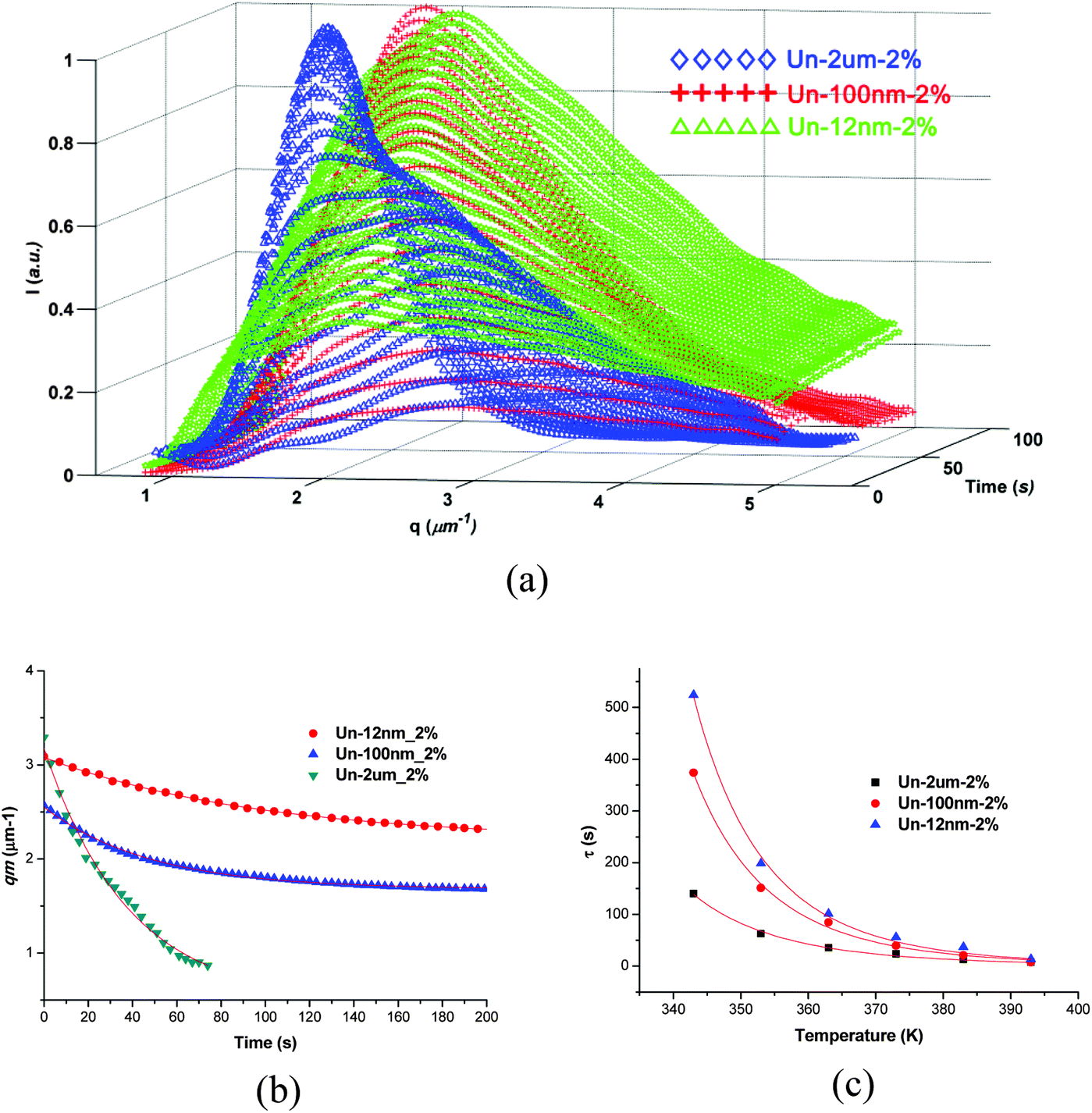
To verify the point mentioned above, we studied the influence of filler content on the enhanced viscoelastic effect by changing the content of fillers with various diameters. As shown in Fig. 6, the phase separation was affected greatly by the filler content for all the fillers. The characteristic length scale of phase structure decreased with the increase of filler content; moreover, this tendency was much more profound for systems with lower size fillers. | ||
| Fig. 6 OM observations of phase structure of samples at the final stage of curing with fillers of different contents and sizes. | ||
For the blends modified with 12 nm untreated fillers, with the addition of 1 wt% filler, the phase structure became much smaller than the PES/epoxy blend without fillers. However, the phase structure only changed slightly with the increase of filler content for 2 um-sized filler added systems, the epoxy domains still dispersed in PES matrix with the addition of even 5 wt% 2 um-size fillers. The effect of 100 nm fillers was located between 12 nm and 2 um fillers.
The TRLS profiles once more showed the same trend with the OM results (seen in Fig. 7). The qm value was strongly affected by the content of nanoscaled fillers, but changed slightly with micron-sized fillers.
 | ||
| Fig. 7 TRLS profiles of samples with fillers of different contents and sizes. | ||
Compared to the micron fillers, the nano-scaled fillers have much larger specific surface area; as a result, increasing the content of nano-fillers would enlarge the total surface area of fillers greatly, while the surface area of micron-fillers still keeps in a much lower level even though their content is also increased several times.
At this stage, it seems that surface area is the dominate factor deciding the “enhanced viscoelastic effect” of meso-fillers on PIVPS. On the basis of this idea, we can expect that the change of phase morphology occurred at low content of nanoparticle could also be achieved for systems with higher content of larger sized fillers when their surface area are comparable.
3.4 Effect of surface area
To demonstrate the equivalent effect of size and content of meso-fillers on the “enhanced viscoelastic effect” due to surface area, we compared all the fillers in both size and content in order to get a relationship between their surface area and the characteristic phase separation behavior.The morphology observed by SEM of all the samples studied was compared as shown in Fig. 8. As one can observe from these graphs, epoxy-rich domains dispersed in PES-rich matrix and formed in all the systems, while the dimension of epoxy-rich domains is strongly related to the enhanced viscoelastic effect of fillers.
 | ||
| Fig. 8 SEM micrographs of samples after cured at 100 °C for 2 h and postcured at 150 °C for 5 hours. | ||
The phase structure of blends modified by both treated and untreated nano-sized silica was very similar to each other at all contents of fillers, which indicated that the filler surface property has little influence on the “enhanced viscoelastic effect”. Phase structures with smaller characteristic length scale were obtained with the increasing of filler content and reduction of filler size, in other words, phase structure shifted to smaller size with the increase of filler surface area, which was caused by the entanglement of filler surface with PES chains.
With the increase of filler size, the dimension of phase structure enlarged quickly, while the content growth reversed this tendency. Taking the morphology of Un-100 nm-2% as an example, its phase size was approximate between that of Un-12 nm-0.5% and Un-12 nm-1%; while the morphology of Un-12 μm-5% was somewhat similar to that of Un-100 nm-0.5%. With consideration of the surface area of fillers, we can roughly attribute the similarity of phase dimension to their comparatively same level of surface areas for the added fillers.
To make this kind of similarity in visual inspection more accurate, we calculated the total surface area of filler (per gram of samples) and plotted with the characteristic relaxation of phase separation time at various temperatures (as shown in Table 2).
As can be seen from Fig. 9 (samples at 80 and 90 °C were given as examples), the total surface area of fillers, including both nano-scaled and micron-sized fillers, roughly showed a linear relationship with the characteristic relaxation of phase separation time. In consideration of the disperse variations of fillers in precursor solutions, one can find that the linear relationship is rational.
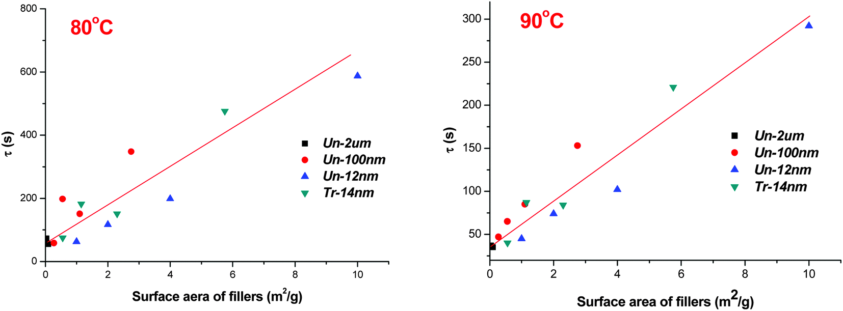 | ||
| Fig. 9 Dependence of relaxation times on filler surface areas (per gram of samples) at 80 °C and 90 °C. | ||
Combining the above experimental work and data processing, we can interpret that the effect of fillers on the PIVPS is mainly resulted from the chain entanglement of slow dynamic part with filler surface. During PIVPS, the chain mobility of slow dynamic part is much lower compared to the phase separation time, while the sharply increased mechanical stress from phase separation, as well as from deep quench, makes it impossible for the disentanglement of slow-dynamic polymer chain from the filler surface even though there might have less interaction points between polymer chains and un-affinity filler surface (like untreated silica). The fast diffusion of precursors deteriorates this situation and presses more slow-dynamic polymer chains onto filler surface, as a result, fillers show an “enhanced viscoelastic effect” on the PIVPS due to their surface interactions with slow dynamic polymer chains.
3.5 Glass transition behaviors with fillers
To confirm the above discussions of the influence of filler surface, size, and content on the “enhanced viscoelastic effect”, dynamics mechanical analysis was carried out to study the viscoelastic behavior of glass transition process of the fully cured PES modified epoxy systems. Fig. 10 shows the curves of tan![[thin space (1/6-em)]](https://www.rsc.org/images/entities/char_2009.gif) δ with temperature for all the blends. There were two peaks between 50 °C and 200 °C: the lower one, which was around 120 °C, corresponded to the glass transition temperature of fully cured epoxy-rich matrix, while the higher one represented the glass transition temperature of PES-rich phase.
δ with temperature for all the blends. There were two peaks between 50 °C and 200 °C: the lower one, which was around 120 °C, corresponded to the glass transition temperature of fully cured epoxy-rich matrix, while the higher one represented the glass transition temperature of PES-rich phase.
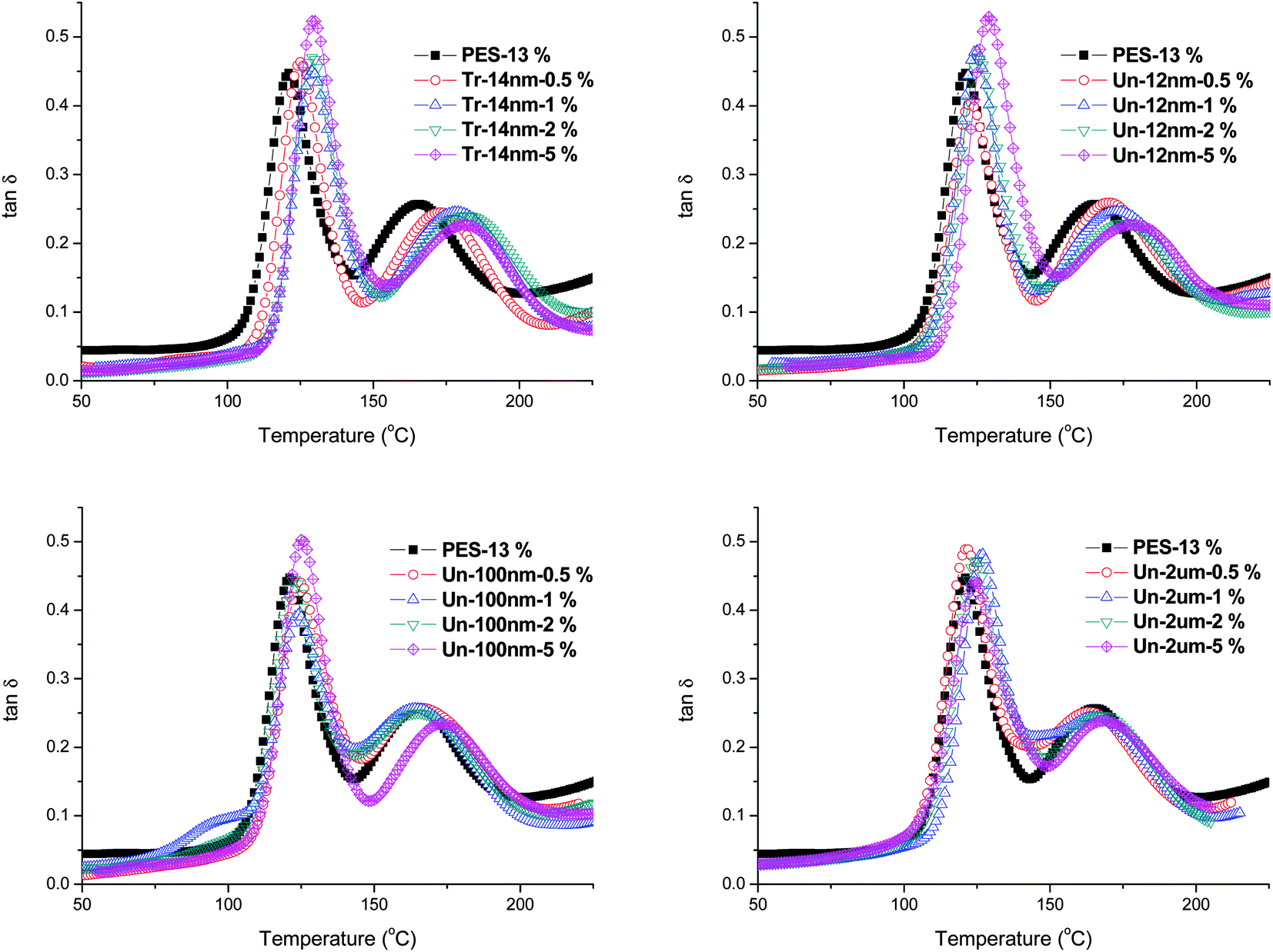 | ||
| Fig. 10 Glass transition process studied by DMA of samples after cured at 100 °C for 2 hours and postcured at 150 °C for 5 hours. | ||
As summarized in Table 4, one can clearly observed the trend of Tg with filler size and content. The glass transition temperatures of both epoxy-rich and PES-rich phases increased with the addition of fillers and their content. Fillers with finer size and larger content (surface area) improved the Tg more significantly.
| Samples | Content | |||||||
|---|---|---|---|---|---|---|---|---|
| T g1/°C | T g2/°C | |||||||
| 0.5 | 1 | 2 | 5 | 0.5 | 1 | 2 | 5 | |
| PES-13% | 121 | 165 | ||||||
| Tr-14 nm | 125 | 128 | 129 | 130 | 173 | 179 | 183 | 181 |
| Un-12 nm | 123 | 125 | 126 | 124 | 170 | 173 | 175 | 173 |
| Un-100 nm | 124 | 124 | 125 | 125 | 171 | 173 | 174 | 175 |
| Un-2 μm | 121 | 123 | 124 | 124 | 168 | 170 | 172 | 174 |
Compared with PES-13%, the addition of fillers hindered the phase separation due to “enhanced viscoelastic effect”, as a result, more PES-chains were blocked into epoxy-rich phase, which increased the Tg of epoxy rich phase with the increase of filler surface area. While for PES-rich, the surface interaction of fillers with PES (entanglement) constrained the rotation of PES-chains, and thus improved the Tg of PES-rich.
As the constrain point increased with entanglement point, large surface area of meso-fillers enhanced the growth of Tg of PES-rich. This kind of chain entanglement of PES with filler surface could also be proved by the volume fraction of constrained region of tan delta from DMA analysis.52 As the filler is dispersed in PES phase, the constrained region was calculated using the height depression of tanδ corresponding to PES-rich phases. The constrained region was calculated by following equation:
 | (5) |
δ peak: | (6) |
The PES constrained region with filler content is list in Table 5 as calculated from Fig. 10. With the increase of filler content and/or the decrease of filler size, there is an increasing trend in PES constrained region as well as the relaxation time of phase separation. When the filler surface area in per gram of samples is relative low, the PES constrained region become very small, and therefore with large deviations (as for 0.5 wt% of filler samples). From the above results, it can be found that fillers with larger surface area would increase the “enhanced viscoelastic effect” during PIVPS due to the incremental chain entanglement points of slow-dynamic part with filler surface.
| Samples | Content | |||
|---|---|---|---|---|
| Constrained regions | ||||
| 0.5 | 1 | 2 | 5 | |
| Tr-14 nm | 0.005714 | 0.003651 | 0.015896 | 0.048896 |
| Un-12 nm | −0.00431 | 0.001367 | 0.017998 | 0.047916 |
| Un-100 nm | −0.00023 | 0.001139 | 0.016596 | 0.030518 |
| Un-2 μm | −0.00971 | 0.006174 | 0.002051 | 0.017297 |
4. Conclusions
The “enhanced viscoelastic effect” of mesoscopic fillers is universal in systems with viscoelastic phase separation independent of filler surface affinity. The slow part (viscous component) is preferential to chain entangle with mesoscopic fillers (on the surface) due to the quick development of phase separation. As a result, there are limited differences for mesoscopic fillers with different surface affinity.Surface area of mesoscopic fillers is the primary factor that influences “enhanced viscoelastic effect”. Large surface area from either finer filler size or larger content provides more entanglement point for filler surface with slow-dynamic part, which blocks the phase separation process and shows more profound “enhanced viscoelastic effect”.
The characteristic phase dimension decreases, while relaxation time of phase separation increases, quickly with the decrease of filler size and/or increase of filler content, i.e., increase of filler surface area. The increase of glass transition temperature and constrained area of tan delta was consistent well with the change in phase separation behavior due to the “enhanced viscoelastic effect” from mesoscopic fillers.
Acknowledgements
This research work was supported by the National Natural Science Foundation of China (Grant 20974027, 21274031), and the Scientific Research Foundation for the Returned Overseas Chinese Scholars, State Education Ministry.References
- J. K. Fink, High performance polymers, William Andrew, Norwich, NY, 2008 Search PubMed.
- Y. Iwashita and H. Tanaka, Nat. Mater., 2006, 5(2), 147–152 CrossRef CAS PubMed.
- M. Jaffe, P. Chen, E.-W. Choe, T.-S. Chung and S. Makhija, in High Performance Polymers, Springer, 1994, pp. 297–327 Search PubMed.
- A. Bonnet, J. P. Pascault, H. Sautereau, M. Taha and Y. Camberlin, Macromolecules, 1999, 32(25), 8517–8523 CrossRef CAS.
- D. P. Fang, C. C. Riccardi and R. J. J. Williams, Polymer, 1993, 34(18), 3960–3961 CrossRef CAS.
- T. Inoue, Prog. Polym. Sci., 1995, 20(1), 119–153 CrossRef CAS.
- P. A. Oyanguren, P. M. Frontini, R. J. J. Williams, G. Vigier and J. P. Pascault, Polymer, 1996, 37(14), 3087–3092 CrossRef CAS.
- R. J. J. Williams, B. A. Rozenberg and J. P. Pascault, Polymer Analysis Polymer Physics, 1997, 128, 95–156 CrossRef CAS.
- E. Girard-Reydet, H. Sautereau, J. P. Pascault, P. Keates, P. Navard, G. Thollet and G. Vigier, Polymer, 1998, 39(11), 2269–2279 CrossRef CAS.
- P. C. Hohenberg and B. I. Halperin, Rev. Mod. Phys., 1977, 49(3), 435 CrossRef CAS.
- J. W. Cahn, J. Chem. Phys., 1965, 42(1), 93–99 CrossRef CAS.
- I. M. Lifshitz and V. Slyozov, J. Phys. Chem. Solids, 1961, 19(1–2), 35–50 CrossRef.
- C. Wagner, Z. Elektrochem., 1961, 65, 581–591 CAS.
- H. Furukawa, Adv. Phys., 1985, 34(6), 703–750 CrossRef CAS.
- H. Tanaka, A. J. Lovinger and D. D. Davis, Phys. Rev. Lett., 1994, 72(16), 2581–2584 CrossRef CAS.
- L. L. He, L. X. Zhang and H. J. Liang, J. Phys. Chem. B, 2008, 112(14), 4194–4203 CrossRef CAS PubMed.
- Y. Li and H. Shimizu, Macromolecules, 2008, 41(14), 5339–5344 CrossRef CAS.
- M. R. Bockstaller and E. L. Thomas, Phys. Rev. Lett., 2004, 93(16), 166106 CrossRef.
- T. Kietzke, D. Neher, M. Kumke, O. Ghazy, U. Ziener and K. Landfester, Small, 2007, 3(6), 1041–1048 CrossRef CAS PubMed.
- J. Gao, C. Huang, N. Wang, W. Yu and C. Zhou, Polymer, 2012, 53(8), 1772–1782 CrossRef CAS PubMed.
- M. J. A. Hore and M. Laradji, J. Chem. Phys., 2008, 128(5), 054901 CrossRef PubMed.
- P. Tian and G. D. Smith, J. Chem. Phys., 2006, 124(18), 184701 CrossRef PubMed.
- V. V. Ginzburg, Macromolecules, 2005, 38(6), 2362–2367 CrossRef CAS.
- A. J. Schultz, C. K. Hall and J. Genzer, Macromolecules, 2005, 38(7), 3007–3016 CrossRef CAS.
- M. Laradji and M. J. A. Hore, J. Chem. Phys., 2004, 121(21), 10641–10647 CrossRef CAS PubMed.
- M. Si, T. Araki, H. Ade, A. L. D. Kilcoyne, R. Fisher, J. C. Sokolov and M. H. Rafailovich, Macromolecules, 2006, 39(14), 4793–4801 CrossRef CAS.
- K. Yurekli, A. Karim, E. J. Amis and R. Krishnamoorti, Macromolecules, 2003, 36(19), 7256–7267 CrossRef CAS.
- Y. W. Cao, J. Zhang, J. C. Feng and P. Y. Wu, ACS Nano, 2011, 5(7), 5920–5927 CrossRef CAS PubMed.
- S. S. Ray and M. Bousmina, Macromol. Rapid Commun., 2005, 26(20), 1639–1646 CrossRef CAS.
- L. T. Vo and E. P. Giannelis, Macromolecules, 2007, 40(23), 8271–8276 CrossRef CAS.
- H. Tanaka, J. Phys.: Condens. Matter, 2000, 12, 207–264 CrossRef.
- H. Tanaka and T. Araki, Chem. Eng. Sci., 2006, 61(7), 2108–2141 CrossRef CAS PubMed.
- H. Tanaka, Phys. Rev. Lett., 1994, 72(23), 3690–3693 CrossRef CAS.
- H. Tanaka, Phys. Rev. E: Stat. Phys., Plasmas, Fluids, Relat. Interdiscip. Top., 1995, 51(2), 1313–1329 CrossRef CAS.
- T. Araki and H. Tanaka, Macromolecules, 2001, 34(6), 1953–1963 CrossRef CAS.
- H. Tanaka, Phys. Rev. Lett., 1993, 71(19), 3158–3161 CrossRef CAS.
- J. Khademzadeh Yeganeh, F. Goharpey and R. Foudazi, RSC Adv., 2012, 2(21), 8116 RSC.
- X. Zhong, Y. Liu, H. Su, G. Zhan, Y. Yu and W. Gan, Soft Matter, 2011, 7(7), 3642–3650 RSC.
- Y. Liu, X. H. Zhong, G. Z. Zhan, Y. F. Yu and J. Y. Jin, J. Phys. Chem. B, 2012, 116(12), 3671–3682 CrossRef CAS PubMed.
- W. J. Gan, Y. F. Yu, M. H. Wang, Q. S. Tao and S. J. Li, Macromolecules, 2003, 36(20), 7746–7751 CrossRef CAS.
- Y. F. Yu, M. H. Wang, W. J. Gan, Q. S. Tao and S. J. Li, J. Phys. Chem. B, 2004, 108(20), 6208–6215 CrossRef CAS PubMed.
- J. Jose, K. Joseph, J. Pionteck and S. Thomas, J. Phys. Chem. B, 2008, 112(47), 14793–14803 CrossRef CAS PubMed.
- P. Jyotishkumar, J. Koetz, B. Tiersch, V. Strehmel, C. Ozdilek, P. Moldenaers, R. Hassler and S. Thomas, J. Phys. Chem. B, 2009, 113(16), 5418–5430 CrossRef CAS PubMed.
- P. Jyotishkumar, C. Ozdilek, P. Moldenaers, C. Sinturel, A. Janke, J. Pionteck and S. Thomas, J. Phys. Chem. B, 2010, 114(42), 13271–13281 CrossRef CAS PubMed.
- S. Goossens, B. Goderis and G. Groeninckx, Macromolecules, 2006, 39(8), 2953–2963 CrossRef CAS.
- S. Goossens and G. Groeninckx, Macromolecules, 2006, 39(23), 8049–8059 CrossRef CAS.
- H. Nakanishi, M. Satoh, T. Norisuye and Q. Tran-Cong-Miyata, Macromolecules, 2006, 39(26), 9456–9466 CrossRef CAS.
- G. Z. Zhan, X. L. Tang, Y. F. Yu and S. J. Li, Polym. Eng. Sci., 2011, 51(3), 426–433 CAS.
- M. Rico, J. López, B. Montero and R. Bellas, Eur. Polym. J., 2012, 48(10), 1660–1673 CrossRef CAS PubMed.
- P. Jyotishkumar, P. Moldenaers, S. M. George and S. Thomas, Soft Matter, 2012, 8(28), 7452–7462 RSC.
- X. H. Zhong, Y. Liu, H. H. Su, G. Z. Zhan, Y. F. Yu and W. J. Gan, Soft Matter, 2011, 7(7), 3642–3650 RSC.
- P. P. Vijayan, D. Puglia, J. M. Kenny and S. Thomas, Soft Matter, 2013, 9(10), 2899 RSC.
| This journal is © The Royal Society of Chemistry 2014 |