
 Open Access Article
 This Open Access Article is licensed under a
 Creative Commons Attribution 3.0 Unported Licence
Direct evidence for an interdiffused intermediate layer in bi-magnetic core–shell nanoparticles†
Amélie
Juhin
*a,
Alberto
López-Ortega
*bc,
Marcin
Sikora
d,
Claire
Carvallo
a,
Marta
Estrader
be,
Sònia
Estradé
fg,
Francesca
Peiró
f,
Maria Dolors
Baró
h,
Philippe
Sainctavit
a,
Pieter
Glatzel
i and
Josep
Nogués
bhj
aInstitut de Minéralogie, de Physique des Matériaux et de Cosmochimie (IMPMC), Sorbonne Universités, UMR CNRS 7590, UPMC Univ Paris 06, Muséum National d'Histoire Naturelle, IRD UMR 206, 4 Place Jussieu, F-75005 Paris, France. E-mail: Amelie.Juhin@impmc.upmc.fr
bICN2 – Institut Catala de Nanociencia i Nanotecnologia, Campus UAB, E-08193 Bellaterra (Barcelona), Spain
cINSTM and Dipartimento di Chimica “U. Schiff”, Università degli Studi di Firenze, Via della Lastruccia 3, Sesto Fiorentino, I-50019 Firenze, Italy. E-mail: lopezortega.alberto@gmail.com
dAGH University of Science and Technology, Faculty of Physics and Applied Computer Science & Academic Centre for Materials and Nanotechnology, Al. Mickiewicza 30, PL-30-059 Kraków, Poland
eDepartament de Química Inorgànica, Universitat de Barcelona, Diagonal 647, E-08028, Barcelona, Spain
fLENS-MIND-IN2UB, Departament d'Electrónica, Universitat de Barcelona, Martí i Franquès 1, E-0828 Barcelona, Spain
gTEM-MAT, CCiT, Universitat de Barcelona, Barcelona, Spain
hDepartament de Física, Universitat Autònoma de Barcelona, E-08193 Bellaterra (Barcelona), Spain
iEuropean Synchrotron Radiation Facility, CS40220, F-38043 Grenoble Cedex 9, France
jInstitució Catalana de Recerca i Estudis Avançats (ICREA), Barcelona, Spain
First published on 5th August 2014
Abstract
Core–shell nanoparticles attract continuously growing interest due to their numerous applications, which are driven by the possibility of tuning their functionalities by adjusting structural and morphological parameters. However, despite the critical role interdiffused interfaces may have in the properties, these are usually only estimated in indirect ways. Here we directly evidence the existence of a 1.1 nm thick (Fe,Mn)3O4 interdiffused intermediate shell in nominally γ-Fe2O3–Mn3O4 core–shell nanoparticles using resonant inelastic X-ray scattering spectroscopy combined with magnetic circular dichroism (RIXS-MCD). This recently developed magneto-spectroscopic probe exploits the unique advantages of hard X-rays (i.e., chemical selectivity, bulk sensitivity, and low self-absorption at the K pre-edge) and can be advantageously combined with transmission electron microscopy and electron energy loss spectroscopy to quantitatively elucidate the buried internal structure of complex objects. The detailed information on the structure of the nanoparticles allows understanding the influence of the interface quality on the magnetic properties.
Introduction
In recent years core–shell (CS) nanoparticles have become increasingly appealing to develop efficient ways to stabilize, functionalize and improve the properties of single-phase nanoparticles. Traditionally shells were developed as protecting layers for the nanoparticles, but it was soon realized that, in fact, they could be used as an active part of the novel structure. This initiated a new, rapidly expanding field in CS nanoparticle synthesis.1–6 Thus, novel families of CS nanoparticles are continuously emerging that exhibit the combination of diverse materials (oxides, metals, organics, semiconductors and so on) with dissimilar properties (e.g., magnetic, optical, catalytic, or biomedical).7–12 The synergetic combination of material characteristics usually leads to multifunctional systems with original or enhanced properties which frequently depend critically on the morphological parameters of the structure. Moreover, the interactions between the core and the shell can be used to further tune the functionalities of the CS systems. Notably, a particularly active field in CS nanoparticles is the study of bi-magnetic CS nanoparticles,13,14 where applications in magnetic recording,15 permanent magnets,16 microwave absorption,17 or biomedical applications7,10,18–20 are currently being developed.Given the critical role of the CS morphology (i.e., core diameter, shell thickness and shape), the constituting materials and their interface in establishing the final properties of the nanoparticles, the precise determination of these parameters is crucial for the understanding and fine tailoring of the functionalities of CS systems. However, this type of characterization is far from simple and often it is only the combination of several characterization techniques that allows solving the CS internal structure. High-resolution transmission electron microscopy (HR-TEM) images, in particular, in combination with electron energy loss spectroscopy (EELS) or energy dispersive X-ray spectroscopy, provide precise local morphological information.21,22 However, typically only a small number of particles can be analyzed, so that averaged properties can be hard to determine. In contrast, conventional diffraction techniques (e.g., small angle X-ray and neutron scattering, SAXS23 and SANS24) allow macroscopic amounts of sample (i.e., millions of nanoparticles) to be studied, but they have only limited chemical selectivity (unless more complex anomalous-SAXS is used25). X-ray spectroscopic techniques such as soft X-ray absorption (XAS), particularly in combination with X-ray magnetic circular dichroism (XMCD) for ferro- and ferri-magnetic systems, can potentially complement the information obtained from other techniques and provide insight into the electronic and magnetic structures of the systems.26–28 Remarkable illustrations are given in, for example, ref. 29–35, where accurate information on site and valence distribution was obtained from soft XAS/XMCD in single-phase ferrite nanoparticles. For multi-phased systems with complex internal structures such as CS nanoparticles, a quantitative analysis using soft XAS and XMCD may however be more challenging since (i) in fluorescence yield detection mode, severe spectral distortion due to self-absorption effects, which are difficult to correct for, often limits a detailed quantitative analysis; (ii) in total electron yield detection mode the probing depth is rather small (60% of the signal comes from the top 2 nanometers)36 and consequently the signal is strongly depth dependent. Nevertheless, valuable internal information can be obtained from soft XAS-XMCD measurements in transmission for sufficiently thin, homogenous structures,37 and even using total electron yield detection by a thorough and careful analysis procedure.38
Recently, it was shown that resonant inelastic X-ray scattering spectroscopy (RIXS) combined with magnetic circular dichroism (RIXS-MCD) in the hard X-ray range can be a valuable alternative to soft X-ray XMCD, when using demanding sample environments (such as liquid or gas cells), or when investigating materials whose surface may not be representative of bulk properties.39 RIXS is a two-photon spectroscopy technique, which probes the same final state configuration as the L2,3 absorption edges when it is performed over the K pre-edge range, however using hard X-ray photons.40 Thus, RIXS-MCD is expected to yield information about magnetic moments similar to soft XMCD combined with the advantages of a hard X-ray probe.39,41 In this work, we investigate the structure of bimagnetic (Fe,Mn)-based CS nanoparticles with appealing magnetic properties that depend on the interdiffusion,26,27 using a combination of structural, imaging, electronic and magnetic probes. RIXS-MCD used at the Fe and Mn K pre-edge combines (i) the chemical selectivity of core spectroscopy techniques, (ii) the bulk sensitivity of hard X-rays, (iii) the possibility to measure a large amount of CS particles, and (iv) the high energy resolution of RIXS spectroscopy.42 RIXS-MCD elucidates the structure of the CS nanoparticles demonstrating unambiguously, not only the presence of a magnetic γ-Fe2O3 core and a Mn3O4 shell, but also evidencing directly the existence of an intermediate interdiffused magnetic shell of Fe-Mn-oxide. Further quantitative analysis is made using the particle size obtained from TEM-EELS measurements, which allows conclusion on the bulk-average thickness of the core as well as the inner and outer shells. Elucidating the detailed internal structure of the particles provides a thorough understanding of the bulk magnetic properties measured by magnetometry and First-Order Reversal Curves (FORC), in particular, of the influence of the interface quality and the origin of magnetic anisotropy.
Results and discussion
Structural and morphological characterization
The CS nanoparticles were synthesized by a seeded-growth approach, where a Mn-oxide layer was grown on pre-synthesized Fe-oxide nanoparticles (seeds). As evidenced by TEM (ESI Fig. S1†) both the CS nanoparticles and the seeds are roughly spherical, although they exhibit some facets and the overall shape of the CS nanoparticles appears more irregular than for the seeds. This procedure leads to seeds and CS nanoparticles with a high degree of monodispersity (particle size distribution less than 10%) and with an average diameter of 10.9(8) nm and 12.8(8) nm, respectively, which allows estimating the thickness of the outer manganese oxide layer to be ∼1 nm.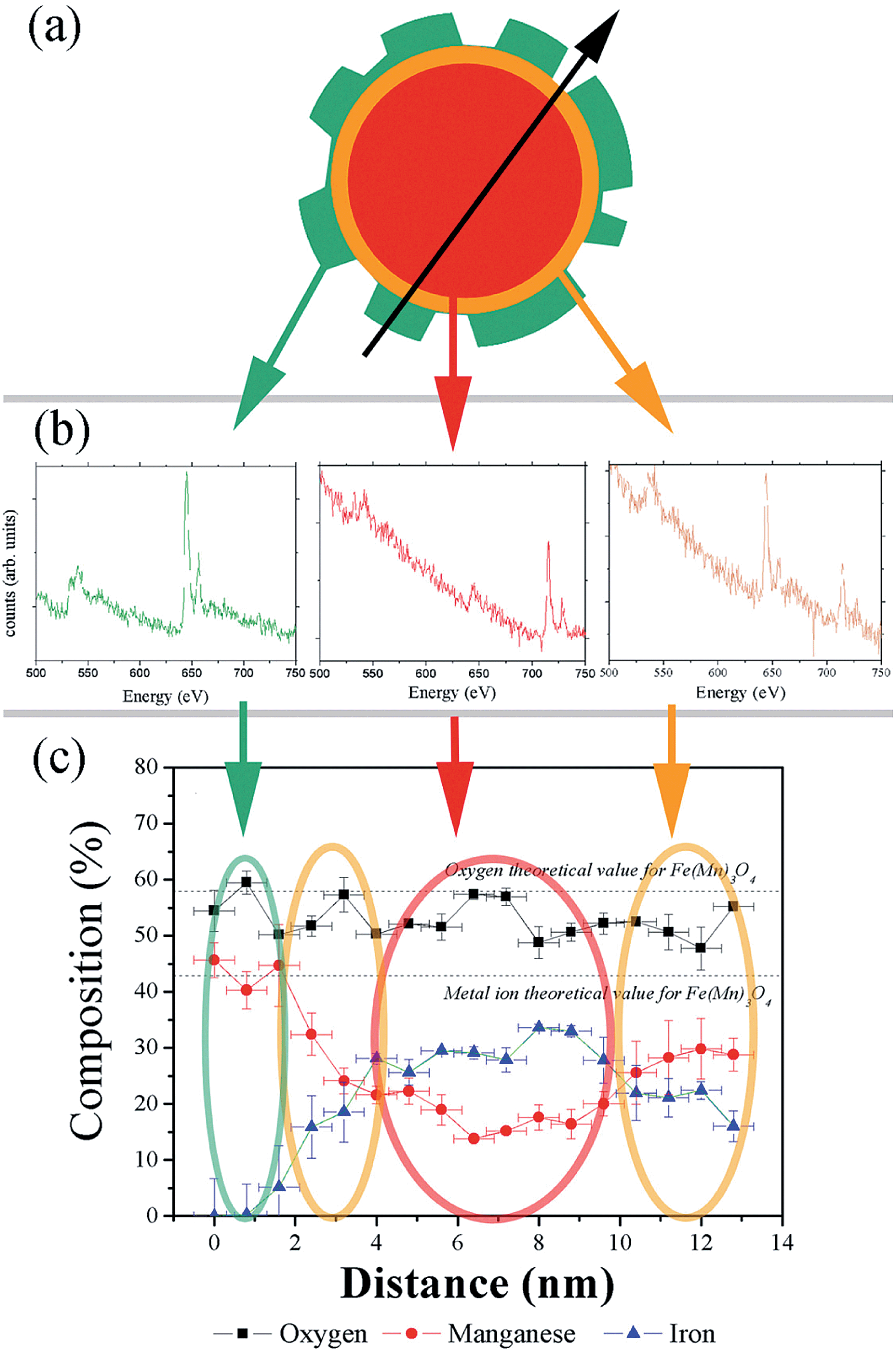 | ||
| Fig. 1 (a) Schematic representation of the irregular shape of a CS nanoparticle (the arrow indicates the direction of the EELS measurements); (b) EELS spectra at three different positions of the particle: core, inner and outer shells; (c) elemental quantification along the particle diameter: Fe (triangles), Mn (circles) and O (squares). | ||
The structural characterization of the CS nanoparticles using Fast Fourier Transform, HR-TEM (ESI Fig. S2a and b†) and powder X-ray diffraction (ESI Fig. S2c†) reveals the presence of a cubic spinel phase, which is compatible with magnetite Fe3O4 or maghemite γ-Fe2O3.43 Additionally, a tetragonal spinel phase is observed, which can be assigned to Mn3O4 or γ-Mn2O3 (ref. 43) and whose relative proportion is small with respect to the cubic phase. The results of the quantitative chemical analysis performed with EELS and averaged across the diameter of a CS nanoparticle (Fig. 1a–c) confirm that the particles are irregular in shape, which can likely be assigned to discontinuous growth of the shell (Fig. 1a). The CS system is probably formed by three different phases. The outer shell, which is about 2 nm thick (at the thickest parts) and highly irregular in shape, maintains a stoichiometry which is closer to manganese oxide (Mn3O4) than to γ-Mn2O3. This is in line with the results of TEM-FFT analysis and XRD. In the central region of the particle, where the composition is roughly constant over a thickness of 6 nm, the spectrum is dominated by the presence of iron ions although a weaker signal attributed to manganese atoms is also detected. This is unavoidable since the electron beam goes through the whole particle, i.e., both the core and the shell(s). Thus two possibilities can be considered for the composition of the core: either the core is formed by solely iron oxide Fe3O4 or γ-Fe2O3 (e.g., the iron cubic spinel phase – in this case, the Mn signal would arise only from the shell) or the core is formed by a mixed manganese iron-rich oxide (MnxFe3−xO4), where diffusion of Mn ions from the shell must have taken place. In both cases, unfortunately, the shape of the shell is too irregular to allow even a semi-quantitative analysis by assuming a spherical symmetry of each layer.21,44 Indeed, the apparent composition of the inner shell covering the entire core depends strongly on its thickness: its chemical composition shows a gradient of iron and manganese ions, with a higher concentration of iron ions close to the core surface, and a higher concentration of manganese ions close to the shell. From the overall analysis, the CS nanoparticles can be described as a core of MnxFe3−xO4 or of iron oxide Fe3−zO4 of about 3 nm in radius (Fig. 1c) surrounded by two different shells: an inner shell formed by a MnxFeyV3−x−yO4 layer (V stands for a vacancy in the octahedral subnetwork) with about 3 nm in thickness and an outer shell of varying thickness (0–2 nm) and composition close to pure Mn3O4.
RIXS-MCD analysis
In order to identify the phases building the inner structure of the particles, RIXS and RIXS-MCD 2D-spectra were recorded at the Fe and Mn K-edges on the CS particles. Additionally, we recorded RIXS and RIXS-MCD spectra at fixed emission energy while scanning the incident energy, i.e., XAS and XMCD one-dimensional spectra using the so-called High Energy Resolution Fluorescence Detection (HERFD). Note that although HERFD-XAS (HERFD-XMCD) spectra might show strong similarities to XAS (XMCD) spectra, significant differences may be observed.42Compared to the TEM-FFT analysis, the added value of EELS and X-ray spectroscopy is obviously the chemical selectivity. However, due to the irregular particle shape, the data available in EELS are not sufficient to allow for a quantitative analysis of the chemical state. Thus, there is strong motivation for using RIXS and HERFD (further combined with XMCD), which will provide valuable average element selective structural and magnetic information on the CS particles. In Fig. 2a the HERFD-XAS data measured at the Fe K-edge on the CS particles and on the seeds used as starting materials are shown. Both spectra are typical for Fe3+-bearing compounds, with a white line located at 7132 eV and a pre-edge at 7113.8 eV. The two broad features visible in the edge are found at the same energy positions (at ∼7140 eV and ∼7148 eV) for the CS particles and for the seeds. This indicates that Fe ions occupy similar sites in either the CS or the seed, which is compatible with the scenario of the CS particle core being built from the seed. However, the existence of spectral differences, such as, for the CS, the absence of the two shoulders below and above ∼7125 eV, also shows that a fraction of the core has undergone structural transformations, leading to a new phase not present in the seeds. For both samples, the pre-edge region shows a well-resolved pronounced single feature, as in the case of Fe3O4 and γ-Fe2O3,45 in which the dominant contribution arises from high spin tetrahedral Fe3+ due to the existence of intense electric dipole allowed transitions.46 This suggests that in the seed and CS samples, the dominant contribution arises also from high spin tetrahedral Fe3+. However, an analysis based solely on the HERFD-XAS spectra may be misleading, since the relative spectral intensities are highly dependent on the emission energy chosen.42 The RIXS-MCD plane measured at the Fe K-edge in the seeds (Fig. 3a) provides a more complete view, since it is a 2D plot of the XMCD features as a function of both the incident energy and the energy transfer. Two peaks with opposite signs are visible in the region of the Kα1 emission (i.e. with an incident energy of ∼7113.6 eV and energy transfer of ∼709 eV and ∼710 eV respectively) and with a normalized peak-to-peak intensity of ∼16%, which is the spectral signature of tetrahedral Fe3+.39 Comparison with the RIXS-MCD plane measured for Fe3O4 (ESI Fig. S5†) unambiguously evidences the absence of Fe2+ in the seeds (no features are visible around ∼707 eV energy transfer and ∼7112 eV incident energy), which are therefore mainly composed of γ-Fe2O3. The HERFD-XMCD spectrum (Fig. 2b) is a cut of the RIXS-MCD plane along the diagonal direction with the emission energy fixed here at 6403.7 eV; it is a derivative-like signal obtained from the 1D projection of the double feature visible on the RIXS-MCD plane. The existence of a detectable MCD signal for the CS particles evidences that they contain Fe-bearing ferrimagnetic phases. The similarity of the HERFD-XMCD spectra recorded under the same conditions for the CS particles and the seeds, both in shape and intensity (in particular, the absence of a shoulder at 7112 eV), indicates that maghemite γ-Fe2O3 is most likely the major Fe-bearing, magnetic phase building the CS particles (i.e., the core). The slight decrease in MCD intensity for the CS with respect to the seeds might be explained by the presence of a magnetic mixed Fe-Mn-oxide with less tetrahedral Fe3+ than in the seeds, or by the presence of a non-magnetic Fe-bearing phase. However, from the Fe K-edge data alone quantification is difficult, thus the composition of the inner/outer shell cannot be accurately determined.
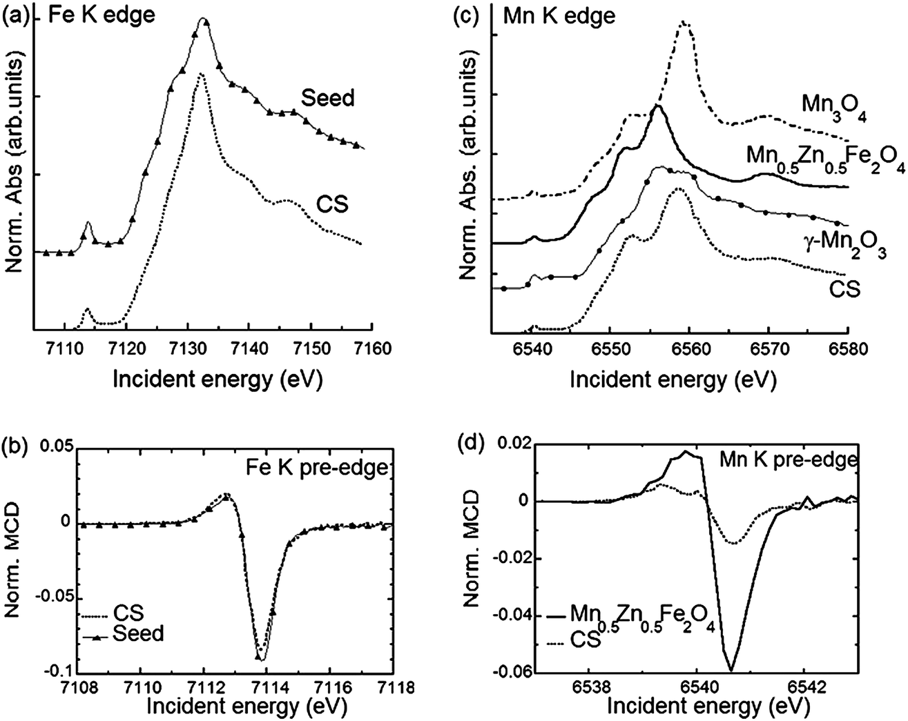 | ||
| Fig. 2 (a) HERFD-XAS spectra recorded at the Fe K-edge using the maxima of Kα1 emission line for the CS nanoparticles (dashed line) and the seeds (dashed line with triangles – note that symbols are plotted every twenty experimental points). (b) Kα1-detected HERFD-XMCD spectra recorded at the Fe K edge for the CS particles and the seeds. The spectra are normalized to the HERFD-XAS pre-edge maximum. (c) HERFD-XAS spectra recorded at the Mn K-edge using the maximum of Kα1 emission for the CS particles (dashed line) and reference samples: Mn3O4 (dash dotted line), Mn0.5Zn0.5Fe2O4 nanoparticles (solid line) and bulk γ-Mn2O3 (solid line with circles). (d) HERFD-XMCD spectra recorded at the Mn K-edge for the CS nanoparticles and the Mn0.5Zn0.5Fe2O4 sample. The spectra are normalized to the HERFD-XAS pre-edge maximum. | ||
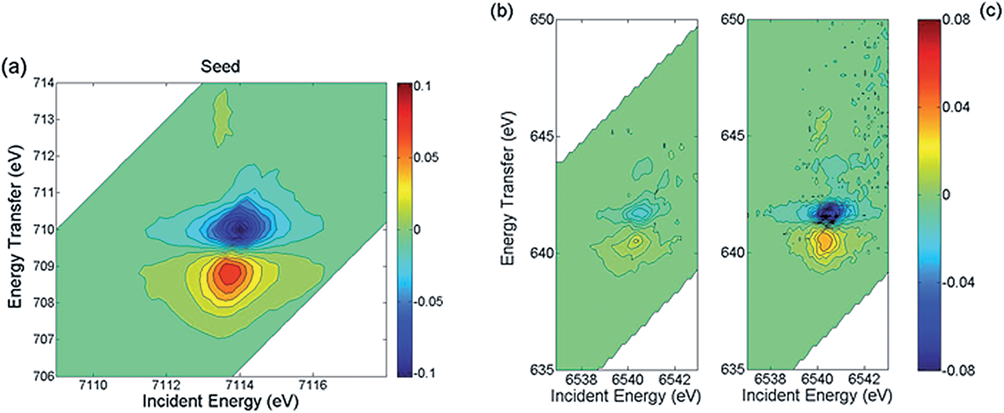 | ||
| Fig. 3 (a) RIXS-MCD spectrum recorded at room temperature at the Fe K pre-edge for the seed. RIXS-MCD spectra recorded at room temperature at the Mn K pre-edge for (b) CS particles and (c) Mn0.5Zn0.5Fe2O4 particles. | ||
Further insight into the structure is provided by the data measured at the Mn K-edge. In Fig. 2c the HERFD-XAS spectrum recorded for the CS particles is compared to those of three reference samples, Mn3O4, γ-Mn2O3 and (Mn,Zn) ferrite nanoparticles with composition close to Mn0.5Zn0.5Fe2O4 and a mean diameter of 18.7 nm (see Methods). The latter are in line with previously published Mn K-edge spectra in similar systems.47,48 Therefore Mn0.5Zn0.5Fe2O4 was used as a reference for tetrahedral Mn in magnetic ferrite nanoparticles, consistent with the findings of ref. 47 where divalent Mn ions essentially occupy the spinel tetrahedral sites. Our results evidence that the main Mn-bearing phase in the CS has a composition close to Mn3O4, which is in agreement with the EELS results, suggesting that the outer shell is composed of Mn3O4. Additionally, the intensity ratio between the peaks at 6552 eV and 6559 eV is slightly higher for the CS particles compared to the Mn0.5Zn0.5Fe2O4 sample, which suggests the possible existence of another phase. This is confirmed by the clear RIXS-MCD signal that is observed for the CS particles at the Mn K-edge (Fig. 3b). Indeed, the fact that a signal is detected evidences directly and unambiguously that a Mn-bearing magnetic phase is present in the sample, and that it is sufficiently abundant, crystallized and magnetically ordered to be detected at room temperature. Considering that Mn3O4 and γ-Mn2O3 are paramagnetic at room temperature (TC = 43 K for Mn3O4 and TC = 40 K for γ-Mn2O3),43 the existence of a mixed Fe-Mn spinel is thus strongly supported. The RIXS-MCD plane for the CS is compared to the one measured for Mn0.5Zn0.5Fe2O4 (Fig. 3c), which contains only tetrahedral Mn2+. Apart from the difference in intensities, both planes exhibit at the same energies two MCD features with opposite signs, which indicate that Mn2+ is present in the spinel phase building the inner shell of the CS particle.
In addition to the clear identification of the presence of a new phase, we now exploit the intensity measured in RIXS-MCD to quantify the respective size of the different layers building the CS particle. More precisely, we use the peak-to-peak intensity of the HERFD-XMCD measured at the Fe K-edge (Fig. 2b) and at the Mn K-edge (Fig. 2d) for the CS particles and the other compounds. We consider a simplified model (ESI Fig. S6†) to obtain an estimate of the morphology where we assume that (i) all particles are identical (thus, average quantities will be extracted from the analysis), (ii) the three layers (core of maghemite γ-Fe2O3, inner shell of (MnxFeyV3−x−y)O4, and outer shell of Mn3O4) are arranged in a spherical “onion-like” structure with respective volumes Vcore, Vinner and Vouter, and (iii) the intensity of HERFD-XAS and HERFD-XMCD is dominated by the tetrahedral sites, whose individual contribution is assumed to be ∼4–5 times more intense than the one of the octahedral sites, due to the existence at the K pre-edge of the intense dipole allowed transitions in tetrahedral symmetry.49 Indeed, in the K pre-edge region the contribution of tetrahedral sites dominates the XAS spectrum over that of octahedral sites, since the lack of inversion centre in Td symmetry allows electric dipole transitions, which are more intense than electric quadrupole contributions. The formation of an intermediate layer can be justified as a way to stabilize the cubic-tetragonal lattice parameters (see ESI†).26,43 The composition of the inner shell is very likely to be a gradient between Mn3O4 and γ-Fe2O3 due to cation interdiffusion between both oxides, rather than having a definite composition. This is all the more likely as the conditions of its formation are far from equilibrium. For further quantitative analysis, we therefore assume that the inner shell has an average intermediate composition of (Fe,Mn)3O4, where Fe and Mn ions are both distributed amongst the crystallographic sites, i.e., with 0.5 ion in the tetrahedral site versus 1 ion in the octahedral site.
The peak-to-peak intensity of the HERFD-XMCD data measured at the Mn edge for the CS and Mn0.5Zn0.5Fe2O4 particles provides a relation between Vinner and Vouter (eqn (S3) in ESI†) while the peak-to-peak intensity of the HERFD-XMCD data measured at the Fe edge for the CS and the maghemite [Fe3+]tetra[Fe3+5/3]octaO4 particles provides a relation between Vcore and Vinner (eqn (S6) in the ESI†). By solving these equations using the size of the CS particle determined from the particle size histogram (radius = 6.4 nm, see ESI Fig. S1†), one derives the radial distribution of the three layers between the center and 6.4 nm: 0 ≤ core ≤ 5.0 nm ≤ inner shell ≤ 6.1 nm ≤ outer shell ≤ 6.4 nm. This implies a 5.0 nm radius γ-Fe2O3 core, a 1.1 nm thick (Fe,Mn)3O4 inner shell and a 0.3 nm thick Mn3O4 outer shell.
TEM-EELS and RIXS-MCD shall be regarded as complementary techniques to obtain the structure of core–shell nanoparticles. On the one hand, it should be taken into account that due to the time consuming measuring process, the EELS analysis is commonly based on a small number of particles, while RIXS-MCD gives a microscale average picture which might slightly differ from that obtained at the nanoscale. Consequently, RIXS-MCD achieves a more direct assessment of the overall average composition of the sample. In addition, it directly evidences the existence of the inner shell due to its sensitivity to phases showing a net magnetic moment such as ferri/ferromagnetic phases. On the other hand, the quantitative analysis of RIXS-MCD relies on TEM-EELS results: (i) the average size of the particles is obtained from TEM analysis and (ii) constraints on the composition of the inner shell are provided by the EELS profile averaged over a few particles. In that prospect, the combination of RIXS-MCD and EELS appears highly valuable, providing complementary pictures of the same object, though at different scales.
Temperature and field dependence of the magnetization
The three-layer onion internal structure of the CS particles elucidated by TEM-EELS and RIXS-MCD enables to interpret the results obtained on the bulk magnetic properties from magnetometry and FORC measurements. At high temperatures the zero field cooled (ZFC)/field cooled (FC) magnetization curves of the CS particle (Fig. 4a) exhibit the typical features of the superparamagnetic (SP) blocking temperature, TB = 195 K, while at low temperature, a second transition at about T = 40 K is also observed. On the other hand, the seeds (Fig. 4a) exhibit a single blocking transition at TB = 155 K. The kink at low temperatures can be related to the known Curie temperature of Mn3O4, TC ∼ 40 K,43 while the high temperature features correspond to core–inner shell magnetism.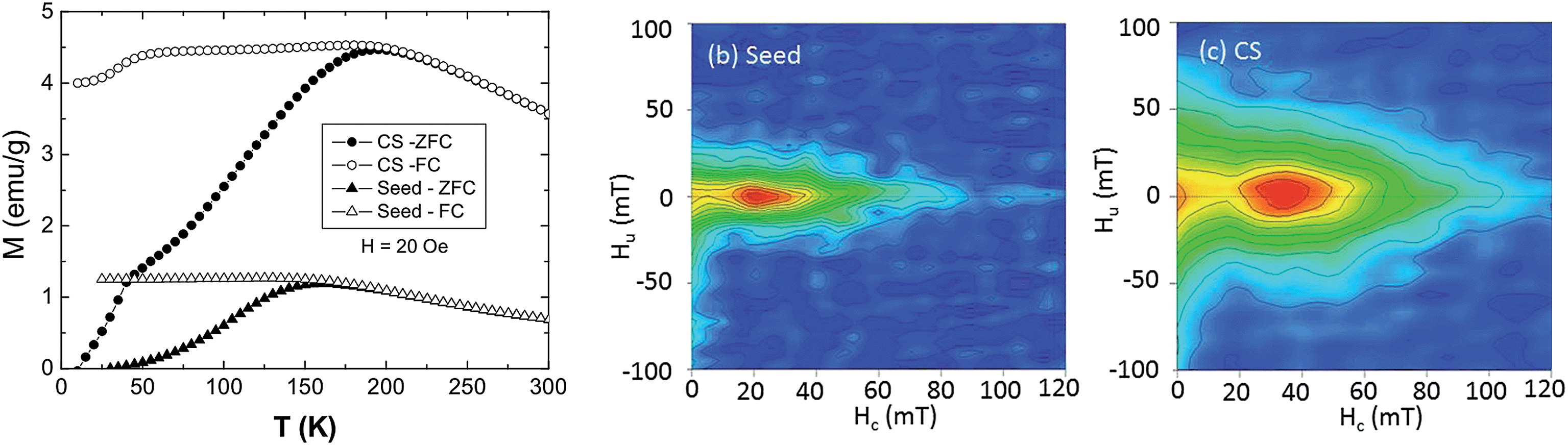 | ||
| Fig. 4 (a) Temperature dependence of the magnetization under FC and ZFC conditions for the CS and the seed nanoparticles. FORC diagrams obtained at 20 K for: (b) seed sample; (c) CS sample. In order to help comparison, the horizontal and vertical scales are identical for both samples. | ||
Since TB = KV/25 kB,50 (where K is the magnetic anisotropy constant, V is the volume and kB is the Boltzmann constant), the increase of TB of the CS nanoparticles with respect to the seeds can be attributed either to the volume increase due to the growth of the inner shell and/or to the possible increase of K. Interestingly, the downturn of M at low temperatures (Fig. 4a) implies an antiferromagnetic coupling between the core and the shell magnetizations.27 However, when compared with nanoparticles with similar size and morphology but with sharp interfaces,27 it can be seen that the drop of M at TC (Mn3O4) is smaller and TB is larger. Both features are consistent with some Fe-Mn intermixing at the interface. Namely, the Mn3O4 counterpart (with low MS and low TC) is reduced, creating a FeMn-oxide with higher MS and TC. On the other hand, similar CS nanoparticles but with a fully interdiffused interface exhibit a ferromagnetic interface coupling.26 Thus, since the antiferromagnetic interface coupling is rather sensitive to the interface quality,27 the magnetic results indicate that the current particles should have only a rather limited interdiffusion, as shown by the RIXS-MCD analysis.
The hysteresis loops measured for both CS and seed nanoparticles (ESI Fig. S3†) show that the coercive field for the seeds is around two thirds of the one for the CS, which indicates that the CS nanoparticles are magnetically harder than the seeds. The saturation magnetization for the seeds is larger than the one for the CS, which can be quantitatively understood from the structural model previously determined. Indeed, from the saturation magnetization MS measured from the seeds (65 emu g−1) and for the Mn3O4 reference samples (35 emu g−1) and assuming the nominal structure γ-Fe2O3 (5.4 nm radius)/Mn3O4 (1.0 nm thickness), one would obtain a MS value of 53 emu g−1 for the CS sample. Since the measured MS value of the CS sample is actually smaller (43 emu g−1), this implies that the γ-Fe2O3 core (with a large MS) should be smaller, which is consistent with the presence of an intermixed intermediate layer with lower MS. More quantitatively, using an estimate of the contribution from the (Fe,Mn)3O4 shell (see Methods) and the quantitative model extracted from RIXS-MCD, one computes that the saturation magnetization should be about 46 ± 5 emu g−1 for the CS nanoparticles, which is in line with what is in fact measured for the CS sample. Moreover, comparing the current CS nanoparticles with similar ones with sharp interfaces,27 it can be seen that the coercivity HC of the latter is considerably larger (HC (sharp-interface) ∼ 600 Oe) than the one of the current CS nanoparticles (HC (CS) ∼ 340 Oe), as expected for core–shell nanoparticles with a slightly interdiffused interface. This is once more consistent with the thickness reduction of the Mn3O4 shell, since HC in strongly exchange coupled hard-soft systems is directly linked to the volume fraction of the hard phase, HC ≈ 2(fhardKhard + fsoftKsoft)/(fhardMhard + fsoftMsoft), where f is the volume fraction of the soft and hard phases, with fhard = 1 − fsoft.51
First order reversal curve diagrams
FORC diagrams were obtained at 20 K on the CS and the seed samples in order to provide information about the coercivity distribution and interaction field distribution.52–54 The FORC diagram obtained at 20 K for the CS sample (Fig. 4b) is characterized by two peaks, one close to the origin of the diagram, corresponding to SP grains, and the other one on the horizontal axis, centered at a coercivity HC around 40 mT, corresponding to the grains that are stable single-domain (SSD). The main difference in the FORC diagrams is the position of the SSD peak, centered at higher HC for the CS (40 mT) than for the seeds (∼20 mT), as evidenced also in the hysteresis loops (ESI Fig. S3†). As discussed above, this arises from the strong exchange coupling between the soft core and the hard shell which leads to a HC determined by the relative amount of hard/soft phases.51 However, the small increase in HC with respect to the seeds indicates that the hard shell is rather thin, which is consistent with the formation of an intermediate shell with somewhat low anisotropy. Moreover, the SSD peak of the CS sample is considerably broader along the abscissa than the one of the seeds. This is also an indication of a broader distribution of switching fields as expected from a hard–soft coupling. In fact in continuously graded anisotropy thin films the FORC switching field distributions are known to be rather broad.55,56 Hence, the core–shell nanoparticles may be thought of as a gradient anisotropy material with a soft-core/intermediate-inner-shell/hard-outer-shell.Interestingly, the FORC distribution along the ordinate axis is also different for the two samples: the contours for the CS sample are more spread around the vertical axis than for the seed sample, which indicates stronger magnetic interactions (Fig. 4c). This is even more evident when the FORC distributions are normalized (ESI Fig. S4†).57 Namely, the full width at half maximum of the FORC distribution of the CS sample (FWHM = 35 mT) is about twice that of the seed sample (FWHM = 15 mT), independently of the coercivity field at which the profile is taken. Thus, the strong magnetic interactions between the core and the shells of individual CS particles dominate the FORC diagram.
Conclusions
We have combined the recently developed RIXS-MCD magneto-spectroscopic technique, in combination with TEM-EELS, magnetometry and FORC measurements, to elucidate the detailed composition, morphology and magnetic properties of Fe-oxide–Mn-oxide core–shell nanoparticles. The individual signature of an interdiffused inner shell was directly evidenced, for the first time, by RIXS-MCD. Our combined TEM-EELS, RIXS-MCD approach gives a multilayered (onion) γ-Fe2O3 (5.0 nm)/(Fe,Mn)3O4 (1.1 nm)/Mn3O4 (0.3 nm) structure, which enables a quantitative understanding of the bulk magnetic measurements. The simplicity of the RIXS-MCD experiment, where samples can be investigated “as is”, and that of the corresponding analysis demonstrate its great potential as a novel, highly sensitive way to provide bulk-type magnetic information in multi-phased systems. In fact, given the increasing complexity of materials for magnetic devices involving multiple layers composed of dissimilar materials (e.g., read/write heads, sensors, magnetic random access memories) or materials with graded compositions for improved performance (e.g., gradient anisotropy for magnetic recording) RIXS-MCD may prove to be a very powerful tool not only for core–shell nanoparticles but for other advanced magnetic materials exhibiting buried layers.Methods
Synthesis of the CS nanoparticles
The CS nanoparticles were synthesized by a seeded-growth approach, where pre-synthesized Fe-oxide nanoparticles were used as seeds for the growth of the Mn-oxide layer.58 Following Park et al.,59 the Fe-oxide seeds were prepared by adding a given amount of iron (III) oleate and 1 mmol of oleic acid into 36 mL of 1-octadecene. The mixture was heated in Ar under magnetic stirring, with a heating rate of 3 °C min−1, up to 320 °C and kept for 30 min. The slurry was removed from the heating source and allowed to cool down to room temperature. The heterogeneous growth of the manganese oxide layer on the Fe-oxide seeds was carried out by adding 42 mg of initial seeds in a solution containing 0.6 mmol of manganese (II) acetylacetonate, 0.6 mmol of 1,2-hexadecanediol, 0.3 mmol of oleylamine, 0.3 mmol of oleic acid and 40 mL of dibenzyl ether.26,27 The slurry was mechanically stirred and heated, under an Ar controlled atmosphere, with a heating rate of 10 °C min−1, until 200 °C and kept for one hour. The flask was removed from the heating source and cooled down in Ar to room temperature. Both the seeds and the CS nanoparticles were washed by several cycles of coagulation with ethanol, centrifugation at 2000×g, disposal of supernatant solution and re-dispersion in hexane.Structural and morphological characterization
TEM images were obtained using a Jeol-JEM-2010 microscope with a LaB6 filament and a Jeol-JEM-2010F microscope with a field-emission gun operated at 200 kV. The nanoparticles were dispersed in hexane and then placed dropwise onto a holey carbon supported grid. The particle size of the seeds and the CS nanoparticles and its standard deviation were obtained by calculating the number average by manually measuring the equivalent diameters of more than 200 particles from TEM micrographs. EELS spectra were acquired at about every 0.5 nm along the diameter of the nanoparticles at an energy range containing the O-K, Mn-L2,3 and Fe-L2,3 edges, with an energy resolution of 0.8 eV. Mn/O and Fe/O quantification was carried out using the Gatan Digital Micrograph commercial software. The composition profile shown in Fig. 1c is averaged over the data measured for three different particles. XRD patterns were collected using a PANalytical X'Pert Pro diffractometer with Cu Kα radiation. The measurements were carried out in a range of 10–100 2θ in steps of 0.012° and a collection time of 300 s.The composition of the (Mn,Zn) ferrite nanoparticles was analyzed using the Cameca SX50 electron microprobe at the CAMPARIS Facility (Université Pierre et Marie Curie, France) using a 15 kV voltage with a 40 nA beam current. X-ray intensities were corrected for dead time, background and matrix effects using the PAP correction procedure. The standards used were α-Fe2O3, MnO and ZnO. The structural formula obtained for the (Mn,Zn) ferrite particles is Mn0.45Zn0.47Fe2.05O4, which is very close to the expected composition Mn0.5Zn0.5Fe2O4. In ferrites, Mn2+ is known to have a strong preference for tetrahedral position.60 In bulk samples it was found to be 100% tetrahedral.61 In (Mn,Zn) ferrite nanoparticles, divalent Mn ions were found to essentially occupy the spinel tetrahedral sites.47 Therefore in the present work, we assume that Mn2+ is fully tetrahedral in the Mn0.45Zn0.47Fe2.05O4 nanoparticles. We have checked numerically that a small inversion on the Mn2+ ions has only a limited impact on the results presented in this work. For an inversion degree of 20%, the thicknesses of the inner shell and the core change only by 0.06 nm and 0.1 nm respectively.
Resonant inelastic X-ray scattering combined with magnetic circular dichroism
The RIXS and RIXS-MCD experiments were carried out at beamline ID26 of the European Synchrotron Radiation Facility (Grenoble, France). Measurements were performed at room temperature at the Fe and Mn K-edges. In the case where the empty 3d orbitals of the absorber are not hybridized with empty p levels, the two steps involved in the 1s2p RIXS process are the following: (i) the absorption step has a pure electric quadrupole origin, i.e., it starts from the initial state 1s22p63dn to the intermediate state 1s12p63dn+1, and (ii) it is followed by an electric dipole emission, from 1s12p63dn+1 to the final state 1s22p53dn+1. The incident energy was selected using a pair of Si(311) crystals. Higher harmonics were suppressed by three Si mirrors operating in total reflection. The intensity of Mn and Fe Kα emission lines (inelastically scattered beam) was analyzed using a set of four spherically bent Ge(333) and Ge(440) crystals, respectively, arranged with an avalanche photo-diode in the Rowland geometry. The sample was set at 45° with respect to the incoming beam with a scattering angle covering 72–99° in the horizontal plane. The overall resolution was measured to be 1.1 eV. For both Fe and Mn, the 1s2p RIXS planes were recorded as a set of constant emission energy scans over the energies of the Kα1 and Kα2 lines. Additionally, absorption spectra were recorded by setting the emission energy to the maximum of the Kα line (6403.7 eV for Fe and 5899.0 eV for Mn), namely HERFD-XAS. The HERFD-XAS spectra were corrected for self-absorption effects with the program FLUO.62The RIXS-MCD experiments were carried out with the same setup as for HERFD and RIXS, the differences being that (i) the incident beam is circularly polarized (instead of being linearly polarized in the case of HERFD/RIXS), (ii) samples are kept in magnetic saturation. The circular polarization was obtained using a 500 μm thick diamond (111) quarter wave plate set downstream the Si(311) monochromator, with a polarization degree of about 75%. The magnetic field (H = 0.3 T) was generated using a permanent Nd2Fe14B magnet. The RIXS-MCD planes were recorded by reversing the photon helicity after every two constant emission energy scans. The RIXS-MCD and HERFD-MCD spectra were recorded in the region of the Fe and Mn K pre-edge. They were normalized to 100% incoming circular polarization degree and to the pre-edge maximum. As self-absorption corrections were found to be weak in the pre-edge range and that all MCD spectra are normalized to the pre-edge maximum, we assume that self-absorption effects do not impact our analysis.
Magnetic measurements
The temperature dependence of the magnetization, M(T), was measured under field cooled and zero field cooled conditions in H = 20 Oe using a SQUID magnetometer. Hysteresis loops, up to a 70 kOe maximum field, were measured at 10 K after field cooling in H = 20 kOe from room temperature using a SQUID magnetometer.The saturation magnetization at 10 K and 4 T are found to be 35 emu g−1 for Mn3O4, 62 emu g−1 for Zn0.5Mn0.5Fe2O4 and 65 emu g−1 for the seeds. The intermediate shell has a composition of (Fe,Mn)3O4 where the tetrahedral sites are all occupied by either Mn(II) or Fe(III) ions. From comparison with Mn0.5Zn0.5Fe2O4, where half of tetrahedral sites are occupied by Zn(II) ions, one expects that the saturation magnetization for this shell would be approximated by 62 emu g−1 × (5/7.5) ≈ 41 emu g−1. However this value is likely to be overestimated: indeed, for Mn0.5Zn0.5Fe2O4, a simple Heisenberg model gives 7.5 Bohr magneton/formula unit (i.e. 177 emu g−1), which is approximately a factor of 2.85 larger than what is actually measured (i.e. 62 emu g−1). Therefore for the (Fe,Mn)3O4 shell, we estimate its contribution to be in between 41 emu g−1 and 15 (≈41/2.85) emu g−1.
First-order reversal curve diagrams were obtained on the CS and the seed samples at the Centre Européen de Recherche et d'Enseignement des Géosciences de l'Environnement in Aix-en-Provence, France, using a Princeton Measurements Corporation Vibrating Sample Magnetometer (VSM), at 20 K and 60 K. One hundred FORCs were used to calculate the FORC diagrams using the FORCInel program.63 Diagrams were plotted with a smoothing factor of 5.
Acknowledgements
AJ thanks T. Allard for help with the microprobe. A.J. and C.C. acknowledge P. Rochette (CEREGE) for help during the FORC measurements. The ESRF is acknowledged for provision of beamtime. C. Mazzoli and ID26 staff are thanked for their help in setting up the Quarter Wave Plate. This work has been supported by the 2014-SGR-1015 and 2009-SGR-35 projects of the Generalitat de Catalunya, by the MAT2010-20616-C02 and MAT2010-16407 projects of the Ministerio de Economía y Competitividad (MINECO). MS acknowledges support from the Polish Ministry of Science and Higher Education. ME acknowledges the Spanish Ministry of Science and Innovation through the Juan de la Cierva Program. MDB acknowledges partial financial support from an ICREA-Academia Award.References
- A. Imhof, Langmuir, 2001, 17, 3579–3585 CrossRef CAS.
- S. H. Sun and H. Zeng, J. Am. Chem. Soc., 2002, 124, 8204–8205 CrossRef CAS PubMed.
- M. Okaniwa, J. Appl. Polym. Sci., 1998, 68, 185–190 CrossRef CAS.
- G. Hota, S. Jain and K. C. Khilar, Colloids Surf., A, 2004, 232, 119–127 CrossRef CAS PubMed.
- J. H. Son, H. Y. Park, D. P. Kang and D. S. Bae, Colloids Surf., A, 2008, 313, 105–107 CrossRef PubMed.
- S. Srivastava and N. A. Kotov, Acc. Chem. Res., 2008, 41, 1831–1841 CrossRef CAS PubMed.
- I. S. Lee, N. Lee, J. Park, B. H. Kim, Y. W. Yi, T. Kim, T. K. Kim, I. H. Lee, S. R. Paik and T. Hveon, J. Am. Chem. Soc., 2006, 128, 10658–10659 CrossRef CAS PubMed.
- P. Reiss, M. Protière and L. Li, Small, 2009, 5, 154–168 CrossRef CAS PubMed.
- W. Tang and G. Henkelman, J. Chem. Phys., 2009, 130, 194504 CrossRef PubMed.
- J. H. Lee, J. T. Jiang, J. S. Choi, S. H. Moon, S. H. Noh, J. W. Kim, J. G. Kim, I. S. Kim, K. I. Park and J. Cheon, Nat. Nanotechnol., 2011, 6, 418–422 CrossRef CAS PubMed.
- D. J. Irvine, Nat. Mater., 2011, 10, 342–343 CrossRef CAS PubMed.
- H. Zeng and S. Sun, Adv. Funct. Mater., 2008, 18, 391–400 CrossRef CAS PubMed.
- J. Nogués, J. Sort, V. Langlais, V. Skumryev, S. Suriñach, J. S. Muñoz and M. D. Baró, Phys. Rep., 2005, 422, 65–117 CrossRef PubMed.
- O. Iglesias, A. Labarta and X. Batlle, J. Nanosci. Nanotechnol., 2008, 8, 2761–2780 CAS.
- V. Skumryev, S. Stoyanov, Y. Zhang, G. Hadjipanayis, D. Givord and J. Nogués, Nature, 2003, 423, 850–853 CrossRef CAS PubMed.
- H. Zeng, J. Li, Z. L. Wang, J. P. Liu and S. H. Sun, Nano Lett., 2004, 4, 187–190 CrossRef CAS.
- L. Xi, Z. Wang, Y. Zuo and X. N. Shi, Nanotechnol., 2011, 22, 045707 CrossRef PubMed.
- H. Lee, T. J. Yoon and R. Weissleder, Angew. Chem., Int. Ed., 2009, 48, 5657–5660 CrossRef CAS PubMed.
- T. J. Yoon, H. Lee, H. Shao and R. Weissleder, Angew. Chem., Int. Ed., 2011, 50, 4663–4666 CrossRef CAS PubMed.
- M. Barbic and A. Scherer, Solid State Nucl. Magn. Reson., 2005, 28, 91–105 CrossRef CAS PubMed.
- S. Estradé, L. Yedra, A. López-Ortega, M. Estrader, G. Salazar-Alvarez, M. D. Baró, J. Nogués and F. Peiró, Micron, 2012, 43, 30–36 CrossRef PubMed.
- K. S. Lee, R. M. Anisur, K. W. Kim, W. S. Kim, T. J. Park, E. J. Kang and I. S. Lee, Chem. Mater., 2012, 24, 682–687 CrossRef CAS.
- B. R. Pauw, J. Phys.: Condens. Matter, 2013, 25, 383201 CrossRef PubMed.
- K. L. Krycka, J. A. Borchers, M. Laver, G. Salazar-Alvarez, A. López-Ortega, M. Estrader, S. Suriñach, M. D. Baró, J. Sort and J. Nogués, J. Appl. Phys., 2013, 113, 17B531 CrossRef PubMed.
- K. L. Krycka, J. A. Borchers, G. Salazar-Alvarez, A. López-Ortega, M. Estrader, S. Estradé, E. Winkler, R. D. Zysler, J. Sort, F. Peiró, M. D. Baró, C. C. Kao and J. Nogués, ACS Nano, 2013, 7, 921–931 CrossRef CAS PubMed.
- A. López-Ortega, M. Estrader, G. Salazar-Alvarez, S. Estrade, I. V. Golosovsky, R. K. Dumas, D. J. Keavney, M. Vasilakaki, K. N. Trohidou, J. Sort, F. Peiró, S. Suriñach, M. D. Baró and J. Nogués, Nanoscale, 2012, 4, 5138–5147 RSC.
- M. Estrader, A. López-Ortega, S. Estradé, I. V. Golosovsky, G. Salazar-Alvarez, M. Vasilakaki, K. N. Trohidou, M. Varela, D. C. Stanley, M. Sinko, M. J. Pechan, D. J. Keavney, F. Peiró, S. Suriñach, M. D. Baró and J. Nogués, Nat. Commun., 2013, 4, 2960 CAS.
- C. Binns, M. T. Qureshi, D. Peddis, S. H. Baker, P. B. Howes, A. Boatwright, S. A. Cavill, S. S. Dhesi, L. Lari, R. Kröger and S. Langridge, Nano Lett., 2013, 13, 3334–3339 CrossRef CAS PubMed.
- S. Brice-Profeta, M. A. Arrio, E. Tronc, N. Menguy, I. Letard, C. Cartier dit Moulin, M. Noguès, C. Chaneac, J. P. Jolivet and P. Sainctavit, J. Magn. Magn. Mater., 2005, 288, 354–365 CrossRef CAS PubMed.
- V. S. Coker, N. D. Telling, G. van der Laan, R. A. D. Pattrick, C. I. Pearce, E. Arenholz, F. Tuna, E. P. Winpeny and J. R. Lloyd, ACS Nano, 2009, 3, 1922–1928 CrossRef CAS PubMed.
- V. S. Coker, J. A. Bennett, N. D. Telling, T. Henkel, J. M. Charnock, G. van der Laan, R. A. D. Pattrick, C. I. Pearce, R. S. Cutting, I. J. Shannon, J. Wood, E. Arenholz, I. C. Lyon and J. R. Lloyd, ACS Nano, 2010, 4, 2577–2584 CrossRef CAS PubMed.
- V. S. Coker, C. I. Pearce, R. A. D. Pattrick, G. van der Laan, N. D. Telling, J. M. Charnock, E. Arenholz and J. R. Lloyd, Am. Mineral., 2008, 93, 1119–1132 CrossRef CAS.
- C. Carvallo, P. Sainctavit, M. A. Arrio, N. Menguy, Y. Wang, G. Ona-Nguema and S. Brice-Profeta, Am. Mineral., 2008, 93, 880–885 CrossRef CAS.
- C. I. Pearce, C. M. B. Henderson, R. A. D. Pattrick, G. van der Laan and D. J. Vaughan, Am. Mineral., 2006, 91, 880–893 CrossRef CAS.
- N. D. Telling, V. S. Coker, R. S. Cutting, G. van der Laan, C. I. Pearce, R. A. D. Pattrick, E. Arenholz and J. R. Lloyd, Appl. Phys. Lett., 2009, 95, 163701 CrossRef PubMed.
- J. Byrne, N. D. Telling, V. S. Coker, R. A. D. Pattrick, G. van der Laan, E. Arenholz, F. Tuna and J. R. Lloyd, Nanotechnology, 2011, 22, 455709 CrossRef CAS PubMed.
- F. Radu, R. Abrudan, I. Radu, D. Schmitz and H. Zabel, Nat. Commun., 2012, 3, 715 CrossRef CAS PubMed.
- T. J. Regan, H. Ohldag, C. Stamm, F. Nolting, J. Lüning, J. Stöhr and R. L. White, Phys. Rev. B: Condens. Matter Mater. Phys., 2001, 64, 214422 CrossRef.
- M. Sikora, A. Juhin, T. C. Weng, P. Sainctavit, C. Detlefs, F. M. F. de Groot and P. Glatzel, Phys. Rev. Lett., 2010, 105, 037202 CrossRef.
- W. A. Caliebe, C. C. Kao, J. B. Hastings, M. Taguchi, A. Kotani, T. Uozumi and F. M. F. de Groot, Phys. Rev. B: Condens. Matter Mater. Phys., 1998, 58, 13452–13458 CrossRef CAS.
- M. Sikora, A. Juhin, G. Simon, M. Zajac, K. Biernacka, C. Z. Kapusta, L. Morellon, M. R. Ibarra and P. Glatzel, J. Appl. Phys., 2012, 111, 07E301 CrossRef PubMed.
- P. Glatzel and U. Bergmann, Coord. Chem. Rev., 2005, 249, 65–95 CrossRef CAS PubMed.
- V. Baron, J. Gutzmer, H. Rundlöf and R. Tellgren, Am. Mineral., 1998, 83, 786–793 CAS.
- A. López-Ortega, D. Tobia, E. Winkler, I. V. Golosovsky, G. Salazar-Alvarez, S. Estradé, M. Estrader, J. Sort, M. A. Gonzalez, S. Suriñach, J. Arbiol, F. Peiró, R. D. Zysler, M. D. Baró and J. Nogués, J. Am. Chem. Soc., 2010, 132, 9398–9407 CrossRef PubMed.
- M. Wilke, F. Farges, P. E. Petit, G. E. Brown Jr and F. Martin, Am. Mineral., 2001, 86, 714–730 CAS.
- T. E. Westre, P. Kennepohl, J. G. DeWitt, B. Hedman, K. O. Hodgson and E. I. Solomon, J. Am. Chem. Soc., 1997, 119, 6297–6314 CrossRef CAS.
- S. Sakurai, S. Sasaki, M. Okube, H. Ohara and T. Toyoda, Physica B, 2008, 403, 3589–3595 CrossRef CAS PubMed.
- D. Makovec, A. Kodre, I. Arcon and M. Drofenik, J. Nanopart. Res., 2009, 11, 1145–1158 CrossRef CAS.
- M. A. Arrio, S. Rossano, C. Brouder, L. Galoisy and G. Calas, Europhys. Lett., 2000, 51, 454–460 CrossRef CAS.
- M. Knobel, W. C. Nuenes, L. M. Socolovsky, E. De Biasi, J. M. Vargas and J. C. Denardin, J. Nanosci. Nanotechnol., 2008, 8, 2836–2857 CAS.
- (a) A. López-Ortega, M. Estrader, G. Salazar-Alvarez, A. G. Roca and J. Nogués, Applications of exchange coupled bi-magnetic hard/soft and soft/hard magnetic core/shell nanoparticles, Phys. Rep., arXiv:1406.3966 Search PubMed; (b) R. Skomski and J. M. D. Coey, Phys. Rev. B: Condens. Matter Mater. Phys., 1993, 48, 15812–15816 CrossRef CAS.
- C. Carvallo, Ö. Özdemir and D. J. Dunlop, J. Geophys. Res., 2004, 109, B04105 CrossRef.
- C. R. Pike, A. P. Roberts and K. L. Verosub, J. Appl. Phys., 1999, 85, 6660–6667 CrossRef CAS PubMed.
- J. E. Davies, O. Hellwig, E. E. Fullerton, J. S. Jiang, S. D. Bader, G. T. Zimanyi and K. Liu, Appl. Phys. Lett., 2005, 86, 262503 CrossRef PubMed.
- R. K. Dumas, Y. Fang, B. J. Kirby, C. Zha, V. Bonanni, J. Nogués and J. Åkerman, Phys. Rev. B: Condens. Matter Mater. Phys., 2011, 84, 054434 CrossRef.
- V. Bonanni, Y. Fang, R. K. Dumas, C. Zha, S. Bonetti, J. Nogués and J. Åkerman, Appl. Phys. Lett., 2010, 97, 202501 CrossRef PubMed.
- R. Egli, J. Geophys. Res., 2006, 111, B12S17 Search PubMed.
- G. Salazar-Alvarez, H. Lidbaum, A. López-Ortega, M. Estrader, K. Leifer, J. Sort, S. Suriñach, M. D. Baró and J. Nogués, J. Am. Chem. Soc., 2011, 133, 16738–16741 CrossRef CAS PubMed.
- J. Park, K. An, Y. Hwang, J. G. Park, H. J. Noh, J. Y. Kim, J. H. Park, N. M. Hwang and T. Hyeon, Nat. Mater., 2004, 3, 891–895 CrossRef CAS PubMed.
- R. C. O'Handley, Modern Magnetic Materials:Principles and Applications, Wiley Interscience, New York, USA, 1999 Search PubMed.
- K. Matsumoto, F. Saito, T. Toyoda, K. Ohkubo, K. Yamawaki, T. Mori, K. Hirano, M. Tanaka and S. Sasaki, Jpn. J. Appl. Phys., 2000, 39, 6089–6093 CrossRef CAS.
- D. Haskel, http://www.aps.anl.gov/xfd/people/haskel/fluo.html.
- R. J. Harrison and J. M. Feinberg, Geochem., Geophys., Geosyst., 2008, 9, Q05016 CrossRef.
Footnote |
| † Electronic supplementary information (ESI) available: Figures of the morphological–structural and magnetic characterization, analysis of the resonant inelastic X-ray scattering combined with magnetic circular dichroism and quantitative modeling of the CS internal structure. See DOI: 10.1039/c4nr02886d |
| This journal is © The Royal Society of Chemistry 2014 |