
 Open Access Article
 This Open Access Article is licensed under a Creative Commons Attribution-Non Commercial 3.0 Unported Licence
Hydrothermal synthesis of vanadium nitride and modulation of its catalytic performance for oxygen reduction reaction†
Taizhong
Huang‡
*ab,
Shun
Mao‡
b,
Guihua
Zhou
b,
Zhenhai
Wen
b,
Xingkang
Huang
b,
Suqin
Ci
b and
Junhong
Chen
*b
aKey Laboratory of Chemical Sensing & Analysis in Universities of Shandong, School of Chemistry and Chemical Engineering, University of Jinan, Jinan 250022, China. E-mail: chm_huangtz@ujn.edu.cn; Fax: +86 531 82765969; Tel: +86 531 89716103
bDepartment of Mechanical Engineering, University of Wisconsin-Milwaukee, 3200 North Cramer Street, Milwaukee, WI 53211, USA. E-mail: jhchen@uwm.edu; Fax: +1 414 2296958; Tel: +1 414 2292615
First published on 3rd July 2014
Abstract
A creative hydrothermal synthesis method followed by calcination for vanadium nitride (VN) is reported. The oxygen reduction reaction (ORR) study of the catalyst shows that VN possesses a comparable catalytic performance to commercial Pt/C catalyst. The ORR catalytic activity study of vanadium nitride, vanadium carbonitride, and vanadium carbide reveals that tuning anions offers a promising route for the activity enhancement of the non-precious metal catalysts.
According to a 2010 U.S. Department of Energy (DOE) study, the cost of platinum (Pt)-based catalyst layers in a proton exchange membrane (PEM) fuel cell stack accounts for 56% of the total cost for large scale fuel cell production.1 The high cost of Pt-based catalysts both in the anode catalyzing the fuel oxidation reaction and in the cathode catalyzing the oxygen reduction reaction (ORR) impedes the large scale application of fuel cells. On the other hand, the sluggish ORR process, intolerance to fuel crossover, and poor durability of the Pt/C catalyst in fuel cells also limit their applications.2 To reduce the cost, Pt-based alloys, such as PtNi, PtCu, and PtCo, were widely reported;3–7 however, their costs are still too high for practical applications. Therefore, low-cost non-precious metal-based catalysts have attracted increasing attention as alternative catalysts for fuel cells. Dai and his group investigated graphene supported Co3O4 nanocrystals as a synergistic catalyst for oxygen reduction in alkaline solution.8
Compared with acidic fuel cells, the alkaline fuel cells can fully utilize low-cost catalyzed carbon electrodes.9 Nowadays, the development of anion exchange electrolyte membranes that can operate in alkaline environments promotes the advancement of non-precious metal catalysts for anodes. Chen et al. reviewed the development of non-precious metal-based electrocatalysts for PEM fuel cells3 and they concluded that non-precious metal oxides, carbides, nitrides, oxynitrides, and carbonitrides are promising low-cost electrocatalysts for fuel cells. Carbon-supported transition metal/nitrogen (M–Nx/C) materials (M = Ti, Co, Fe, Ni, Mn, etc., and normally x = 2 or 4) have gained increasing attention due to their low cost and promising catalytic activity towards ORR.10–12 The transitional metal carbides and nitrides are abundant in sources and have fairly good activity for oxygen reduction. For instance, tungsten carbide13,14 and vanadium carbide15 catalysts were shown to have good ORR catalytic activity. In addition, bimetallic carbides demonstrate good synergistic effect with Pt on catalysis towards ORR activities. Co and Mo bimetallic carbide-supported Pt shows superior ORR activity to commercial Pt/C catalysts.16 The coexistence of Co and Mo modifies the electronic structure of the composite, which promotes the catalytic activity of Pt towards ORR. Furthermore, the ORR catalytic performance of carbides could be greatly enhanced by nitrogen doping. Nitrogen-enriched core–shell structured Fe/Fe3C–C nanorods show advanced electrocatalytic performance towards ORR.17 The synergistic effects from the intrinsic 1D core–shell architecture of Fe/Fe3C and positive interactions between conductive carbon shells and Fe3C core are believed to be responsible for its superior catalytic properties.
Although light transition metal-based carbides, e.g., WC, Fe3C, and CoC, as ORR catalysts have been reported,18 the ORR catalytic performance of vanadium-based nitride, carbonitride, and carbide was scarcely reported despite the carbon-thermal synthesis has been reported.19–22 On the other hand, the effects of anions, i.e., C and N, on the catalytic performance of vanadium based catalysts towards ORR have not been systematically studied. In this study, vanadium nitride (VN) was synthesized using a simple hydrothermal method through hydrolysis of VCl3 in an ammonia solution followed by calcination. To the best of our knowledge, this is the first report on using hydrothermal methods to prepare VN. The hydrothermal synthesis method facilitates the particle size controlling, structure tailoring, and avoiding the adoption of high temperature and pressure. To investigate the influence of anions on the catalytic performance of vanadium-based catalysts, vanadium carbide (VC) and carbonitride (V(C, N)) are also synthesized through the reduction of graphene-supported V2O3, which had been precipitated on graphene, under hydrogen and ammonia atmospheres, respectively. Graphene serves as both a carbon source and a support for VC and V(C, N) nanoparticles. The effects of carbon and nitrogen anions on the catalytic performance of vanadium based catalysts for ORR are systematically investigated. Results suggest that the catalytic performance for ORR of vanadium based catalysts is approach to that of commercial Pt/C. The ORR onset potential and exchange current density of VN, V(C, N), and VC are enhanced with increasing nitrogen content. This study suggests a new methodology for modulating the ORR performance of non-precious transition metal-based catalysts through controlling the anion constituent in the catalysts.
Based on XRD data (Fig. 1a), it is easily indexed that the corresponding Joint Committee on Powder Diffraction Standards (JCPDS) number of both VC and V(C, N) are 73-0476. And the corresponding JCPDS number of VN is 35-0768. According to the JCPDS cards, it is easily indexed that all samples have a face-centered cubic (FCC) structure. The crystal cell parameters a were calculated by the Jade software as 0.4114, 0.4156, and 0.4161 nm for VN, V(C, N), and VC, respectively. The crystal cell parameters slightly increase with the decrease of nitrogen content. This can be attributed to the radius of nitrogen anion being smaller than that of the carbon anion. Partial substitution of nitrogen with carbon resulted in an enlargement of crystal cell.23 XRD patterns of VC and V(C, N) also indicate that the reduced graphene oxide (RGO) corresponding to 2 theta (26°) exists in the VC and V(C, N), which comes from the precursor GO. The (002) plane of graphite was also found in other metal carbide/graphene-based catalysts with graphene as the catalyst support.24 Raman spectra of VN, V(C, N), and VC (Fig. 1b) also suggest that RGO exists in both VC and V(C, N) as evidenced by the D (1317 cm−1) and G (1607 cm−1) bands characteristic of RGO. The Raman intensities of D and G bands of V(C, N) are slightly lower than those of VC due to the doping of nitrogen, which is shown in XPS data in ESI.† The intensity ratio of the D and G bands of VC and V(C, N) are 1.13 and 1.04, respectively. This means that the doping of nitrogen reduces the structural defects, which is due to the reduction of GO in ammonia atmosphere during the nitrogen doping.
 | ||
| Fig. 1 (a) XRD patterns of VN, V(C, N), and VC. (b) Raman spectroscopy of VN, V(C, N), and VC. (c), (e), and (g) are scanning electron microscopy (SEM) images while (d), (f) and (h) are high-resolution transmission electron microscopy (HRTEM) images of VN, V(C, N), and VC, respectively. The insets in (d), (f), and (h) are the corresponding selected area electron diffraction (SAED) patterns. | ||
Fig. 1c, e and g show the SEM images of VN, V(C, N) and VC, respectively. The as-synthesized VN nanoparticles have a quasi-hexagonal shape and the average particle size is about 60 nm. The VC nanoparticles are mainly in spherical shape and the average diameter is about 50 nm. V(C, N) nanoparticles also show a quasi-hexagonal structure that is similar to the shape of VN. It looks like in the overlapped slim sheet shape, which could result from the agglomeration of small spherical particles during the course of ammonia reduction at high temperature. The elemental mapping results of VN, V(C, N), and VC (ESI, Fig. S2†) further confirm the structure of the catalysts. Nitrogen is found in the V(C, N) and the signal distribution matches well with the vanadium signal in the catalyst. It is reported that vanadium nitride and carbide can form a solid solution when the reaction temperature is above 2000 °C.25Fig. 1d, f and h are the HRTEM images of the VN, V(N, C), and VC, respectively. The insets in Fig. 1d, f and h are the corresponding selected area electron diffraction (SAED) patterns, which match well with the HRTEM images and confirm that the VN, V(C, N), and VC nanocrystals have good crystalline structures. It is found that the lattice spacing of VN nanocrystals is around 0.234 nm, which matches the lattice spacing of FCC VC (111), while the lattice spacings of V(C, N) and VC nanocrystals are 0.317 and 0.2495 nm that matches well with (110) facet of V(C, N) and (111) facet of VC, respectively. The difference in the observed crystal facets could be attributed to the coexistence of carbon and nitrogen. The reduction of graphene supported V2O3 under the ammonia atmosphere promoted the formation of (110) crystalline facet on the particle surface.
To investigate the ORR characteristics of VN, V(C, N), and VC, we performed cyclic voltammogram (CV) measurements in a 1 M KOH solution with argon and oxygen saturated solution, respectively, at a sweep rate of 0.05 V s−1. Fig. 2a–c illustrate that VN, V(C, N), and VC have good catalytic activity for ORR. The ORR onset potential, peak potential, and peak current of VN, V(C, N), and VC are shown in Fig. 2d. It is clearly shown that both the ORR onset potential and the peak potential increase with the increasing nitrogen content, which means that the ORR activities of the vanadium-based composites are enhanced by the increasing nitrogen content. Researches on Fe/Fe3C also observed similar phenomenon and the dramatically increased ORR activities are attributed to a large surface area of N-doped ketjenblack and melamine carbon foam.26 Recent reports on carbon nanotube–graphene also attribute the improvement of ORR catalytic activity to the extremely small amount of doped nitrogen impurities.3 As illustrated in Fig. 2a, VN exhibits a pronounced ORR peak potential at −0.2 V at the scanning rate of 0.01 V s−1. For comparison, the linear sweep voltammogram (LSV) of Pt/C catalyst (commercial 10 wt% platinum on Vulcan XC-72, Fuel Cell Store) was measured. The onset potential of Pt/C catalyst is about −0.04 V while VN shows a close onset potential to that of Pt/C catalyst (−0.14 V).
 | ||
| Fig. 2 (a) VN, (b) V(C, N), and (c) VC cyclic voltammogram (CV) tests of ORR at a sweep rate of 0.01 V s−1 in argon- and oxygen-saturated electrolytes, respectively. (d) Onset potential, peak potential, and peak current of VN, V(C, N), and VC catalyze ORR at a sweep rate of 0.05 V s−1. (e) Linear-sweep voltammograms (LSV) tests of VN, V(C, N), VC, and commercial Pt/C catalysts at a sweep rate of 0.05 V s−1. (f) Tafel tests of VN, V(C, N), and VC catalyst at a sweep rate of 0.005 V s−1. | ||
Fig. 2e illustrates the LSV tests of VN, V(C, N), VC, and Pt/C catalysts. It is clearly seen that the peak current of V(C, N) is slightly higher than that of Pt/C. The improvement of the catalytic performance should be attributed to the coexisting carbon and nitrogen anions, which provide more active catalytic sites and form synergistic effect on ORR. For transition metal nitride, the improved ORR catalytic performance is attributed to the synergistic effect between the coexisting nitride and oxide.27 Similarly, for V(C, N) catalyst, the coexisting carbon and nitrogen cations provide more active sites for synergizing the ORR. Investigations on catalytic characteristics of the hybrid of N-doped graphene supported Co3O4 also demonstrated that ORR catalytic activity is further enhanced by nitrogen-doping.8 It is believed that the substitution of C by N led to a smaller bandgap of graphene.28 The electrical conductivity of the materials is inversely proportional to the bandgap and the atomic spin and charge densities determine the capability of catalysts towards ORR. The doped-nitrogen-induced charge delocalization changes the chemisorption mode of O2 from the usual end-on adsorption (Pauling model) to a side-on adsorption. On the other hand, the electron density of the nitrogen anion in VN is higher than that of the carbon anion in VC and V(C, N), which provides more electrons to oxygen molecules adsorbed on the surface of the catalyst and eventually results in the enhancement of the ORR activity in an alkaline medium.29 Thus, the parallel diatomic adsorption of O2 on the surface of the catalyst effectively weakens the O–O bonding and facilitates the ORR. Therefore, the ORR catalytic activity is greatly improved by nitrogen heteroatoms of V(C, N) and is further improved by the thorough substitution of nitrogen for carbon, which explains the highest ORR initial potential of VN among the three catalysts.
The rotating disk electrode (RDE) measurements were performed to investigate the ORR electrochemical kinetics of VN, V(C, N), and VC. The polarization curves were obtained by scanning the potentials at a scan rate of 0.005 V s−1 with different rotation speeds. The expected increase of the limiting diffusion current density in the rotating disc is observed as a function of the rotation rate. The current shows the typical increase with the increasing rotation speed due to the shortened diffusion layers. Analysis of the plateau currents through Koutecky–Levich plots (Fig. 3b, d and f) reveals the reduction of O2 with different catalysts by different electron process. The electron transfer number in ORR was calculated according to Koutecky–Levich theory:30
 | (1) |
| B = 0.2nF(D0)2/3v−1/6C0 | (2) |
![[thin space (1/6-em)]](https://www.rsc.org/images/entities/char_2009.gif) 485 C mol−1), D0 is the diffusion coefficient of O2 in 1 M KOH (1.9 × 10⁻⁵ cm2 s−1), v is the kinetic viscosity (0.01 cm2 s−1), and C0 is the bulk concentration of O2 (1.2 × 10⁻⁶ mol cm−3). The constant 0.2 is adopted when the rotation speed is expressed in rpm. According to the Koutecky–Levich theory, the reduction of O2 under the catalysis of VN, V(C, N), and VC is a mixed process. Both the 2-electron and the 4-electron reaction processes exist on the electrode. Based on the calculated electron numbers at different potential, it could be seen that, for each catalyst, the 4-electron reaction between oxygen and water is enhanced with the decrease of ORR potential. Typical 2-electron and 4-electron reactions proceed as follows:
485 C mol−1), D0 is the diffusion coefficient of O2 in 1 M KOH (1.9 × 10⁻⁵ cm2 s−1), v is the kinetic viscosity (0.01 cm2 s−1), and C0 is the bulk concentration of O2 (1.2 × 10⁻⁶ mol cm−3). The constant 0.2 is adopted when the rotation speed is expressed in rpm. According to the Koutecky–Levich theory, the reduction of O2 under the catalysis of VN, V(C, N), and VC is a mixed process. Both the 2-electron and the 4-electron reaction processes exist on the electrode. Based on the calculated electron numbers at different potential, it could be seen that, for each catalyst, the 4-electron reaction between oxygen and water is enhanced with the decrease of ORR potential. Typical 2-electron and 4-electron reactions proceed as follows:| O2 + 2H2O + 4e− → 4OH− | (3) |
| O2 + H2O + 2e− → HO2− + OH− | (4) |
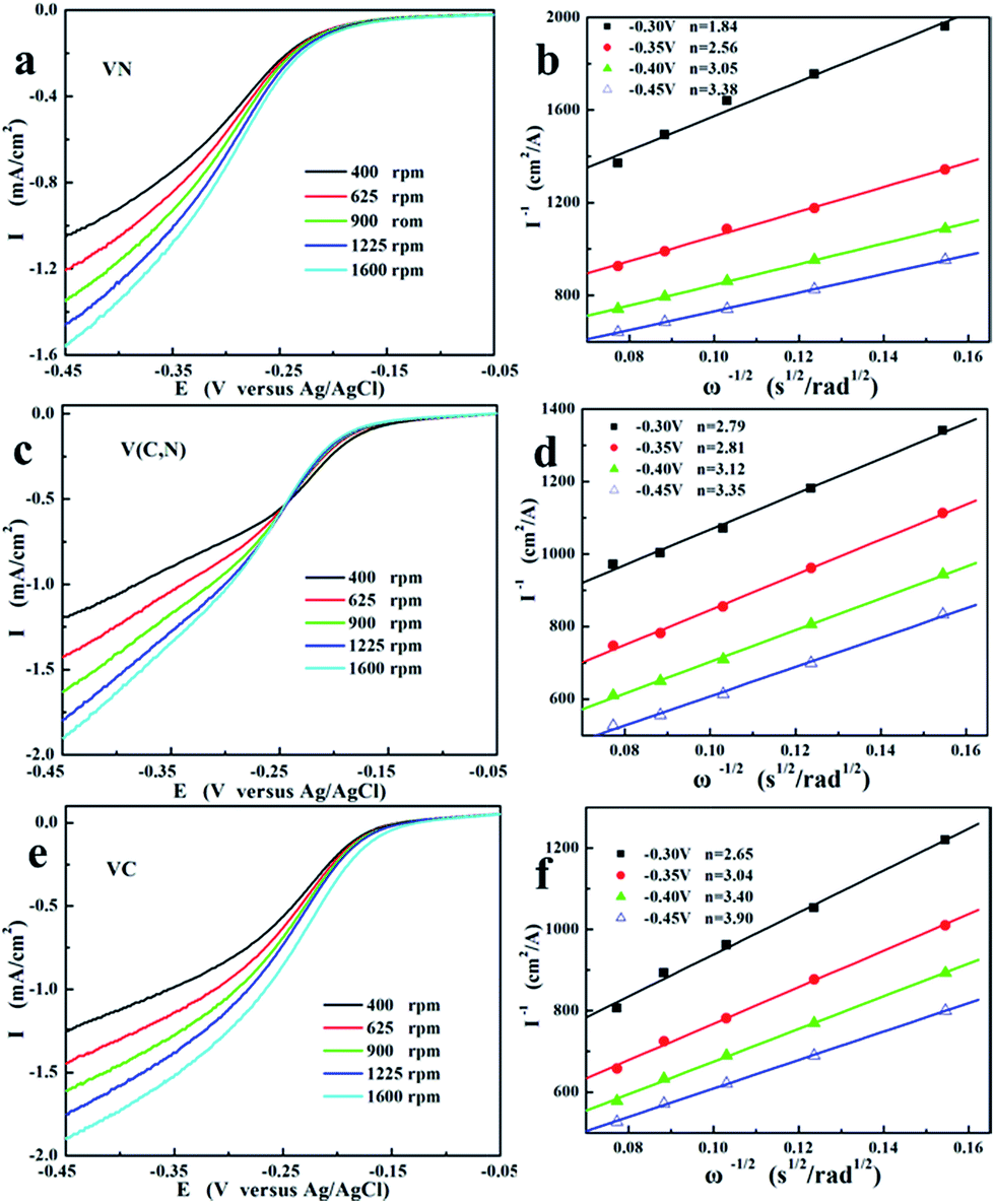 | ||
| Fig. 3 Rotating-disk voltamperograms of (a) VN, (c) V(C, N), and (e) VC in O2-saturated 1 M KOH at various rotation speeds (sweep rate is 0.005 V s−1). (b), (d), and (f) are the corresponding fitted Koutecky–Levich plots of VN, V(C, N), and VC, respectively, at −0.35 V, −0.40 V, −0.45 V, and −0.5 V vs. Ag/AgCl. | ||
The increased reaction electron numbers reveal the enhancement of the 4-electron reaction (reaction (3)) with the decreasing reaction potential. This is due to the deceased electron potential promotes the ORR on catalytic surface. Combining with RDE and Tafel results, the dependence of the kinetics parameters on the anion for ORR could be calculated. The plotted polarization curves, as shown in Fig. 2f, E (vs. Ag/AgCl) vs. lgi, are known as “Tafel plots” and are derived from the Tafel equations shown below:
 | (5) |
Based on Tafel plots, the Tafel slope, the charge transfer coefficient of the ORR, and the exchange current density are obtained and the results are shown in Table 1.
| Catalyst | E 0 (V at 10 mV s−1) | E f (V at 10 mV s−1) | i f (mA cm−2) | b (mV dec−1) | α | i 0 (mA cm−2) |
|---|---|---|---|---|---|---|
| VN | −0.14 | −0.24 | 1.35 | 69.13 | 0.59 | 8.84 × 10⁻⁴ |
| V(C, N) | −0.17 | −0.25 | 2.05 | 73.29 | 0.60 | 6.94 × 10⁻⁴ |
| VC | −0.23 | −0.32 | 1.16 | 69.22 | 0.63 | 1.84 × 10⁻⁴ |
| Pt/C | −0.04 | −0.14 | 1.94 | 81.5 | 0.55 | 6.31 × 10⁻⁸ |
Table 1 clearly illustrates that the charge transfer coefficient (α) of the reaction decreased and the exchange current density (i0) increased with the increasing nitrogen content in the catalysts despite that V(C, N) shows the highest peak current (if) in LSV tests. The i0 went up with the increase of nitrogen content, which should be originated from the high catalytic performance between vanadium and nitrogen, as supported by the CV tests in Fig. 2. Previous studies have proved that the ORR catalytic performance of carbon can be improved in alkaline media by doped nitrogen.23,31 The catalytic performance of iron-based catalysts are enhanced by the pyridinic nitrogen functionalities in the interstices of graphitic sheets within the micropores.32 The incorporation between FeN4 and aligned carbon nanotubes also activates ORR.33 Four nitrogen atoms of FeN4 provide electrocatalytic site towards ORR. The increased nitrogen content of the carbon support improves both the activity towards ORR and the selectivity towards the reduction of oxygen to OH− (4e− reaction).34
As the most effective catalyst, the specific surface area of VN is tested by Brunauer–Emmett–Teller (BET) test and the result is provided in ESI, Fig. S4b.† Results show that VN has a specific surface area of 30.6 m2 g−1. The stability test of VN is shown in ESI, Fig. S4c,† which reveals that the catalytic performance has little degradation after 1000 cycles. The slight decrease of initial oxidation potential may result from the oxidation of VN and the decrease of oxygen concentration in the electrolyte. It could be deduced that VN has a good long-term stability. Previous studies showed that Nafion was a proton exchanger and was mainly suitable for acidic media. When Nafion is used as a binder with the catalyst, there will be a three-phase interface formed between the catalyst, Nafion, and the electrolyte. Therefore, if the pH is different between the ‘free’ aqueous electrolyte and the Nafion polymer, there will be a potential drop at each of these interfaces.35 However, there is no study showing the magnitude of the potential drop and it is unclear if the use of Nafion will greatly impact the catalyst performance in an alkaline media. A recent study on alkaline fuel cells showed that Nafion could serve as a binder that uptakes water/electrolyte in the alkaline media.36 This study showed that the use of Nafion binder led to superior performance compared with the use of either non-conductive hydrophobic Polytetrafluoroethylene (PTFE) or anion-conductive hydrophobic Fumion. The better performance of Nafion in the alkaline media compared with other commonly used binders can be explained by the fact that Nafion is more hydrophilic due to its unique structure of sulfonic acid functional groups self-organizing into arrays of hydrophilic water channels through which small ions can be easily transported.37 Based on this study and many other published papers,4,8,38 we believe the use of Nafion in an alkaline media is not an issue. In addition, Nafion has been used as a standard binder for all catalysts in our experiments; therefore, the comparison of the catalyst performance is fair and reasonable. To study the influence from the counter electrode, graphite electrode was also used as the counter electrode and tested for VN in Ar- and O2-saturated electrolyte. The results (ESI, Fig. S5a–d†) clearly show that there is almost no difference in the onset potential and peak potential of the polarization curves with Pt and graphite as the counter electrode. And only slight differences in current density are found at different scan rates. The results suggest that Pt is stable in the electrolyte and the use of Pt as the counter electrode is acceptable. Although the absolute current in ORR will be different with different counter electrodes, the comparison of the ORR performance in the manuscript is fair and reasonable since we used Pt for all the tests.
In conclusion, this study reports the successful synthesis of VN by a simple hydrothermal method under mild conditions. VC and V(C, N) are synthesized by the reduction of graphene-supported V2O3 in hydrogen and ammonia atmospheres, respectively. Electrochemical tests reveal that the ORR catalytic performance of VN, V(C, N), and VC is enhanced by the increasing nitrogen content in the catalysts. VN, which shows an approaching ORR onset potential to Pt/C catalyst but with rather low cost and rich sources, is believed to be a promising alternative nonprecious metal-based catalyst for ORR. The hydrothermal synthesis methods of VN open a new access to synthesize metal nitrides, which make the structure tailoring and performance modulation more feasible than traditional carbon-thermal synthesis methods.
Acknowledgements
Financial support for this work was provided by the U.S. Department of Energy (DE-EE0003208), the Research Growth Initiative Program of the University of Wisconsin-Milwaukee (UWM), promotive research fund for young and middle-aged scientists of Shandong Province China (no. BS 2011CL005), and Science Development Project of Shandong Province China (no. J11LD02). The authors thank Professor M. Gajdardziska-Josifovska for TEM access at the UWM HRTEM Laboratory, Dr H. A. Owen for technical support with SEM analyses, Dr S. E. Hardcastle for technical support with XRD and XPS analyses, and Mr Jianyang Li for help with the structure diagram. The SEM imaging was conducted at the UWM Electron Microscope Laboratory. The XRD and XPS were conducted at the UWM Advanced Analysis Facility.References
- B. D. James, J. A. Kalinoski and K. N. Baum, Mass Production Cost Estimation for Direct H2 PEM Fuel Cell Systems for Automotive Applications: 2010 Update, The National Renewable Energy Laboratory (NREL) & The U.S. Department of Energy, 2010 Search PubMed.
- B. C. H. Steele and A. Heinzel, Nature, 2001, 414, 345–352 CrossRef CAS PubMed.
- Z. Chen, D. Higgins, A. Yu, L. Zhang and J. Zhang, Energy Environ. Sci., 2011, 4, 3167–3192 CAS.
- Y. Li, W. Zhou, H. Wang, L. Xie, Y. Liang, F. Wei, J.-C. Idrobo, S. J. Pennycook and H. Dai, Nat. Nanotechnol., 2012, 7, 394–400 CrossRef CAS PubMed.
- V. R. Stamenkovic, B. Fowler, B. S. Mun, G. Wang, P. N. Ross, C. A. Lucas and N. M. Markovic, Science, 2007, 315, 493–497 CrossRef CAS PubMed.
- I. E. L. Stephens, A. S. Bondarenko, U. Gronbjerg, J. Rossmeisl and I. Chorkendorff, Energy Environ. Sci., 2012, 5, 6744–6762 CAS.
- D. Wang, Y. Yu, H. L. Xin, R. Hovden, P. Ercius, J. A. Mundy, H. Chen, J. H. Richard, D. A. Muller, F. J. DiSalvo and H. D. Abruña, Nano Lett., 2012, 12, 5230–5238 CrossRef CAS PubMed.
- Y. Liang, Y. Li, H. Wang, J. Zhou, J. Wang, T. Regier and H. Dai, Nat. Mater., 2011, 10, 780–786 CrossRef CAS PubMed.
- K. Kordesch, V. Hacker, J. Gsellmann, M. Cifrain, G. Faleschini, P. Enzinger, R. Fankhauser, M. Ortner, M. Muhr and R. R. Aronson, J. Power Sources, 2000, 86, 162–165 CrossRef CAS.
- Z. Wen, S. Cui, H. Pu, S. Mao, K. Yu, X. Feng and J. Chen, Adv. Mater., 2011, 23, 5445–5450 CrossRef CAS PubMed.
- A. L. Bouwkamp-Wijnoltz, W. Visscher, J. A. R. van Veen and S. C. Tang, Electrochim. Acta, 1999, 45, 379–386 CrossRef CAS.
- H.-J. Zhang, X. Yuan, L. Sun, X. Zeng, Q.-Z. Jiang, Z. Shao and Z.-F. Ma, Int. J. Hydrogen Energy, 2010, 35, 2900–2903 CrossRef CAS PubMed.
- H. Meng and P. K. Shen, Electrochem. Commun., 2006, 8, 588–594 CrossRef CAS PubMed.
- H. Chhina, S. Campbell and O. Kesler, J. Power Sources, 2008, 179, 50–59 CrossRef CAS PubMed.
- Z. Yan, M. Cai and P. K. Shen, J. Mater. Chem., 2011, 21, 19166–19170 RSC.
- X. Ma, H. Meng, M. Cai and P. K. Shen, J. Am. Chem. Soc., 2012, 134, 1954–1957 CrossRef CAS PubMed.
- Z. Wen, S. Ci, F. Zhang, X. Feng, S. Cui, S. Mao, S. Luo, Z. He and J. Chen, Adv. Mater., 2012, 24, 1399–1404 CrossRef CAS PubMed.
- G. Wu, K. L. More, C. M. Johnston and P. Zelenay, Science, 2011, 332, 443–447 CrossRef CAS PubMed.
- E. F. de Souza, C. A. Chagas, T. C. Ramalho and R. B. de Alencastro, Dalton Trans., 2012, 41, 14381–14390 RSC.
- T. Huang, S. Mao, H. Pu, Z. Wen, X. Huang, S. Ci and J. Chen, J. Mater. Chem. A, 2013, 1, 13404–13410 CAS.
- A. Ortega, M. A. Roldan and C. Real, Int. J. Chem. Kinet., 2006, 38, 369–375 CrossRef CAS.
- Z. Zhao, Y. Liu, H. Cao, S. Gao and M. Tu, Int. J. Refract. Met. Hard Mater., 2008, 26, 429–432 CrossRef CAS PubMed.
- J. Zhang, K. Sasaki, E. Sutter and R. R. Adzic, Science, 2007, 315, 220–222 CrossRef CAS PubMed.
- G. He, Z. Yan, X. Ma, H. Meng, P. K. Shen and C. Wang, Nanoscale, 2011, 3, 3578–3582 RSC.
- P. Duwez and F. Odell, J. Electrochem. Soc., 1950, 97, 299–304 CrossRef CAS PubMed.
- J.-S. Lee, G. S. Park, S. T. Kim, M. Liu and J. Cho, Angew. Chem., 2013, 125, 1060–1064 CrossRef.
- T. S. Olson, S. Pylypenko, J. E. Fulghum and P. Atanassov, J. Electrochem. Soc., 2010, 157, B54–B63 CrossRef CAS PubMed.
- K. Gong, F. Du, Z. Xia, M. Durstock and L. Dai, Science, 2009, 323, 760–764 CrossRef CAS PubMed.
- L. Zhang, J. Zhang, D. P. Wilkinson and H. Wang, J. Power Sources, 2006, 156, 171–182 CrossRef CAS PubMed.
- T. Sharifi, G. Hu, X. Jia and T. Wågberg, ACS Nano, 2012, 6, 8904–8912 CrossRef CAS PubMed.
- S. Shanmugam and T. Osaka, Chem. Commun., 2011, 47, 4463–4465 RSC.
- M. Lefèvre, E. Proietti, F. Jaouen and J.-P. Dodelet, Science, 2009, 324, 71–74 CrossRef PubMed.
- J. Yang, D.-J. Liu, N. N. Kariuki and L. X. Chen, Chem. Commun., 2008, 329–331 RSC.
- C. Médard, M. Lefèvre, J. P. Dodelet, F. Jaouen and G. Lindbergh, Electrochim. Acta, 2006, 51, 3202–3213 CrossRef PubMed.
- R. Subbaraman, D. Strmcnik, V. Stamenkovic and N. M. Markovic, J. Phys. Chem. C, 2010, 114, 8414–8422 CAS.
- M. S. Naughton, G. H. Gu, A. A. Moradia and P. J. A. Kenis, J. Power Sources, 2013, 242, 581–588 CrossRef CAS PubMed.
- K. Schmidt-Rohr and Q. Chen, Nat. Mater., 2008, 7, 75–83 CrossRef CAS PubMed.
- S. Chen, J. Bi, Y. Zhao, L. Yang, C. Zhang, Y. Ma, Q. Wu, X. Wang and Z. Hu, Adv. Mater., 2012, 24, 5593–5597 CrossRef CAS PubMed.
Footnotes |
| † Electronic supplementary information (ESI) available: Experimental methods; SEM characterization of the catalysts; Tafel test of Pt/C catalyst; BET and cyclic performance tests of VN. See DOI: 10.1039/c4nr02646b |
| ‡ These authors contributed equally to this work. |
| This journal is © The Royal Society of Chemistry 2014 |