DOI:
10.1039/C4NR00754A
(Paper)
Nanoscale, 2014,
6, 7594-7603
Graphene levitons and anti-levitons in magnetic fields†
Received
11th February 2014
, Accepted 9th May 2014
First published on 13th May 2014
Abstract
The leviton is an electron or hole wavepacket that rides the surface of the Fermi sea. When a series of Lorentzian or Gaussian time dependent pulses are applied to an ultracold system a soliton-like excitation with only one electron and no localised hole emerges. Graphene is a unique system where the Fermi surface may arise from a Dirac point and therewith the levitons character may display many interesting features. For example, the leviton formation may be associated with a chiral anomaly, and inside a single potential step an anti-leviton forms. We show that the application of weak magnetic fields may switch on and off the leviton Klein tunnelling. Also, in a moderate field negative refraction arises along a curved trajectory, whereas with a stronger field a new elementary excitation – the levity vortex – in the reflected wavefunction occurs. Herein we describe these phenomena in detail along with a complete explanation of the transmission of graphene levitons at a step potential in terms of the probability densities and a series of phase diagrams and the tunnelling times.
1 Introduction
In the 19th Century John Scott Russell was the first to take note of the propagation of a single, localised wave that had consistency of shape and velocity as it moved through a channel of water. The wave, nowadays known as a near-soliton, was generated when a boat suddenly stopped in the Union Canal that runs from Falkirk to Edinburgh, in Scotland. Pure solitons are invariant in shape and speed when they collide with other solitons, but Scott Russell's “wave of translation” was diminished in amplitude (dissipated) as it continued on its journey along the waterway. Having observed this phenomenon, Scott Russell had discovered a method to propel boats in front or atop of these waves and an impetus to design hull shapes that had minimal resistance began. The research that followed led to the Scottish system of “fly-boats” which were drawn by horses along the banks of canals at relatively large speeds with lowered resistance. The lowering of the resistance occurred once the boat, which started at low velocity behind a wave, was suddenly jerked forward so that it rose atop the wave.1 Scott Russell then focused upon optimising the shape of the hull and stern of the boats for canal transit. The work pre-empted an era of increasingly fast naval vessels. Just like the fly-boats, a single electron wave-packet can travel unimpeded on the top of the Fermi sea. This wave packet is a kind of soliton that has recently been found experimentally by Dubois et al.2 This modern day observation is of a new quasiparticle that has been named the “leviton” because its existence was predicted by Levitov and co-workers.3–5 The sea of electrons have their highest energies close to the Fermi surface. Under usual conditions a perturbation to the electron leaves behind a positive quasiparticle called a “hole”. At low temperatures, a Lorentzian or Gaussian pulse can inhibit the formation of particle-hole excitations and generate an electron wave that rises out of the Fermi sea, in analogy to Scott Russell's wave of translation.
In our work we apply Gaussian shaped pulses to produce levitons through graphene. Graphene is the first two-dimensional (2D) crystal observed6 and it is an allotrope of carbon similar to diamond, fullerene and charcoal – all of which have their own unique properties.7 It may usually be found in the form of highly ordered pyrolytic graphite (HOPG), whereby individual 2D graphene layers stack on top of one another to form a crystalline lattice.8 Its stability is due to a tightly packed, periodic array of carbon atoms and an sp2 orbital hybridisation – a combination of orbitals px and py that constitute the σ-bond.9 The final third are pz electrons of the carbon atom that make up the π-bond, and it is key to the half-filled band and the Dirac electronic spectrum.9 The stability of the 2D crystals such as graphene, silicene and germanene may be associated with small displacements of the sub-lattices A and B which can be slightly shifted in the z-direction.10 Graphene has not only a monolayer hexagonal structure but it is more conductive than copper, with mobilities reaching up to 200![[thin space (1/6-em)]](https://www.rsc.org/images/entities/char_2009.gif) 000 cm2 V−1 s−1.11–13 Charge carriers in graphene travel with a Fermi velocity vF ≈ 106 m s−1,10,11,14 which is approximately 1/300 the speed of light. It has a minimum conductivity σ0 ≈ 4e2/h,15 which is approximately double that for the conductance quantum.16,17 The levitons represent electronic coherent wavepackets. As we will show, the levitons in graphene are very sensitive to external magnetic fields and can be propagated over relatively large distances (as compared to, for example, plasmons in noble metals18). Over the last few years subwavelength devices have been engineered to produce negative refraction.19 However, it has been shown that graphene can naturally bend light in the opposite direction to what is intuitive and super resolution imaging devices have been predicated.20 The leviton, travelling atop the Fermi sea, is a type of long-lived quasiparticle that opens up a new kind of quantum electronics, one that may ultimately result in devices where the leviton could act to communicate quantum information and to control nanoscale circuitry.
000 cm2 V−1 s−1.11–13 Charge carriers in graphene travel with a Fermi velocity vF ≈ 106 m s−1,10,11,14 which is approximately 1/300 the speed of light. It has a minimum conductivity σ0 ≈ 4e2/h,15 which is approximately double that for the conductance quantum.16,17 The levitons represent electronic coherent wavepackets. As we will show, the levitons in graphene are very sensitive to external magnetic fields and can be propagated over relatively large distances (as compared to, for example, plasmons in noble metals18). Over the last few years subwavelength devices have been engineered to produce negative refraction.19 However, it has been shown that graphene can naturally bend light in the opposite direction to what is intuitive and super resolution imaging devices have been predicated.20 The leviton, travelling atop the Fermi sea, is a type of long-lived quasiparticle that opens up a new kind of quantum electronics, one that may ultimately result in devices where the leviton could act to communicate quantum information and to control nanoscale circuitry.
2 Levitons in a magnetic field
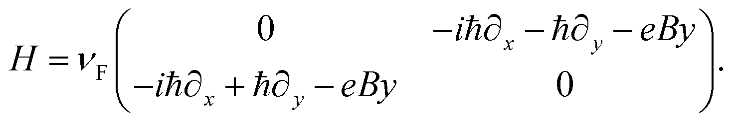
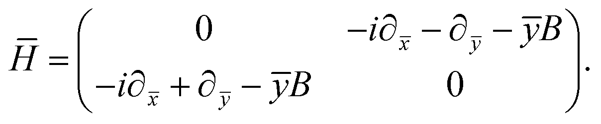
The stimulus for the creation of the levitons may be light from a laser, injection through a ferromagnetic layer or voltage pulses through an electrode.2 Once a leviton is produced it can be channelled through a waveguide or constriction, as in ref. 2. For example, the pulses carry integer charge q = ne and excite n electrons above the Fermi level, with the compensation for excited electron dislocation occurring with the electronic sea moving so as to prevent the creation of holes and to fill-in the void that is left.5 In this way there is a uniform electron sea. This creates a system of right and left moving electrons as the leviton moves along the Fermi surface. The fact that the Fermi sea remains intact is due to there being no entanglement between the quasiparticles, because of there being no holes. In graphene the propagation of excited charge carriers is extremely fast and closely linked to the Dirac spectrum.21 As such, we solve the system of equations,11| |  | (1) |
where,| |  | (2) |
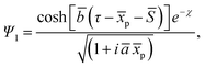
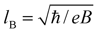
The wavefunction Ψ1 represents the motion of an electron as a second electron wave Ψ2 maneuvers to fill any void created by the former and to produce a complete Fermi sea. The leviton moves with Fermi velocity, vF, through the graphene. In the above we have introduced the Landau gauge in the form A = (−By, 0, 0). With the magnetic flux density B, a magnetic length  is incorporated into eqn (1) and (2).This magnetic scale is equivalent to
  where B becomes a dimensionless parameter. We now write the dimensionless form of eqn (1),
| |  | (3) |
and
| |  | (4) |
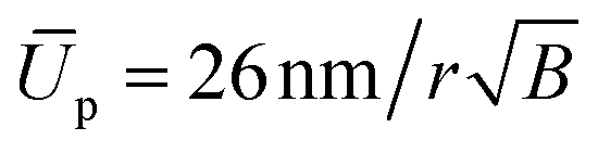
Using the magnetic length scale, time is written in dimensionless units as, τ = vFt/26 nm, and the positions are defined as ![[x with combining macron]](https://www.rsc.org/images/entities/i_char_0078_0304.gif) = x/26 nm and ȳ = y/26 nm. The height of a potential step is defined as Up = νFħ/r, where r is an effective step dimension. In dimensionless units
= x/26 nm and ȳ = y/26 nm. The height of a potential step is defined as Up = νFħ/r, where r is an effective step dimension. In dimensionless units 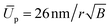 . Throughout we will apply a Gaussian wavepacket to the system. In general a leviton could consist of many particles and conceivably have different shapes that could be self-consistently determined. In the present work we are interested in relativistic levitons in graphene, which may have similarities with point-like relativistic particles. For this purpose we have to construct a wavepacket that allows correspondence to a single quantum number. By way of reasonable approximation we consider a very narrow distribution of quantum numbers around the chosen one. It is believed that the best way to do this is for it to be described by a Gaussian distribution which corresponds (after a Fourier transform) to the Gaussian wave packet that is studied in this paper. Moreover, due to the same reason (the narrow range of quantum numbers) the Gaussian packet may in general be more stable than any other shapes of the wavepackets. Indeed, Mita showed that any non-Gaussian wavepacket takes a Gaussian shape as it disperses with time.22 Furthermore, in magnetic fields the electron wave function associated with a Landau level has a dominant Gaussian shape. That is why for levitons in magnetic fields the most natural choice is the Gaussian shape for the wavepacket under study. Of course the Lorentzian shape of the wavepacket is equally applicable to study levitons. However in this case, for the Lorentzian wavepacket, the distribution of the quantum numbers is significantly more broadly dispersed. Therefore, packets of non-Gaussian waveforms can create more noise at their detection (see, ref. 2). In addition, that may hide some other leviton features and transport characteristics. These arguments stimulated us to choose the Gaussian wavepackets as the most appropriate to study levitons in graphene. Here the leviton is formed with the height and width of a Gaussian wavepacket with initial given shape,
| |  | (5) |
and
| | | Ψ2 = (1 + āȳp/(1 + iāp))Ψ1, | (6) |
where,
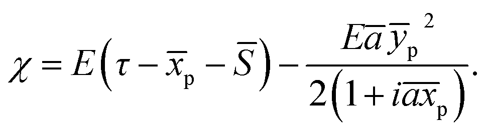
| |  | (7) |
In the above a bar above a parameter means that it has been made dimensionless by dividing by  . The energy associated with the leviton wavepacket is E = αŪp, where α denotes the ratio of the electron energy to that of the potential. The shape of the soliton is defined by ā and
 ![[b with combining macron]](https://www.rsc.org/images/entities/i_char_0062_0304.gif) , which give the dimensions of the particle. In Fig. 1(a), the leviton is defined with parameters ā = 0.25 and = 2. The parameters defining the coordinates of the Gaussian beam are given by S = 2Lcosθ, where L characterises the initial position of the beam; p = cosθ + ȳsinθ; and ȳp = −sinθ + ȳcosθ. Here θ is the angle that the leviton would approach the step in the absence of an applied magnetic field. In the examples that we present, the leviton is envisaged to be formed by injecting charge pulses2 into graphene that lies on a substrate that enables transport with high Fermi velocity, e.g. quartz, that has νquartzF = (2.49 ± 0.30) × 106 m s−1,23 at low temperature. Part way along the quartz substrate would be a strip of material that results in a lowering of the Fermi velocity. This material could be SiC which has a νSiCF ≈ 0.5νquartzF. In analogy with the soliton observed by Russell, where a boat suddenly lurched to produce the phenomenon, the sudden change in velocity of the wavepacket of the electron results in the propagation of a Gaussian or Lorentzian pulse. The leviton is shown schematically in Fig. 1(b). The band structure topology of graphene is unusual because it consists of two surfaces that come together at the so-called Dirac energy ED, a charge neutrality point.24 Unperturbed, ED will coincide with the Fermi level EF, but upon excitation these energies separate and a massive increase in carrier density ensues.25 The valence and conduction bands of graphene are symmetrical in the unperturbed state, with a conical shape around the Brillouin Zone (BZ) edges. They touch at the Dirac points. Around the zero band-gap at the Dirac points, the electrons and holes have a linear dispersion relation, which gives rise to many peculiar and unusual material properties. In this region, where ED = 0, the dispersion relation is |E − ED| = ħνF|k − K| (where K is a corner of the BZ) from which the group velocity of excitations is vF ≈ 106 m s−1. This is a lower effective speed of light because the charge carriers have an effective mass of zero, giving rise to relativistic behaviour. It is important to note that in the opposite corner of the BZ another Dirac point exists that is denoted as K′. In graphene there are two sublattices which are denoted A and B. Each charge carrier is localised in one of these sublattices with the possibility of travelling from one to the next. This creates a pseudospin, which can be thought of as the up and down states of a spin-doublet, and so the charge carriers in graphene behave like massless spin-1/2 particles. Originally Wallace,9 has considered a simple tight-binding model with a single hopping integral of an electron from one carbon atom to its first and second nearest neighbours only. Wallace's conclusions were stark; an electrical conductivity should theoretically exist for 2D graphene. To elaborate; at six positions of the BZ, Dirac points (K and K′) exist. These are points in momentum space for which the energy E(p0) = 0, where p0 = ħK (or ħK′). Here, we have denoted the momentum as a vector p = (px,py) = ħk, where k = (kx,ky) is the wave vector.6 The energy eigenvalues were found to take a gapless form,9
, which give the dimensions of the particle. In Fig. 1(a), the leviton is defined with parameters ā = 0.25 and = 2. The parameters defining the coordinates of the Gaussian beam are given by S = 2Lcosθ, where L characterises the initial position of the beam; p = cosθ + ȳsinθ; and ȳp = −sinθ + ȳcosθ. Here θ is the angle that the leviton would approach the step in the absence of an applied magnetic field. In the examples that we present, the leviton is envisaged to be formed by injecting charge pulses2 into graphene that lies on a substrate that enables transport with high Fermi velocity, e.g. quartz, that has νquartzF = (2.49 ± 0.30) × 106 m s−1,23 at low temperature. Part way along the quartz substrate would be a strip of material that results in a lowering of the Fermi velocity. This material could be SiC which has a νSiCF ≈ 0.5νquartzF. In analogy with the soliton observed by Russell, where a boat suddenly lurched to produce the phenomenon, the sudden change in velocity of the wavepacket of the electron results in the propagation of a Gaussian or Lorentzian pulse. The leviton is shown schematically in Fig. 1(b). The band structure topology of graphene is unusual because it consists of two surfaces that come together at the so-called Dirac energy ED, a charge neutrality point.24 Unperturbed, ED will coincide with the Fermi level EF, but upon excitation these energies separate and a massive increase in carrier density ensues.25 The valence and conduction bands of graphene are symmetrical in the unperturbed state, with a conical shape around the Brillouin Zone (BZ) edges. They touch at the Dirac points. Around the zero band-gap at the Dirac points, the electrons and holes have a linear dispersion relation, which gives rise to many peculiar and unusual material properties. In this region, where ED = 0, the dispersion relation is |E − ED| = ħνF|k − K| (where K is a corner of the BZ) from which the group velocity of excitations is vF ≈ 106 m s−1. This is a lower effective speed of light because the charge carriers have an effective mass of zero, giving rise to relativistic behaviour. It is important to note that in the opposite corner of the BZ another Dirac point exists that is denoted as K′. In graphene there are two sublattices which are denoted A and B. Each charge carrier is localised in one of these sublattices with the possibility of travelling from one to the next. This creates a pseudospin, which can be thought of as the up and down states of a spin-doublet, and so the charge carriers in graphene behave like massless spin-1/2 particles. Originally Wallace,9 has considered a simple tight-binding model with a single hopping integral of an electron from one carbon atom to its first and second nearest neighbours only. Wallace's conclusions were stark; an electrical conductivity should theoretically exist for 2D graphene. To elaborate; at six positions of the BZ, Dirac points (K and K′) exist. These are points in momentum space for which the energy E(p0) = 0, where p0 = ħK (or ħK′). Here, we have denoted the momentum as a vector p = (px,py) = ħk, where k = (kx,ky) is the wave vector.6 The energy eigenvalues were found to take a gapless form,9
| |  | (8) |
where the plus and minus signs refer to the upper and lower half-filled bands respectively and
a is related to the separation between carbon atoms (
a ≈ 0.246 nm).
11,16 By expanding the above equation in the vicinity of the
K or
K′ points, we obtain the linear dispersion relation that is given by
E± =
νFħ|
δk|, where
k =
K +
δk. These are known as Dirac cones. Here, in the Dirac points a direct contact of the conduction and valence bands occurs,
6,9,13,16 thus pertaining to a zero energy band-gap.
6,9,16 However, a propagating leviton does not create a localised electron–hole pair as there is no local hole production. Therefore, the charge carrier dynamics in effect exist between the electronic wavefunctions of the Dirac equations of the sublattices of
A and
B.
 |
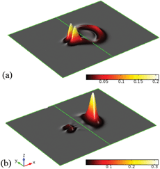
| | Fig. 1 The leviton is formed at time = 0 as a Gaussian shaped pulse. In our numerical experiments, a potential step of size Up is located to the right of the central line (green online). This can be seen in (a). The colour bar denotes the value of the probability density of the leviton |Ψ1|2. In (b) a schematic of the formation of the leviton at a quantum point contact is given. | |
Graphene displays several anomalous quantum phenomena, even at room temperature.11,26 The Quantum Hall Effect (QHE) has been observed for both single and bilayer graphene,27,28 in the presence of a magnetic field B. The application of the magnetic field brings about the emergence of Landau levels in the graphene system, taking a discrete form that occurs above and below ED. The energies associated with these discrete energy levels are given by,26
| | 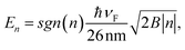 | (9) |
where
n = 0, ±1, ±2, … is the index of a level (
i.e. the Landau quantum number). The associated Hall conductivity is
σH =
ge(
n + 1/2)/2π
lB2, where
e is the electric charge and
g is the degeneracy.
16,17 For graphene, a fourfold degeneracy exists – two spins, and the valley degeneracy of the
K and
K′ Dirac points.
6–9 Additionally, the fractional QHE has been observed for both monolayer and bilayer graphenes (
cf. for details
6−9,27,28). The separation between Landau levels is largest between
n = 0 and 1. When
n is large the higher energy levels are in close proximity. The Landau energies for applied field strengths of
B = 5 mT and
B = 2.5 T are shown in
Fig. 2(a) and (b), respectively. Landau quantisation has been experimentally found to occur in fields below
B = 5 mT.
29 Another quantum phenomenon observed is the Klein Tunnelling. In this situation an electron can go through a barrier of any height.
26–28,30 The effect is related to the nature of the gapless Dirac spectrum, whereby an electron can be transformed into a hole or
vice versa under an influence of any potential. So far, a perfect transmission is demonstrated for square potentials only, and is dependent upon the angle of incidence
θ relative to the barrier
31,32. Confined bound states will arise for energies close to the Dirac point.
31,32 Further details regarding how this confinement effect may relate to the special waveguide geometry has been discussed in
ref. 33–37.
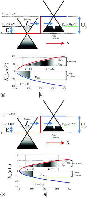 |
| | Fig. 2 Once a leviton is formed it can propagate through the graphene structure and devices can be designed with different shaped potential barriers. Here we investigate the potential step. In (a) and (b) the leviton takes form at the left of the step and tunnels with energy, E, lower than the electrostatic potential, Up. Inside the step an anti-leviton forms. The leviton–anti-leviton propagates through the system with Fermi velocity, νF ≈ 106 m s−1. The leviton is a single electron wavepacket that surfs the Fermi sea as a soliton. An anti-leviton forms in the valence band after the leviton meets with the elevated potential of the step. In (a) an applied magnetic field is B = 5 mT and in (b) B = 2.5 T. The bottom plots in (a) and (b) show Landau energies En for these values of magnetic field. The energy levels for each quantum number n are joined as a guide for the eye. The positive (coloured red online) energies are prior to engagement of the leviton with the step, whereas the negative ones are within the step (blue online). The Landau levels are measured from ED to the left and right of the step boundary. | |
3 Leviton and anti-leviton dynamics into and within a potential step
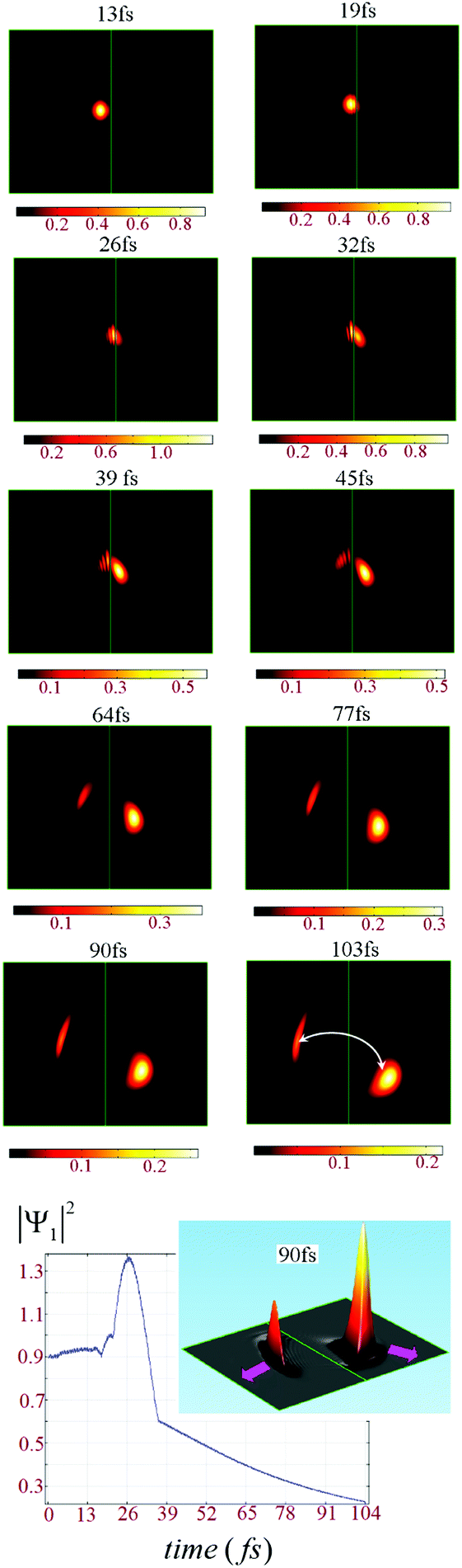
The leviton is formed to the left of a potential step, as is shown in Fig. 1(a) and 2. Transport through the potential step is strongly dependent upon the angle of incidence. The presence of a magnetic field bends the leviton trajectory into the step. We demonstrate some of the unusual phenomena that occur when varying field strengths are applied to the system. In Fig. 3, a small magnetic field of B = 5 mT has been applied. A potential step of size Up = 91 meV is created and the leviton has initial energy E = 0.4Up (corresponding to n = 322, see Fig. 2). The leviton travels from left to right. At 13 fs it is about to touch the boundary of the step. In Fig. 3 the contact with and transition into the step is marked by two peaks in the probability density. At 26 fs the leviton exists either side of the boundary, rippling in its transition, but maintaining almost full transmission. A very small backscattering of the wavefunction occurs, which can be visually seen in the inset of Fig. 3 (two darker areas on the left of the step). In this inset the height of the probability density after 103 fs is shown, with the transmitted form of the wavefunction to the right. On the left one can see two “splinters” of the wavefunction, that have propagated backwards since the collision with the step. This is a very small and almost insignificant reflection, except when one begins to examine what occurs to the system if the magnetic field is increased (or as α → 1).
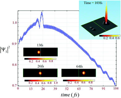 |
| | Fig. 3 The magnetic field has been introduced using the Landau gauge, A = (−By, 0, 0) where B = 5 mT. In such a small field any deviation of the trajectory of the leviton is almost indiscernible. However, one can see that there emerges a very small backscattering of the wavefunction (see the top inset). Underneath the plot of maximum probability density |Ψ1|2 is the time evolution of the leviton into the potential step at time increments of 13–64 fs. The colour bars indicate the size of |Ψ1|2. The ratio of leviton energy to step height is α = 0.4. | |
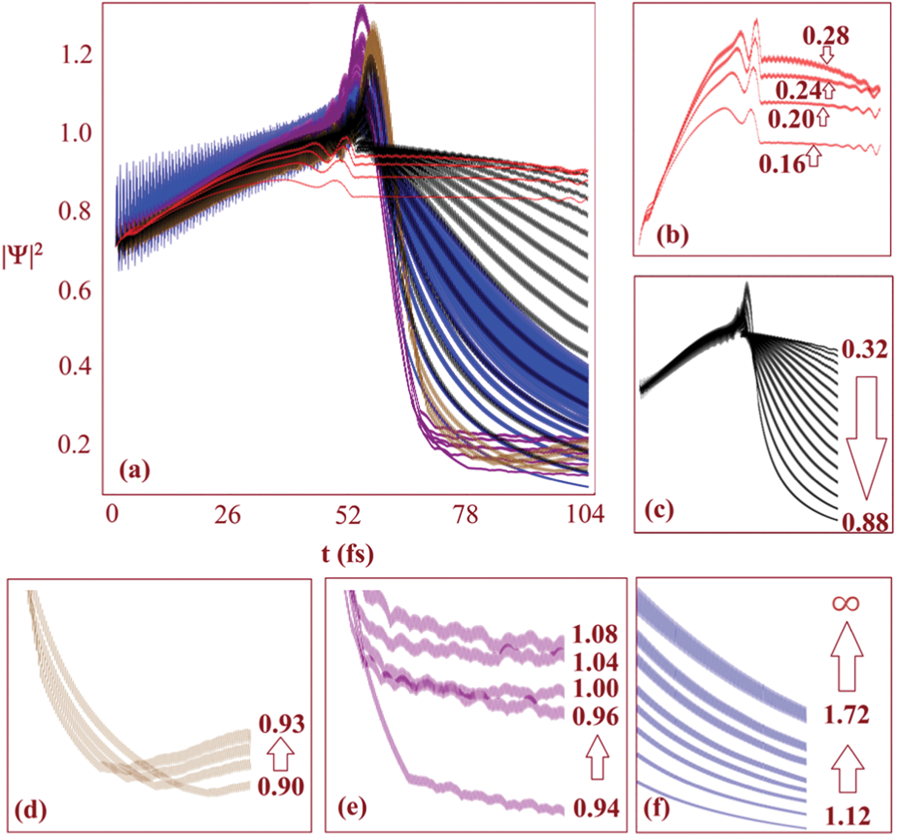
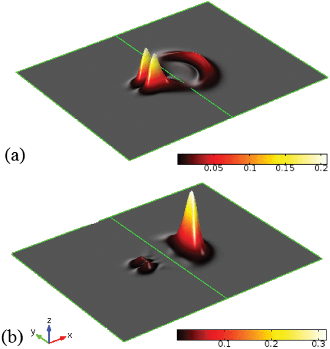
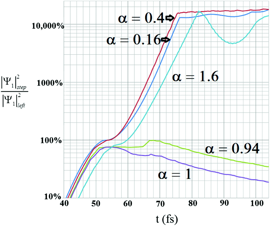
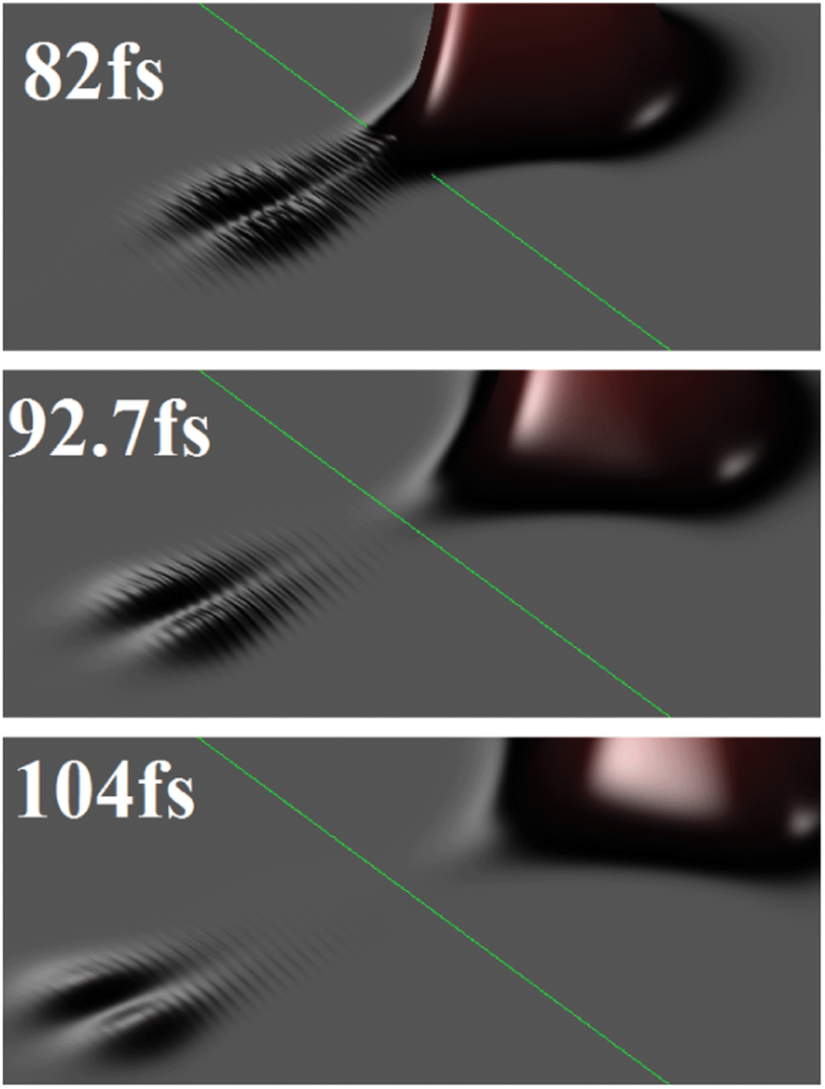
A magnetic field of B = 2.5 T is introduced to the system that has a potential step of Up = 2 eV, thus giving a magnetic length parameter of lB ≈ 16 nm. The trajectory of the wavepacket through the graphene layer (that lies on a quartz substrate with νF ≈ 2 × 10⁶ m s−1 (ref. 23)) can be seen in Fig. 4. Various geometries of graphene islands and fabrication techniques have been described in detail in ref. 38. Fig. 4 shows the time evolution of the probability density over 104 fs. At the potential step the curvature of the trajectory of the wavepacket becomes far more obvious than in the case of B = 5 mT. The upturn in the wavepackets trajectory as it approaches the step boundary leads to a remarkable effect. At 26 fs one can see in Fig. 4 that the probability density increases as the leviton compresses its form against the step, |Ψ1|2 > 1. Part of the wavefunction slides up the step, before beginning to split into a reflected “ray”, in analogy to an optical beam. The transmitted ray moves downwards at an angle into the step, exhibiting clear negative refraction (previous studies have demonstrated graphene as a Veselago lens, e.g.ref. 19). The beginning of this can be seen at 32 fs. Due to the magnetic field the trajectory curves, as is indicated in Fig. 4 at 103 fs. Thus, we can control the negative refraction using the strength of the magnetic field. Using larger magnetic fields increases the curvature of the trajectory too. Eventually, with larger magnetic fields, the maximum probability density is always higher on the left hand side of the step after collision and another remarkable occurrence is seen. For example, at B = 6.5 T the majority of the probability density of the reflected ray far exceeds that of the transmitted one. The transmitted ray slides down the internal wall of the step. However, the reflected ray begins to swirl. This is shown in Fig. 5, where the emergence of a vortex state can be seen. The reflected wavepacket forms a closed trajectory that moves backwards, spiralling anti-clockwise in close proximity to the step boundary (in the ESI,† animations of the graphene system discussed can be found). We call this new excitation the levity vortex. In addition to the translational and rotational motion of the wavepacket, very fast periodic oscillations occur. This trembling motion occurs even with the application of very small magnetic fields. The maximum probability density fluctuates as the electron propagates along its trajectory. In Fig. 6(a) the maximum probability density either side of the step boundary is shown as the leviton propagates into it as a function of time (for a step of 91 meV and magnetic field of B = 5 mT). Each curve is representative of a different value of α. These values of α strongly affect the durability of the excitation, with the greatest propensity for almost unhindered propagation happening deep below the height of the potential step, α < 0.28 (Fig. 6(a) and (b)). Beyond α = 0.28, to the right of the step boundary, the maximum probability density rapidly decreases as α approaches 1, i.e. when the leviton energy matches the height of the potential. One can see in Fig. 7(a) that when α = 1 the reflected wavefunction forms as the characteristic two “rays” moving back from the step (see the inset of Fig. 3 for a comparison). The maximum probability density is far higher than that of the transmitted ray. In Fig. 7(b), α = 0.9 is shown and the opposite is true – the transmitted beam contains a higher probability density. In the range α = 0.9 to 0.93 there begins to emerge plateaus in the maximum probability density after about 65 fs (shown in Fig. 6 (a) and (d)). These small maximum probability densities belong to the reflected pulse until the energy of the leviton exceeds the height of the potential. This can be seen in Fig. 8 where the maximum probability density to the left of the step (shown by light coloured lines – pink online) and in the step (darker lines, red online) are shown as a function of time. In Fig. 8(a), at α = 0.16, there is almost complete transmission through the boundary into the step. This is also true for the case shown in Fig. 8(b), at α = 0.4. When the potential of the step approaches α = 1 there is a far larger reflected component of the wavefunction and this can be seen in Fig. 8(c) for α = 1.0. When E exceeds the potential the transmission takes place without much impedance, as is demonstrated by the plot in Fig. 8(d). In Fig. 9, for the cases of α = 0.16, 0.40, 0.94, 1.00, and 1.6 the percentage of probability density of the wavefunction in the step with respect to outside it is given as the system evolves in time. When α = 0.16, this percentage of wavefunction probability density either side of the potential boundary is 100% for a duration of 1 fs from t = 52.6 fs. At this moment in time, the wavepacket is equally poised between the two sides of the step (see Fig. 8(c) and 9). From this time onwards there is only a small backscattering and most of the quasiparticle is transmitted. This is demonstrated in Fig. 9. This transitory period when the wavefunction is split equally over the interface is more fleeting when α = 0.4, and occurs from 53.6 fs to 54 fs. Once again nearly perfect transmission ensues, as can be seen in Fig. 9. When E = Up there is a high degree of reflection from the step and the maximum probability densities either side of the boundary never become exactly equal. Even when the maximum probability densities are close to equality on either side, this is not similar to the cases of α = 0.16 and 0.4 when the maximum probability densities are the same. In these cases the reflected pulse always has higher maximum probability density (see Fig. 8(c)). In Fig. 9 one can see that there is a large dip in the |Ψ1|step2/|Ψ1|left2 ratio when α = 1.6. This is due to a longer waiting time for the Gaussian wavepacket to cross the step interface. The peak has already passed but the tail is still in transition and rupturing into two backscattering wavepackets. The event whereby the wavefunction splits into these smaller reflective pulses, leaving the larger pulse and moving off the step boundary, occurs at 82 fs. At 92.7 fs, the coupling between the transmitted and reflected pulse reaches a critical level and their hold on one another is mostly relinquished, with the tails leaving the interface. When E is very close to the potential Up, the tails of the reflected and transmitted pulses remain connected for a large duration. We can see this even at 91 fs in Fig. 7(a) for α = 1. Indeed this remains true for ≈250 fs. In a confined geometry where the wavefunction will impinge upon the edges of the sample, this connection remains until dissipation due to the edges occurs (akin to the transmission of the soliton down the Union canal in Scott Russell's time when the canal boundary acted as a dissipative waveguide). There is a striking juxtaposition of reflected and transmitted elements of the wavefunction that diminishes as one reduces the α. Indeed, instead of appearing like a transmitted ripple (like when one drops a stone into a pond) for α ≈ 1, for smaller α the propagation into the step resembles more the continuous soliton. Fig. 9 also exhibits a smaller dip for tunnelling into the potential step for α = 0.16 for the duration of 84–92 fs whilst the transmitted and reflected pulses sever. We define the tunnelling time into the step by the time scale of first contact of the leviton with the step to when separation of the reflected and transmitted wavefunctions is complete or at least indiscernible. The transmission into the step is thus usually followed by some degree of back-scattering. For α = 1.6 this is clearly seen through the snap-shots in time of the leviton propagating into the step in Fig. 10. The leviton riding the Fermi-sea in graphene behaves in many remarkable ways as we have shown, and has great potential for exploitation in future electronic devices.
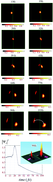 |
| | Fig. 4 With a static magnetic field applied of strength B = 2.5 T negative refraction of the wavepacket occurs. This is demonstrated in the time sequence t = 13–103 fs. A reflected ray emerges at the step on the left hand side of the boundary, whereas inside the step a negatively refracted transmission is seen. The maximum probability density, |Ψ1|2 is plotted as a function of time. At the boundary the probability density peaks. The inset of the plot shows the shape of |Ψ1|2 at 90 fs, when there is clear negative refraction. The directions of the trajectories are shown by arrows in this inset. In the plot at 103 fs, illustrative arrows show the curvature of the path of the wavepacket due to the applied magnetic field. The ratio of leviton energy to step height is α = 0.4. | |
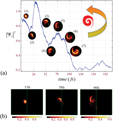 |
| | Fig. 5 A system of graphene, laid upon a quartz substrate, with a leviton/potential step energy ratio of α = E/Up = 0.4 is shown. The graphene layer is coloured black and the leviton propagates across its surface till it meets the potential at t ≈ 19 fs. The colour bar under each time iteration of the evolution indicates the maximum probability density, |Ψ1|2. Upon striking the step, a the wavefunction is reflected to produce a vortex state. In (a) its evolutionary shape is shown at (1) 13 ps, (2) 26 ps, (3) 45 ps, (4) 64 ps, (5) 77 ps, (6) 103 ps, and (7) 107 ps, as it circulates close to the step boundary. The vortex moves anti-clockwise, as is indicated by the large arrow in the top right of (a). In (b) snap-shots of the evolution of the development of the vortex are shown from t = 13 fs to 90 fs. The applied magnetic field is B = 6.5 T. | |
 |
| | Fig. 6 In (a) we show the maximum probability density as a function of time as the leviton meets the step for different values of α = E/Up. There is very little depreciation of |Ψ1|2 within the range α < 0.28, as is shown in (b) (red lines online). In (c) one can see |Ψ1|2 drops rapidly for α = 0.32 to 0.88 within the step, tending towards zero. In (d) at the ratio of leviton energy to step height, α ≥ 0.9, the system exhibits a phase change whereby |Ψ1|2 tends towards a continuous level. In (e) this trend has stabilised and plateaus (shown in purple online) emerge in the |Ψ1|2 evolution. These plateaus exist from α = 0.94 to 1.08. Beyond these values the quasiparticle lifetime begins to extend again (when the leviton energy is above that of the step), shown in (f). The colours of (a) are correlated with those of (b)–(f). In (d)–(f), the probability densities are shown from the right of the peaks of (a). The applied field is B = 5 mT. | |
 |
| | Fig. 7 The propagation through the step at 91 fs is shown at (a) α = E/Up = 1 and (b) α = 0.9. The colour bar indicates the level of |Ψ1|2. As α tends towards zero, the amplitude of the backscatter becomes smaller and smaller in the field of B = 5 mT. | |
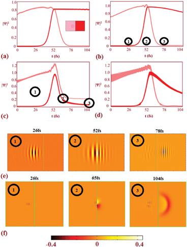 |
| | Fig. 8 The maximum probability densities before and in the step as a function of time are shown (pink and red lines, respectively) for (a) α = 0.16, (b) α = 0.4, (c) α = 1.0, and (d) α = 1.6 (for B = 5 mT). In (e) the wavepacket at α = 0.4 for 26 fs, 52 fs, and 78 fs can be seen. Likewise, in (f) snapshots of the evolution of the wavefunction at 26 fs, 65 fs, and 104 fs at α = 1 are given. | |
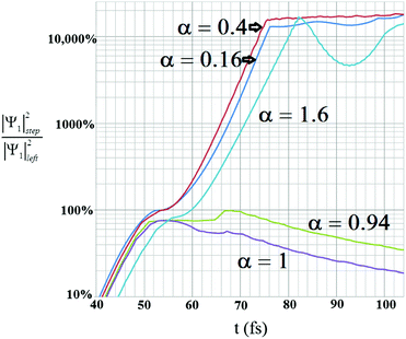 |
| | Fig. 9 The maximum probability densities either side of the step are presented as a ratio of the probability density in the step divided by that incident to the step. The result is found with a magnetic flux density of B = 5 mT. | |
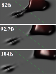 |
| | Fig. 10 The maximum probability densities either side of the step (central, green line) with α = 1.6 at 82 fs, 92.7 fs, and 104 fs. | |
4 Discussion and conclusions
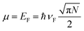
The leviton has been realised experimentally in the conventional two-dimensional electron gas (2DEG).2 The 2DEG that was realised in a GaAs/AlGaAs interface and studied by Dubnois and co-workers2 has a very high mobility and high electron density. The mobility in the samples they used is equal to μ = 2 × 106 cm2 V−1 s−1 and density ≈ 1.4 × 1011 cm−2. At such conditions in the 2DEG the Fermi liquid fixed point is well established. There levitons can be created due to an orthogonality catastrophe. As indeed they have been produced by Lorentzian-shaped voltage pulses applied on one of two electrodes located on the sides of the 2DEG. These pulses generate levitons that travel from the source electrode through the quantum conductor made of the 2DEG to the other electrode.
To directly reproduce the high mobilities found in a 2DEG an alternative method to those discussed within for producing levitons in graphene could be to use suspended graphene (see, the review39). Recently it was also indicated that epitaxial graphene bubbles may also have a very large mobility that is comparable to that of suspended graphene.40 There are a number of reasons for choosing to use graphene over a 2DEG, with the main difference between the two being that the electron transport in the graphene is relativistic.41So, the levitons created in graphene also have a relativistic character – they are moving with a constant velocity – “the speed of light”. Another important difference is that graphene has a quantum capacitance.39,40,42–46 It is related to the property of the graphene layer to accommodate the charge carriers. The quantum capacitance originates due to the strong dependence of graphene electron density N on chemical potential, μ. The density of states (DoS) in two-dimensional graphene depends linearly on the Fermi energy.39–42 Taking this into account one may obtain that the quantum capacitance is equal to:39–42
| |  | (10) |
where
A is the surface area of the graphene layer. At low temperatures, the dependence of the chemical potential (
i.e. the Fermi energy
EF) upon the electron density
N has the very simple form:
| |  | (11) |
Thus, the quantum capacitance remains proportional to the chemical potential μ, or to the gate voltage V(t), applied to the graphene layer. This means that when we apply voltage pulses to the graphene layer to create levitons we will change its capacitance (see the eqn (10), where in this case the value EF should be replaced by EF + V(t)). For graphene, the DoS on Fermi energy depends on the electron density N. This property differs to the conventional 2D systems where the DoS is constant. The quantum capacitance might have a significant impact on the creation and detection of levitons, which can be readily noticeable as arising with an additional capacitance effect on top of a constant electrostatic capacitance, when measurements of the differential capacitance subjected to different gate voltage pulses will be performed. We expect that levitons may also contribute to quantum compressibility, which was discussed recently for graphene in ref. 42–46.
We have shown that the leviton formed in single layers of graphene has many unique properties viable for applications. Electrons in graphene travel with an effective speed of light and high enough lifetime to see many new phenomena. There is an obvious analogy between tunnelling in graphene and refraction in optics.34,47 The Fermi energy level defines an effective index of refraction, which can be modified with the application of an applied magnetic field. In graphene, the height of the step modulates the transmission of the leviton and a curving of the trajectory occurs in the applied field. The degree of curvature increases with the field strength. We have demonstrated the behaviour of the leviton in small to moderate applied magnetic fields at various ratios of leviton energy divided by step potential. When the leviton approaches the potential with relatively small energy, and the step is large, there is nearly complete transmission. At an intermediate level of leviton energy/potential ratio there is also almost complete transmission, except one can see a larger backscattering off the step. This backscatter is universal below the height of the step and can exist even for low leviton Landau energies. Indeed, for these Gaussian types of soliton, transmission may be interpreted as Klein tunnelling26,48 in many cases, so low is the probability density of the backscattered wavefunction. Thus, it is highly likely that experiments would miss these reflected pulses. Closer to the top of the barrier, the backscattering is large and unmistakable. In this paper we have investigated a generalised step height that is constant as we have changed the energy of the encroaching soliton. In this approach, the Gaussian pulse changes as a function of the leviton energy. Alternatively, one can investigate starting with a constant energy and varying the height of the potential. The results for this are shown in the ESI.† The trajectory of the electron cannot be traced out over a well defined path,49 it is after all a wave. Thus, we have focused on the probability density of the wavefunction, which allows us to chart the movement of the electron through the step in greater clarity. We have plotted the maximum probability densities either side of the step and found the characteristic behaviour of leviton–anti-levition transition through the step. We found that a Gaussian shaped soliton evolves as it travels, spreading and lowering its probability density naturally. When it encounters a potential step it will behave as though there is little obstacle in its path, quantum mechanically tunnelling with very little backscatter, when α < 28. In the range 0.28 < α < 0.90 the backscatter becomes increasingly large, until when α > 0.90 the backscatter, in a small magnetic field such as B = 5 mT, becomes optimum. In the small magnetic field there is never complete reflection from the step when the trajectory begins at incidence. However, at larger magnetic fields this is not the case and almost complete reflection does occur (also see the ESI† animations). For larger magnetic fields the leviton slides up the potential step and forms a vortex: the levity vortex. Above the step, with small magnetic field applied, the backscattering also occurs when the leviton passes over in proximity to the maximum of the step potential. Therefore, in addition to controlling the leviton with the magnetic field we have extended the analysis to a complete picture of the propagation through the step in small magnetic fields. Klein tunnelling can be controlled by the strength of the magnetic field. Experimentally, the characteristic electronic relaxation time in mono-layer graphene was found by Carbone et al. to be 200 fs.50 We have demonstrated the leviton dynamics over a duration of 100 fs and beyond indicating that levitons formed in graphene have the potential to be used in radical new designs of waveguides and electronic devices. The studies of levitons in graphene may shed light on many-body Coulomb interactions between electrons. In general it was discussed that due to this interaction the value of the Fermi velocity is renormalized. Thus, the science of the leviton transport may be linked with understanding the Coulomb interaction in graphene. Moreover, levitons and levity vortices represent new quasiparticles. They may consist of even or odd numbers of fermions. Thus, the leviton may have the capability to satisfy either the Fermi or Bose statistics. Also, nothing prohibits levitons from having fractional statistics such as those for semions or anyons. But the most intriguing prospect is perhaps the possibility for levitons to form Majorana fermions: the particles which may themselves be their own anti-particles. Moving with the Fermi velocity in graphene, the value of which does not depend on doping, the leviton trajectory is a well defined path along which they may transmit coherently for very large distances. This may be used, for example, for establishing the quantum coherence or entanglement between qubits (the elements of quantum information), which can be embedded on graphene.
The authors thank the EPSRC for funding under KTA grant – “Developing prototypes and a commercial strategy for nanoblade technology”. They would also like to thank Dr V. Zalipaev for stimulating discussions.
References
-
A. T. Filippov, Versatile Solitons, Springer, New York, Dordrecht, Heidelberg, London, 2nd edn, 2010 Search PubMed.
- J. Dubois, T. Jullien, F. Portier, P. Roche, A. Cavanna, Y. Jin, W. Wegscheider, P. Roulleau and D. C. Glattli, Nature, 2013, 502, 659–663 CrossRef CAS PubMed.
- L. S. Levitov, H. Lee and G. B. Lesovik, J. Math. Phys., 1996, 37, 4845–4866 CrossRef PubMed.
- D. A. Ivanov, H. W. Lee and L. S. Levitov, Phys. Rev. B: Condens. Matter Mater. Phys., 1997, 56, 6839–6850 CrossRef CAS.
- J. Keeling, I. Klich and L. S. Levitov, Phys. Rev. Lett., 2006, 97, 116403 CrossRef CAS.
- A. K. Geim and K. S. Novoselov, Nat. Mater., 2007, 6, 183–191 CrossRef CAS PubMed.
- A. K. Geim, Science, 2009, 324, 1530–1534 CrossRef CAS PubMed.
- N. Savage, Nature, 2012, 483, S30–S31 CrossRef CAS PubMed.
- P. R. Wallace, Phys. Rev., 1947, 71, 622–634 CrossRef CAS.
- A. O'Hare, F. V. Kusmartsev and K. I. Kugel, Nano. Lett., 2012, 12, 1045–1052 CrossRef CAS PubMed.
- A. H. C. Neto and K. Novoselov, Rep. Prog. Phys., 2011, 74, 082501 CrossRef.
- F. Schwierz, Nat. Nanotechnol., 2010, 5, 487–496 CrossRef CAS PubMed.
- F. V. Kusmartsev and A. M. Tsvelik, JETP Lett., 1985, 42, 257–260 Search PubMed.
- F. Bonaccorso, Z. Sun, T. Hasan and A. C. Ferrari, Nat. Photonics, 2010, 4, 611–622 CrossRef CAS.
- K. S. Novoselov, A. K. Geim, S. V. Morozov, D. Jiang, Y. Zhang, S. V. Dubonos, I. V. Grigorieva and A. A. Firsov, Science, 2004, 306, 666–669 CrossRef CAS PubMed.
- S. D. Sarma, S. Adam, E. H. Hwang and E. Rossi, Rev. Mod. Phys., 2011, 83, 407–470 CrossRef.
- Y. B. Zhou, H. C. Wu, D. P. Yu and Z. M. Liao, Appl. Phys. Lett., 2013, 102, 093116 CrossRef PubMed.
- H. Yan, F. Xia, Z. Li and P. Avouris, New J. Phys., 2012, 14, 125001 CrossRef.
- V. V. Cheianov, V. Fal'ko and B. L. Altshuler, Science, 2007, 315, 1252 CrossRef CAS PubMed.
- H. Harutyunyan, R. Beams and L. Novotny, Nat. Phys., 2013, 9, 423–425 CrossRef CAS.
- J. C. Johannsen, S. Ulstrup, F. Cilento, A. Crepaldi, M. Zacchigna, C. Cacho, I. C. E. Turcu, E. Springate, F. Fromm, C. Raidel, T. Seyller, F. Parmigiani, M. Grioni and P. Hofmann, Phys. Rev. Lett., 2013, 111, 027403 CrossRef.
- K. Mita, Am. J. Phys., 2007, 75, 950 CrossRef.
- C. Hwang, D. A. Siegel, S.-K. Mo, W. Regan, A. Ismach, Y. Zhang, A. Zettl and A. Lanzara, Sci. Rep., 2012, 590 Search PubMed.
- J. H. Choi, G. H. Lee, S. Park, D. Jeong, J. O. Lee, H. S. Sim, Y. J. Doh and H. J. Lee, Nat. Commun., 2013, 4, 2525 Search PubMed.
- K. P. Loh, Q. Bao, P. K. Ang and J. Yang, J. Mater. Chem., 2010, 20, 2277–2289 RSC.
- M. I. Katsnelson, K. S. Novoselov and A. K. Geim, Nat. Phys., 2006, 2, 620–625 CrossRef CAS.
- R. Dean, A. F. Young, P. Cadden-Zimansky, L. Wang, H. Ren, K. Watanabe, T. Taniguchi, P. Kim, J. Hone and K. L. Shepard, Nat. Phys., 2011, 7, 693–696 CrossRef.
- K. S. Novoselov, Z. Jiang, Y. Zhang, S. V. Morozov, H. L. Stormer, U. Zeitler, J. C. Maan, G. S. Boebinger, P. Kim and A. K. Geim, Science, 2007, 315, 13799 CrossRef PubMed.
- A. S. Mayorov, D. C. Elias, I. S. Mukhin, S. V. Morozov, L. A. Ponomarenko, K. S. Novoselov, A. K. Geim and R. V. Gorbachev, Nano Lett., 2012, 12, 4629–4634 CrossRef CAS PubMed.
- A. Calogeracos, Nat. Phys., 2006, 2, 579–580 CrossRef CAS.
- V. V. Zalipaev, D. N. Maksimov, C. M. Linton and F. V. Kusmartsev, Phys. Lett. A, 2013, 377, 216–221 CrossRef CAS PubMed.
-
V. V. Zalipaev, D. M. Forrester, C. M. Linton and F. V. Kusmartsev, New Progress on Graphene Research, Chapter 2: Localised States of Fabry-Perot Type in Graphene Nano-Ribbons, Intech, 2013, pp. 29–79 Search PubMed.
- R. R. Hartmann, N. J. Robinson and M. E. Portnoi, Phys. Rev. B: Condens. Matter Mater. Phys., 2010, 81, 245531 CrossRef.
- J. R. Williams, T. Low, M. S. Lundstrom and C. M. Marcus, Nat. Nanotechnol., 2010, 6, 222–225 CrossRef PubMed.
- Q. Wu, J. P. Turpin and D. H. Werner, Light: Sci. Appl., 2012, 1, e38 CrossRef.
- C. A. Downing, D. A. Stone and M. E. Portnoi, Phys. Rev. B: Condens. Matter Mater. Phys., 2011, 84, 155437 CrossRef.
- D. A. Stone, C. A. Downing and M. E. Portnoi, Phys. Rev. B: Condens. Matter Mater. Phys., 2012, 86, 075464 CrossRef.
- X. Zhang, J. Xin and F. Ding, Nanoscale, 2013, 5, 2556–2569 RSC.
- K. C. Yung, W. M. Wu, M. P. Pierpoint and F. V. Kusmartsev, Contemp. Phys., 2013, 54, 233–251 CrossRef CAS.
- A. Ben-Gouider-Trabelsi, F. V. Kusmartsev, B. J. Robinson, A. Ouerghi, O. E. Kusmartseva, O. V. Kolosov, R. Mazzocco, M. B. Gaifullin and M. Oueslati, Nanotechnology, 2014, 25, 165704 CrossRef PubMed.
- A. Pototsky, F. Marchesoni, F. V. Kusmartsev, P. Hänggi and S. E. Savel'ev, Eur. Phys. J. B, 2012, 85, 356 CrossRef.
- G. L. Yu, R. Jalil, B. Belle, A. S. Mayorov, P. Blake, F. Schedin, S. V. Morozov, L. A. Ponomarenko, F. Chiappini, S. Wiedmann, U. Zeitler, M. Katsnelson, A. K. Geim, K. S. Novoselov and D. C. Elias, Proc. Natl. Acad. Sci. U. S. A., 2013, 110, 3282–3286 CrossRef CAS PubMed.
- Z. Chen and J. Appenzeller, Int. Electron Devices Meet., Tech. Dig., 2008, 110, 509–512 Search PubMed.
- J. L. Xia, F. Chen, J. H. Li and N. J. Tao, Nat. Nanotechnol., 2009, 4, 505–509 CrossRef CAS PubMed.
- J. L. Xia, F. Chen, J. L. Tedesco, D. K. Gaskill, R. L. Myers-Ward, C. R. Eddy, D. K. Ferry and N. J. Tao, Appl. Phys. Lett., 2010, 16, 162101 CrossRef PubMed.
- L. A. Ponomarenko, R. Yang, R. V. Gorbachev, P. Blake, A. S. Mayorov, K. S. Novoselov, M. I. Katsnelson and A. K. Geim, Phys. Rev. Lett., 2010, 13, 136801 CrossRef.
- P. E. Allain and J. N. Fuchs, Euro. Phys. J. B., 2011, 83, 301–317 CrossRef CAS.
- A. F. Young and P. Kim, Nat. Phys., 2009, 5, 222–226 CrossRef CAS.
- K. Huang, Am. J. Phys, 1952, 20, 479–484 CrossRef.
- F. Carbone, G. Aubock, A. Cannizzo, F. van Mourik, R. R. Nair, A. K. Geim, K. S. Novoselov and M. Chergui, Chem. Phys. Lett., 2011, 504, 37–40 CrossRef CAS PubMed.
Footnote |
| † Electronic supplementary information (ESI) available: Animations of the evolution of the levitons are included. See DOI: 10.1039/c4nr00754a |
|
| This journal is © The Royal Society of Chemistry 2014 |
Click here to see how this site uses Cookies. View our privacy policy here.  Open Access Article
 This Open Access Article is licensed under a
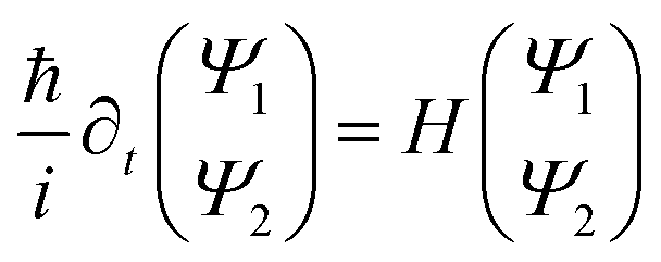
 is incorporated into eqn (1) and (2).This magnetic scale is equivalent to
  where B becomes a dimensionless parameter. We now write the dimensionless form of eqn (1),
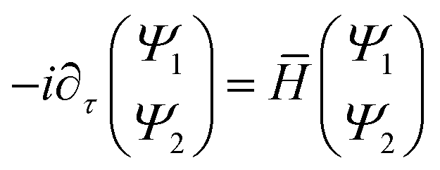
 . Throughout we will apply a Gaussian wavepacket to the system. In general a leviton could consist of many particles and conceivably have different shapes that could be self-consistently determined. In the present work we are interested in relativistic levitons in graphene, which may have similarities with point-like relativistic particles. For this purpose we have to construct a wavepacket that allows correspondence to a single quantum number. By way of reasonable approximation we consider a very narrow distribution of quantum numbers around the chosen one. It is believed that the best way to do this is for it to be described by a Gaussian distribution which corresponds (after a Fourier transform) to the Gaussian wave packet that is studied in this paper. Moreover, due to the same reason (the narrow range of quantum numbers) the Gaussian packet may in general be more stable than any other shapes of the wavepackets. Indeed, Mita showed that any non-Gaussian wavepacket takes a Gaussian shape as it disperses with time.22 Furthermore, in magnetic fields the electron wave function associated with a Landau level has a dominant Gaussian shape. That is why for levitons in magnetic fields the most natural choice is the Gaussian shape for the wavepacket under study. Of course the Lorentzian shape of the wavepacket is equally applicable to study levitons. However in this case, for the Lorentzian wavepacket, the distribution of the quantum numbers is significantly more broadly dispersed. Therefore, packets of non-Gaussian waveforms can create more noise at their detection (see, ref. 2). In addition, that may hide some other leviton features and transport characteristics. These arguments stimulated us to choose the Gaussian wavepackets as the most appropriate to study levitons in graphene. Here the leviton is formed with the height and width of a Gaussian wavepacket with initial given shape,
 . The energy associated with the leviton wavepacket is E = αŪp, where α denotes the ratio of the electron energy to that of the potential. The shape of the soliton is defined by ā and