 Open Access Article
Creative Commons Attribution 3.0 Unported Licence
Inkjet printed superparamagnetic polymer composite hemispheres with programmed magnetic anisotropy†
Olgaç
Ergeneman
*a,
Christian
Peters
b,
Maurizio R.
Gullo
c,
Loïc
Jacot-Descombes
c,
Simone
Gervasoni
a,
Berna
Özkale
a,
Philipe
Fatio
a,
Victor J.
Cadarso
c,
Massimo
Mastrangeli
c,
Salvador
Pané
a,
Jürgen
Brugger
c,
Christofer
Hierold
b and
Bradley J.
Nelson
a
aMulti Scale Robotics Lab, Institute of Robotics and Intelligent Systems, ETH Zurich, Tannenstrasse 3 CLA H15.2, 8092, Zurich, Switzerland. E-mail: oergeneman@ethz.ch
bMicro- and Nanosystems, ETH Zurich, Tannenstrasse 3 CLA H7, 8092, Zurich, Switzerland. E-mail: chpeters@ethz.ch
cMicrosystems Laboratory 1, EPFL, STI IMT LMIS1, BM 3115, Station 17, 1015, Lausanne, Switzerland. E-mail: juergen.brugger@epfl.ch
First published on 1st April 2014
Abstract
We present the fabrication and characterization of large arrays of inkjet-printed superparamagnetic polymer composite (SPMPC) hemispherical microstructures. SPMPCs are appealing for applications in microsystems and nanorobotics due to the added functionality of polymers and the significant magnetic attributes of embedded nanostructures. SPMPC-based microarchitectures can be used to perform different functions wirelessly in various media (e.g. water, solvents) using external magnetic fields: handling and assembling small objects, delivering drugs or biomass, or sensing specific physical or chemical changes. In this work superparamagnetic magnetite nanoparticles are dispersed in SU-8 to form magnetic hemispheres. Magnetically anisotropic hemispheres as well as standard SPMPC hemispheres are fabricated. Magnetic anisotropy is programmed by applying a magnetic field during curing. The distribution of nanoparticles inside the polymer matrix and magnetic characteristics of the SPMPC are investigated. Magnetic manipulation of hemispheres is demonstrated at liquid–liquid interfaces. Different assembly strategies to form lines or geometric shapes from hemispheres as well as their independent dynamic control are demonstrated. Finally, a two-interface assembly strategy is demonstrated to assemble hemispheres into complete spheres for advanced self-assembly tasks.
The trend of device miniaturization is one of the most significant concerns faced by process engineering and industry. As the systems are further miniaturized, machining of their parts becomes more complicated, requiring multidisciplinary knowledge and advanced manufacturing and assembly technologies.1,2 New approaches in fabrication have allowed machining more complex micro- and nanoarchitectures. The use of template-assisted fabrication (TAF) processes is one widely used strategy. In this approach, patterns or arrays made of inorganic or organic material serve as molds for the production of micro- and nanofeatures. This approach has already been proven for producing nanowires,3 nanotubes, honeycombs;4 and more complex geometries such as micro- and nanohelices.5 Anodic alumina and polycarbonate porous membranes, or patterns generated by photon, electron-beam and colloidal lithography are among the most widely utilized templates. However, there are some drawbacks in the use of TAF methods such as their limited resolution, the chemical stability of the patterns or the limited availability of achievable shapes. In contrast, template-free fabrication (TFF) processes are gaining importance due to their ability to form three-dimensional components. These methods do not require vacuum technology and the material waste during processing is significantly reduced. Some of the TFF methods include localized electrochemical deposition,6 electrohydrodynamic liquid ejection,7 dip-pen nanolithography, and inkjet printing.8
Inkjet printing is a promising technology to shape a wide variety of materials such as polymers, hydrogels, graphene or metal oxides.8 Some of the key benefits of this method are the rapid prototyping, non-contact multimaterial deposition, and low waste. Inkjet printing also allows machining a wide variety of shapes including pillar arrays, helices, zigzag patterns or microbridges.9 Recently, Jacot-Descombes et al. have reported the fabrication of well-defined hollow microspherical shapes10 on pre-patterned substrates and with microchip embedding.11 With suitable ink formulations, complex composite microstructures consisting of a matrix containing functional nanoparticles can also be manufactured.12 For example, Wood et al.13 showed the fabrication of inkjet-printed quantum dot–polymer composites for AC electroluminescent displays. Small and Panhuis reported the fabrication of electrically conductive composite patterns containing single-walled carbon nanotubes by inkjet printing for chemical sensing applications.14 In general, the main challenges of producing nanoparticle composites are controlling the dispersion of nanoparticles in the matrices and finding processing techniques for large volume manufacturing. Several methods allow patterning of nanocomposites such as photolithography, electrodeposition, and screen-printing.15–18 However, photosensitive fabrication methods are limited by the high UV absorption of the embedded nanoparticles.15,19 Electrodeposition requires always an electrochemically active matrix and a conductive substrate; and screen-printing exhibits low resolution. Solving these issues, inkjet printing can be a more advantageous fabrication route.
Magnetic polymer composites (MPCs) are appealing for applications in microsystems and nanorobotics due to the processability of the polymers and the enhanced magnetic attributes of embedded nanostructures.15,20,21 MPC-based microarchitectures can be used to perform several functions wirelessly using external magnetic fields: handling and assembling small objects,22 carrying and delivering drugs or biomass,21 or sensing specific physical or chemical changes.23 In addition, they can be actuated in different environments (i.e. air, solvents or electrolytes) provided they are magnetically transparent. Nevertheless, most reported magnetic micro- and nanocomponents are limited to simple actuation motions.16 In order to attain complex magnetic actuation, researchers have been working on several fabrication strategies. For example, Kim et al. showed the fabrication of superparamagnetic polymeric microcomponents with programmable magnetic anisotropy and they demonstrated actuation mechanisms that were not possible before. The embedded nanoparticles are aligned by applying magnetic fields to set a preferred magnetic direction (i.e. easy axis). Furthermore, Peters et al. showed that by applying magnetic fields during the fabrication of MPC-based helical swimmers by two-photon polymerization, the corkscrew propulsion of the microhelices could be significantly enhanced.17
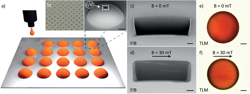
In this paper, we present the fabrication of large arrays of inkjet-printed superparamagnetic polymer composite (SPMPC) hemispherical microstructures (Fig. 1). Details of the fabrication can be found in the ESI.† Briefly, a dispersion of superparamagnetic nanoparticles of magnetite (Fe3O4, average diameter d = 11 nm) and the epoxy SU-8 monomer are mixed in appropriate ratios to obtain a stable ink. Hemispheres are printed on a substrate by controlled deposition of microdroplets. The curvature and the size of the hemispheres are adjusted by controlling the surface properties of the substrate and the number of drops printed as described in ref. 24 and 25. The 2 vol% particle concentration SU-8 composite is then thermally cured for cross-linking the polymer beyond the optical limit.15 This step allows fabrication of relatively thick structures. It is also shown that the magnetic axis of the hemispheres can be programmed during the synthesis by carrying out all the fabrication steps in the presence of a homogeneous magnetic field of 300 Oe. A normal and a magnetically anisotropic (MA) microhemisphere are shown in Fig. 1(b and d vs. c and e). The forced alignment of nanoparticles in the MA hemisphere and, hence, the preferred magnetization direction can be already recognized with the optical microscope (Fig. 1(e)).
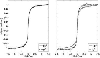
In order to explore the particle distribution across the polymeric hemispheres, focused ion beam (FIB) milling is performed. From the FIB cross-sections (Fig. 1(c)), one can observe that the distribution of particles in SPMPCs obtained without the magnetic fields is homogeneous,15 and only a few agglomerations are observed. In contrast, the cross-sections of MA hemispheres reveal that the lines of particles are parallel and separated by an approximate distance of 2 μm (Fig. 1(d)). These parallel patterns are also observed in other studies. For example, Sheparovych et al. showed that magnetite superparamagnetic nanoparticles stabilized in polyelectrolytes can form patterns of parallel wires when applying magnetic fields.26 This chain-like arrangement of nanoparticles is due to magnetic dipole–dipole interactions among them. Briefly, the application of a magnetic field overcomes the thermal motion that would otherwise annihilate the aggregation of the particles in an ordered manner. The magnetic properties of the hemispheres are also investigated by means of vibrating sample magnetometry (VSM). The normalized M–H curves for both samples are measured along two directions perpendicular to each other (Fig. 2). The curves labeled as 0° and 90° correspond to the magnetization of the hemispheres obtained when the field is applied parallel and perpendicular to the alignment direction of the nanoparticles, respectively. In all cases, the hemispheres exhibit a superparamagnetic behavior with no hysteresis. In principle, when the particles assemble into clusters with sizes higher than 15 nm, their single-domain character should vanish, thus becoming ferromagnetic.27 However, it is reported that big clusters also preserve their superparamagnetic attributes.28 The hemispheres obtained without the presence of a magnetic field show identical characteristics in both directions. By comparing the behavior of normal hemispheres with MA hemispheres, one can see that magnetization increases more rapidly with the field for MA hemispheres. This is in agreement with other studies29 in which it is observed that one-dimensional chains of magnetic nanoparticles react more sensitively to magnetic fields, because they perform as single-elongated particles or exhibit shape anisotropy due to interaction with each other.
To demonstrate their magnetic functionality, we show that self-assembly of the microfabricated hemispheres can be initiated and directed by magnetic fields and gradients. An easy and controlled way to manipulate these microhemispheres consists of performing the manipulation at liquid interfaces. Since the hemispheres are trapped at the interface, their motion is restricted to two dimensions. Moreover, the particles can be confined at the center of the liquid–liquid interface benefiting from the liquid menisci at the container walls. In our study, the hemispheres were manipulated in a water–decane interface in a cylindrical glass beaker with a diameter of 13 mm. A custom-made magnetic manipulation setup consisting of three orthogonal Helmholtz pairs was utilized (for details refer the ESI†). When the particles are trapped at the interface they tend to assemble due to strong capillary attraction, the so-called Cheerios effect.30 Lumay et al.31 studied the mechanisms of this phenomenon using ferromagnetic beads suspended in the air–water interface. By applying magnetic fields perpendicular to the interface, dipole–dipole repulsions between the beads are generated. By modulating the magnetic fields, the authors demonstrated that the interdistance between beads could be readily tuned.
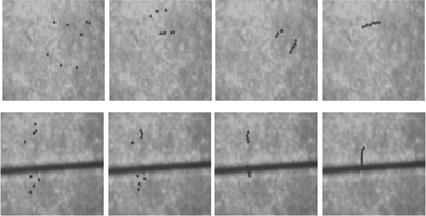
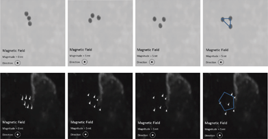
Fig. 3 shows two MA hemispheres under magnetic fields of different intensities and orientations. When two hemispheres are close to each other and a uniform field is applied perpendicular to the line connecting the centers of two hemispheres, the dipoles repel each other as captured in the first row. When the magnetic field is applied in line with the connecting line, the dipoles attract each other forcing particles to come together. This is shown in the second row of Fig. 3 (see SP1 video†). By applying gradients, the hemispheres or clusters of hemispheres can be moved around the workspace. By moving clusters and applying in-line magnetic fields, long chains of particles can be obtained as shown in Fig. 4 (see SP2 video†). These chains can be broken any time by suddenly changing the magnetic field direction of 90° causing magnetization of parts in parallel that induces a repulsive force. If the magnetic field direction is changed slowly the line of hemispheres will have time to follow the magnetic field rotating the assembly with the field. These manipulations can be observed in both normal and MA hemispheres with more effective results with the latter due to the stronger magnetic anisotropy.
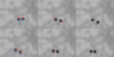 | ||
| Fig. 3 When two samples have parallel magnetization the dipoles repel each other (top image sequence). When they have in-line magnetization the dipoles attract each other (bottom image sequence). | ||
By applying out-of-plane magnetic fields the hemispheres can be magnetized in the applied field direction. The dipoles formed by the hemispheres will be parallel to each other and thus repel each other. An equilibrium can be found between the attractive capillary forces and the repulsive magnetic dipole forces as demonstrated by Lumay with ferromagnetic beads,31 and ordered structures can be obtained as shown in Fig. 5. Geometric patterns with controlled hemisphere interdistances can be obtained. Rotating magnetic fields cause dynamic movements of the hemispheres and they aid to break bonds when two hemispheres get together. This greatly helps their manipulation and high magnetic torques are only possible with MA hemispheres. They can be also utilized in functional machines. The normal hemispheres also exhibit a weak magnetic anisotropy due to agglomerations of nanoparticles or variations in their geometrical shape. To compare the two types of hemispheres, they are rotated with magnetic fields with increasing frequency of rotation. At step-out frequency the hemispheres cannot follow the magnetic field, because the rotational drag balances the magnetic torque. The MA hemispheres had a considerably higher step-out frequency of 125 Hz compared to normal ones which showed 65 Hz (repeated with >5 samples SD = 1 Hz). If these hemispheres are utilized in a microsystem where they perform a rotational movement, they can be addressed individually by the applied frequency. For example when a rotating field is applied at 100 Hz, the normal parts will stop while the MA hemispheres are rotating. SP3† shows the videos of the two types and their behavior under increasing frequencies.
Assembly of two hemispheres into a full sphere was also investigated. The two hemispheres can be made by different fabrication methods or carry different parts of a device. Two hollow hemispheres can also be assembled to encapsulate liquids.24,25 For this purpose, a two-interface system is designed with a decane–water–perfluorodecalin trilayer. First the perfluorodecalin–water interface is formed and a monolayer of hemispheres with their flat sides up is organized at this interface. Later, decane is added forming the second interface and another monolayer of hemispheres is assembled with their flat sides down this time. By applying magnetic fields assemblies are formed and centered with respect to each other. Using a micropipette, the intermediate phase (i.e. water) is slowly removed making the two layers come together. Fig. 6 shows the illustration of the two-interface assembly method and examples of assembled hemispheres (top right) and misaligned assemblies (bottom right). This process is a stochastic process and without any functionalization on hemispheres the yield is limited. However, this experiment demonstrates successful assemblies of hemispheres. By hydrophobic/hydrophilic functionalization the yield of this process can be significantly enhanced.24,25
In summary, SPMPC hemispherical microstructures with programmed anisotropy have been successfully fabricated using inkjet printing. This simple processing approach opens new avenues to manufacture components for microelectromechanical systems and nanorobotic tools. Magnetic microhemispheres can be successfully manipulated at liquid interfaces. Taking advantage of the magnetic interactions between the hemispheres, self-assembly of the hemispheres can be controlled in a wireless fashion using external magnetic fields. Patterns with more complex geometries can be fabricated.
Acknowledgements
The authors would like to thank Prof. Lucio Isa from ETH Zurich for his input on the experimental work, and Arif Zeeshan from ETH Zurich for help in FIB cuts. In addition the authors would like to thank Mouhamad Ali Freidy for working on some early steps of the project, as well as Dr K. Pataky and Dr V. Fakhfouri for installing the inkjet printing setup. This work has been scientifically evaluated by SNSF, financed by the Swiss Confederation, and funded by Nano-Tera.ch through the project “SELFSYS”.References
- X. Xiong, Y. Hanein and J. Fang, J. Microelectromech. Syst., 2003, 12, 117–127 CrossRef CAS.
- K. S. Park, X. Xiong, R. Baskaran and K. F. Böhringer, J. Micromech. Microeng., 2011, 21, 025002 CrossRef.
- M. Chong, Y. B. Zheng, H. Gao and L. K. Tan, Appl. Phys. Lett., 2006, 89, 233103–233104 CrossRef PubMed.
- J. Pokki, O. Ergeneman, K. M. Sivaraman, B. Ozkale, M. a. Zeeshan, T. Lühmann, B. J. Nelson and S. Pané, Nanoscale, 2012, 4, 3083–3088 RSC.
- M. A. Zeeshan, R. Grisch, E. Pellicer, K. M. Sivaraman, K. Peyer, J. Sort, B. Özkale, M. S. Sakar, B. J. Nelson and S. Pané, Small, 2013, 10, 1284–1288 CrossRef PubMed.
- E. Pellicer, S. Pané, V. Panagiotopoulou, S. Fusco, K. M. Sivaraman, S. Suriñach and M. D. Baró, Int. J. Electrochem. Sci., 2012, 7, 4014–4029 CAS.
- P. Galliker, J. Schneider, H. Eghlidi, S. Kress, V. Sandoghdar and D. Poulikakos, Nat. Commun., 2012, 3, 890 CrossRef CAS PubMed.
- E. Tekin, P. J. Smith and U. S. Schubert, Soft Matter, 2008, 4, 703 RSC.
- S. H. Ko, J. Chung, N. Hotz, K. H. Nam and C. P. Grigoropoulos, J. Micromech. Microeng., 2010, 20, 125010 CrossRef.
- L. Jacot-Descombes, M. R. Gullo, V. J. Cadarso and J. Brugger, J. Micromech. Microeng., 2012, 22, 074012 CrossRef.
- L. Jacot-Descombes, M. R. Gullo, M. Mastrangeli, V. J. Cadarso and J. Brugger, Micro Nano Lett., 2013, 8, 633–636 CAS.
- A. C. Balazs, T. Emrick and T. P. Russell, Science, 2006, 314, 1107–1110 CrossRef CAS PubMed.
- V. Wood, M. J. Panzer, J. Chen, M. S. Bradley, J. E. Halpert, M. G. Bawendi and V. Bulovic, Adv. Mater., 2009, 21, 2151–2155 CrossRef CAS.
- W. R. Small and M. in het Panhuis, Small, 2007, 3, 1500–1503 CrossRef CAS PubMed.
- M. Suter, O. Ergeneman, J. Zürcher, C. Moitzi, S. Pané, T. Rudin, S. Pratsinis, B. Nelson and C. Hierold, Sens. Actuators, B, 2011, 156, 433–443 CrossRef CAS PubMed.
- J. Kim, S. E. Chung, S.-E. Choi, H. Lee, J. Kim and S. Kwon, Nat. Mater., 2011, 10, 747–752 CrossRef CAS PubMed.
- C. Peters, O. Ergeneman, B. J. Nelson and C. Hierold, IEEE Int. Conf. Micro Electro Mech. Syst., 26th, 2013, 564–567 Search PubMed.
- M. Suter, L. Zhang and E. Siringil, Biomed. Microdevices, 2013, 15, 997–1003 CrossRef CAS PubMed.
- C. Peters, O. Ergeneman, G. A. Sotiriou, S. E. Pratsinis, B. J. Nelson and C. Hierold, Solid-State Sensors, Actuators and Microsystems, Transducers & Eurosensors XXVII: The 17th Int. Conf. on, 2013, pp. 2676–2679 Search PubMed.
- J. Thévenot, H. Oliveira, O. Sandre and S. Lecommandoux, Chem. Soc. Rev., 2013, 42, 7099–7116 RSC.
- W.-L. Chiang, C.-J. Ke, Z.-X. Liao, S.-Y. Chen, F.-R. Chen, C.-Y. Tsai, Y. Xia and H.-W. Sung, Small, 2012, 8, 3584–3588 CrossRef CAS PubMed.
- S. Tottori, L. Zhang, F. Qiu, K. K. Krawczyk, A. Franco-Obregón and B. J. Nelson, Adv. Mater., 2012, 24, 811–816 CrossRef CAS PubMed.
- O. Ergeneman, G. Chatzipirpiridis, J. Pokki, M. Marin-Suarez, G. A. Sotiriou, S. Medina-Rodriguez, J. F. F. Sanchez, A. Fernandez-Gutierrez, S. Pane and B. J. Nelson, IEEE Trans. Biomed. Eng., 2012, 59, 3104–3109 CrossRef PubMed.
- L. Jacot-Descombes, C. Martin-Olmos, M. R. Gullo, V. J. Cadarso, G. Mermoud, L. G. Villanueva, M. Mastrangeli, A. Martinoli and J. Brugger, Soft Matter, 2013, 9, 9931–9938 RSC.
- M. Mastrangeli, L. Jacot-Descombes, M. R. Gullo and J. Brugger, IEEE 27th Int. Conf. on Micro Electro Mechanical Systems (MEMS), 2014, pp. 56–59 Search PubMed.
- R. Sheparovych, Y. Sahoo, M. Motornov, S. Wang, H. Luo, P. N. Prasad, I. Sokolov and S. Minko, Chem. Mater., 2006, 18, 591–593 CrossRef CAS.
- V. Raman, A. Bose, B. D. Olsen and T. A. Hatton, Macromolecules, 2012, 45, 9373–9382 CrossRef CAS.
- R. Sondjaja, T. Alan Hatton and M. K. Tam, J. Magn. Magn. Mater., 2009, 321, 2393–2397 CrossRef CAS PubMed.
- K. Nakata, Y. Hu, O. Uzun, O. Bakr and F. Stellacci, Adv. Mater., 2008, 20, 4294–4299 CrossRef CAS.
- D. Vella and L. Mahadevan, Am. J. Phys., 2005, 73, 814 CrossRef.
- G. Lumay, N. Obara, F. Weyer and N. Vandewalle, Soft Matter, 2013, 9, 2420 RSC.
Footnote |
| † Electronic supplementary information (ESI) available. See DOI: 10.1039/c3nr06442e |
| This journal is © The Royal Society of Chemistry 2014 |

