Rice- and butterfly-wing effect inspired self-cleaning and low drag micro/nanopatterned surfaces in water, oil, and air flow
Gregory D.
Bixler
and
Bharat
Bhushan
*
Nanoprobe Laboratory for Bio & Nanotechnology and Biomimetics (NLB2), The Ohio State University, 201 W. 19th Avenue, Columbus, Ohio 43210-1142, USA. E-mail: bhushan.2@osu.edu
First published on 1st November 2013
Abstract
In search of new solutions to complex challenges, researchers are turning to living nature for inspiration. For example, special surface characteristics of rice leaves and butterfly wings combine the shark skin (anisotropic flow leading to low drag) and lotus leaf (superhydrophobic and self-cleaning) effects, producing the so-called rice and butterfly wing effect. In this paper, we study four microstructured surfaces inspired by rice leaves and fabricated with photolithography techniques. We also present a method of creating such surfaces using a hot embossing procedure for scaled-up manufacturing. Fluid drag, self-cleaning, contact angle, and contact angle hysteresis data are presented to understand the role of sample geometrical dimensions. Conceptual modeling provides design guidance when developing novel low drag, self-cleaning, and potentially antifouling surfaces for medical, marine, and industrial applications.
1. Introduction
Living nature thrives on effective designs while optimizing the use of precious resources, which is something that inspires engineers worldwide. Gaining a deeper understanding of living nature can lead to bioinspired products that save time, money, and lives. Examples include “low drag” boat hulls inspired by shark skin as well as “self-cleaning” windows and “antifouling” medical devices inspired by the superhydrophobic and low adhesion lotus leaf.1–7Common engineering challenges solved in living nature but hindering many industries are fluid drag,8–12 self-cleaning,4,13–15 and biofouling.16–21 Drag is the resistive force fluid imposes on an object in either open or closed channel flow (laminar or turbulent). Laminar flow appears smooth and orderly whereas turbulent flow appears chaotic and random – with drag generally higher in turbulent flow. Self-cleaning occurs when undesired liquids or contaminant particles are repelled or easily removed from a surface. Biofouling is the accumulation of unwanted organisms on a surface, with biofilms created by microorganisms and macroscale biofouling created by macroorganisms. In addition to biofouling, inorganic fouling can occur as a result of deposits from corrosion, crystallization, suspended particles, oil and ice.21
Many engineering applications in the medical, marine, and industrial fields can benefit from low drag, self-cleaning, and antifouling surfaces. Examples include airplanes,22 wind turbines,23 ship hulls,24 medical devices,25 and pipelines.18 Low drag surfaces often equate to less fouling which leads to energy conservation.13,15,21,26 For instance, in the oil industry, pipeline flow must overcome high drag due to viscous effects and possibly sludge fouling (with Reynolds numbers reaching 1 × 10⁵).27 Lower drag in pipelines reduces required pumping energy and increases flow rates. Normally, drag is lowered using fluid additives or improving the pipeline interior smoothness with corrosion resistant epoxy coatings.12,28–31 Such coatings are most effective when sludge fouling is not present, as found with oil flowing from a well at a high temperature and velocity.
Nature's self-cleaning methods are commonly associated with the lotus effect that combines superhydrophobicity and low adhesion, but can also include superhydrophilicity, as evident with pitcher plant.2,4,32–34 Self-cleaning occurs with the pitcher plant when water uniformly spreads and slides off carrying contaminants; whereas with lotus leaves water beads up and rolls off carrying contaminants.4,35 Similar self-cleaning mechanisms are possible with a variety of liquids, depending on the surface's ability to attract or repel the liquids. In addition to remaining free of contaminant particles, water repellent surfaces are reported to reduce ice adhesion in applications such as airplane wings, helicopter blades, oil platforms, power lines, locks and dams, and wind turbines.36,37
Low drag and antifouling surfaces have been the subject of many studies using shark skin inspired riblet surfaces. An ideal surface should withstand harsh environments, adhere to a variety of substrates, combine both low drag and antifouling properties, and be relatively inexpensive. Shark skin inspired products include the drag-reducing 3 M Corp. (Minneapolis, MN) experimental vinyl riblets38 as well as the Speedo FastSkin® fabric racing swimsuit. Such surfaces have been investigated by NASA, US Department of Energy, US Navy, Airbus, Boeing, as well as Olympic competitors. In the 1984 Los Angeles Olympics and 1987 America's Cup, 3 M riblets were applied to US boats, which presumably helped to secure victories. Although now banned from competition, the 2008 Beijing Olympics witnessed the benefit of the Speedo FastSkin® swimsuit when Michael Phelps set Olympic records and won several gold medals.39 Reportedly in open-channel water flow, drag is reduced by 13% with 3 M riblets39 and 4% with Speedo swimsuits.40 In an effort to create antifouling surfaces, the shark skin inspired Sharklet™ microtextured pattern has been developed and reportedly reduces biofouling.41–44
It was discovered that rice leaves and butterfly wings combine the desirable shark skin (anisotropic flow leading to low drag) and lotus leaf (superhydrophobic and self-cleaning) effects; creating the so-called rice and butterfly wing effect.26,45 Water droplets moving effortlessly on rice leaf and butterfly wing surfaces are shown in Fig. 1. These unique surfaces exhibit anisotropic flow, water repellency, self-cleaning, and low adhesion properties; which are believed to promote low drag, self-cleaning, and potentially antifouling. It is reported that sinusoidal grooves in rice leaves and aligned shingle-like scales in butterfly wings provide the anisotropic flow. Hierarchical structures consisting of micropapillae superimposed by waxy nanobumps in rice leaves and microgrooves on top of shingle like scales in butterfly wings provide the superhydrophobicity and low adhesion. Various studies suggest that this combination of anisotropic flow, superhydrophobicity, and low adhesion leads to improved drag reduction and self-cleaning.26,45
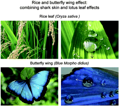 | ||
| Fig. 1 Rice and butterfly wing effect that combines the shark skin and lotus leaf effects. Shown are water droplets resting atop their superhydrophobic and low adhesion surfaces. Rice leaves contain longitudinal grooves with a transverse sinusoidal pattern and butterfly wings contain aligned shingle-like scales that provide anisotropic flow. Hierarchical structures consisting of micropapillae superimposed by waxy nanobumps in rice leaves and microgrooves on shingle-like scales in butterfly wings provide superhydrophobicity and low adhesion. This combination of anisotropic flow, superhydrophobicity, and low adhesion leads to improved drag reduction and self-cleaning.45 | ||
Producing cost efficient, low drag, self-cleaning, and antifouling surfaces may be possible by embossing patterns onto flexible adhesive backed polymer films. Such films could be applied to flat or curved substrates such as oil pipeline interiors, airplane wings, and ship hulls. Hot embossing may be conducted with a master mold that is heated and pressed into the polymer film. Fabricating embossed surfaces has been the subject of several studies46 and techniques range depending on the type of master mold and molding materials (i.e. composition, thickness, feature sizes). Master molds may include silicon,47,48 metal,49 and polydimethylsiloxane (PDMS).50 Molding materials may include polyvinylchloride (PVC)46 and commonly polymethylmethacrylate (PMMA).47,51–54 Embossing can be used to fabricate various structures including, for example, microfluidic flow channels,50,54,55 plastic microchips,51 and moveable microstructures.53 Such components are reported to yield sub-micron scale features.52,56
In the current study, rice leaf inspired samples have been fabricated using photolithography in the laboratory and experimentally evaluated for their drag reduction and self-cleaning effectiveness. The so-called rice leaf replica (which combines the unique shark skin and lotus effects), from a previous study,45 is being used as a baseline for comparison. In order to demonstrate the feasibility of scaled-up manufacturing, a hot embossing procedure was used to fabricate embossed polymer films. The embossed films are evaluated and their characteristics compared to samples fabricated by soft-lithography methods. Drag experiments are presented from closed channel water, oil, and air ranging from laminar to turbulent flows – which simulates conditions in medical, marine, and aerospace applications. The lotus effect is shown with self-cleaning, contact angle, and contact angle hysteresis measurements. Results are discussed and conceptual models are provided suggesting the effectiveness of rice and butterfly wing effect surfaces on drag reduction, self-cleaning, and thus antifouling.
2. Bioinspired designs
In this section, we explain mechanisms behind the shark skin, lotus, as well as the rice and butterfly wing effect surfaces. We also provide a brief overview summary of experimental results from open and closed channel fluid flow and self-cleaning experiments.2.1. Shark skin and lotus effects
In living nature, certain plants and animals thrive due to their low drag, self-cleaning, and antifouling characteristics.4,14,21,32,57–60 For example, the skin of fast swimming sharks exhibits low drag, self-cleaning, and antifouling properties; and lotus leaves exhibit self-cleaning and antifouling properties. It is believed that sharks require low drag skin in order to swim quickly to catch prey, and that antifouling is necessary in order to maintain the low drag. It is believed that since lotus plants thrive in humid, marshy environments, self-cleaning prevents unwanted fouling, which may inhibit photosynthesis.The shark skin relies on microstructured riblets on dermal denticles that reduce drag and prevent biofouling, as compared to other aquatic species. For instance, whales are often covered with barnacles; however sharks remain clean.39 The shark skin riblets are believed to increase water flow rate at the solid–liquid interface, which effectively lowers drag and prevents the buildup of biofouling. Naturally occurring turbulent vortices are lifted and presumably pinned, which is believed to lower fluid drag.1,39,59–68 In addition, microorganisms larger than the spacing between riblets are unable to effectively adhere to and ultimately colonize the skin, which further promotes antifouling.4,42–44,69
The lotus leaf relies on hierarchical micropapillae, which are described as microbumps superimposed with low surface energy waxy nanostructures,14,57 which provide self-cleaning properties. It should be noted that several other plant species also exhibit self-cleaning properties due to superhydrophobic and low adhesion characteristics. In nature, rain droplets impact the lotus leaf surface and effectively roll off due to the water repellency effect. This leads to self-cleaning, where droplets collect and remove any contaminant particles. The lotus effect relies on roughness induced superhydrophobicity and low adhesion, where air pockets are present at the solid–liquid interface.2–4,57,70
Fluid drag and self-cleaning experiments have been conducted with shark skin and lotus leaf inspired surfaces to study a variety of geometries, configurations, materials, fluids, and flow conditions (laminar and turbulent flow). Shark skin inspired riblet samples include blade, sawtooth, scalloped, and bullnose geometries with continuous and segmented (aligned and staggered) configurations in water, oil, and air.39 Open channel oil experiments with metal riblets show drag reduction of nearly 10%,63 whist closed channel water experiments with polymer riblets show pressure drop reduction up to 34%.45 Polymer shark skin replicas have also been evaluated, and have reduced pressure drop up to 30% in closed channel water flow.45,71 Experiments with lotus effect surfaces suggest reduced drag in laminar45,71,72 and turbulent flows.45,71,73–75 Furthermore, it is reported that closed channel pressure drop is proportional to velocity and nondimensional pressure drop is proportional to the Reynolds number; therefore pressure drop may be estimated when fluid properties, flow conditions, and channel dimensions are known.45 Additionally, self-cleaning experiments have been conducted using micro-sized silicon carbide contaminant particles. Water droplet wash experiments show maximum contaminant removal of 79% for the shark skin replica26 and 99% for the lotus leaf replica.13
2.2. Rice and butterfly wing effect
In addition to lotus leaves, rice leaves and butterfly wings also exhibit lotus effect characteristics. It is believed that since rice plants thrive in humid, marshy environments, self-cleaning prevents unwanted fouling, which may inhibit photosynthesis.26 Since butterflies are fragile and unable to clean their wings, these properties are critical to maintain structural coloration and flight control.76 Both rice leaves and butterfly wings exhibit unique anisotropic flow characteristics, where droplets roll down the blade of the rice leaf and axially away from the butterfly body.26Shown in Fig. 2a are the hierarchical structures of both the rice leaves and butterfly wings that provide the anisotropic flow, superhydrophobicity, and low adhesion properties. Anisotropic flow is facilitated by the longitudinal grooves with a transverse sinusoidal pattern in rice leaves and aligned shingle-like scales in butterfly wings. Superhydrophobicity and low adhesion is facilitated by micropapillae superimposed by epicuticular waxy nanobumps in rice leaves77–81 and hierarchical scales with microgrooves on butterfly wings.26,76,82–84 The combination of anisotropic flow, superhydrophobicity, and low adhesion is reported to reduce drag and facilitate self-cleaning.26,45 This unique combination is the reported combine shark skin and lotus leaf effects, which are believed to be found with butterfly wings and rice leaves. Simplified conceptual models of rice leaf and butterfly wing microstructures are shown in Fig. 2b. The water droplets sit above the hierarchical surface structures and can effortlessly roll and collect contaminants to improve self-cleaning efficiency.26,45
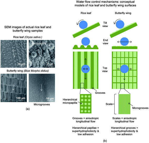 | ||
| Fig. 2 (a) Montage of SEM images depicting actual self-cleaning rice leaf and butterfly wing surfaces (adapted from ref. 26). (b) Water flow control mechanisms: conceptual models of rice leaves and butterfly wings highlighting the hierarchical structures and their roles (adapted from ref. 26). Each example contains mechanisms that are believed to promote low drag, self-cleaning, and thus antifouling. Arrows indicate the tendencies of fluid flow in transverse and longitudinal directions. | ||
Previous rice and butterfly wing effect experiments have utilized a variety of configurations, fluids, coatings, and flow conditions.26,27,45 The greatest drag reduction benefit is demonstrated in turbulent water flow; where the maximum pressure drop reduction occurs with superhydrophobic rice leaf replicas at 26%.26 Also reported is a 10% pressure drop reduction using both the superoleophilic (typical oil film with CA < 10°) and superoleophobic (CA > 150°) coated rice leaf replica samples in laminar white paraffin oil flow.27,45 The rice leaf replica with the nanostructured superhydrophobic coating exhibits low adhesion, as measured with an Atomic Force Microscope (AFM) and shown with very low contact angle hysteresis, which is believed to further reduce drag.26 Additionally, self-cleaning experiments have been conducted with rice leaf inspired surfaces using micro-sized silica contaminant particles. Water droplet wash experiments show maximum contaminant removal is 95% for the rice leaf replica.26
2.3. Golden Ratio
The Golden Ratio and Fibonacci numbers have intrigued both scientists and artists for centuries, which may have led to the first bioinspired designs. The Golden Ratio is a unique ratio whose proportions are considered ideal from functionality and aesthetics standpoints. It is found throughout nature, with examples ranging from the human body proportions to the shapes of seashells and the Milky Way galaxy. Inspired by beauty found in nature, famous artists have included the Golden Ratio in their own works, such as Leonardo da Vinci in “a head of an old man” and “Mona Lisa.” It is defined as where the values height and width are non-dimensional lengths with height > width.85–87
Examining Golden Ratio and Fibonacci numbers with regards to low drag, self-cleaning, and antifouling surfaces may help reveal clues for understanding nature's methods. For instance, it was reported that butterfly wing scales measure 75 μm wide by 125 μm long.26 Dividing the values provides the ratio equaling 1.67, which correlates approximately to the Golden Ratio of 1.618.27 The scales effectively overlap in a shingle like manner with the longer edge in the fluid flow direction. This arrangement is believed to help encourage the desired anisotropic flow away from the butterfly body along the wings which leads to self-cleaning. We speculate that Golden Ratio and Fibonacci numbers may provide further clues and guidance for designing low drag, self-cleaning, and antifouling surfaces.45
3. Experimental methods
In this section, we explain the origin of the new rice leaf inspired surfaces, sample fabrication processes, and experimental apparatuses which provide drag, self-cleaning, contact angle, and contact angle hysteresis measurements.3.1. Bioinspired rice leaf surfaces
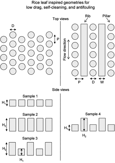
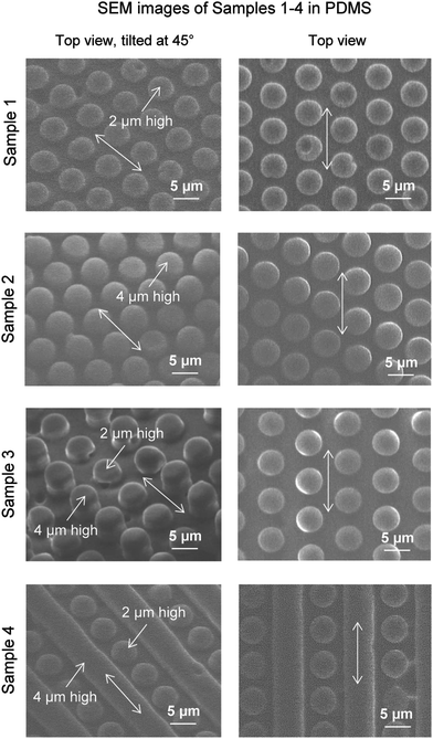
By studying nature's secrets to design and fabricate low drag, self-cleaning, and antifouling surfaces, the rice leaf is particularly intriguing due to its relatively simple micropapillae morphology. For instance, bioinspired rice leaf surfaces using micro-sized pillar patterns can be produced with silicon master patterns fabricated by photolithography. Sample geometrical dimensions are based on actual rice leaf morphology shown in Table 1. Actual rice leaf surfaces are covered by a sinusoidal pattern of micropapillae with height 2–4 μm, diameter 2–4 μm, pitch 5–10 μm, and peak radius 0.5–1 μm. Bioinspired rice leaf surfaces shown in Fig. 3 were created to study the rice and butterfly wing effect, and were designed to include anisotropic flow and superhydrophobic characteristics. The arrows indicate fluid flow direction for maximum drag reduction. Geometrical dimensions are shown in Table 2 with pillar height, pillar diameter or rib width, and pitch. Samples 1 and 2 represent just the pillars found in actual rice leaf patterns with pillar heights of 2 and 4 μm, respectively with a pillar diameter of 5 μm and pitch of 7 μm. Sample 3 represents the bioinspired rice leaf surface with dual height pillars selected to create a sinusoidal pattern whereas in Sample 4, the surface is created with a combination of 2 μm high pillars and 4 μm high ribs. Dual height features in Samples 3 and 4 create a hierarchical structure that is believed to facilitate the anisotropic flow similar to the sinusoidal grooves in actual rice leaves. Sample 3 most closely simulates rice leaf micropapillae morphology whereas Sample 4 includes pillars plus ribs to further enhance anisotropic flow. These designs were developed based on available microfabrication techniques to produce master patterns in silicon wafers.| Sample | Actual | ||||||
|---|---|---|---|---|---|---|---|
| Description | Vertical-dim (μm) | Transverse-dim (μm) | Longitudinal-dim (μm) | Pitch (μm) | Peak radius (μm) | ||
| Rice leaf (Oryza sativa) | Sinusoidal grooves array covered with micropapilla and nanobumps | Grooves | 125–150 | 150–175 | Full length | n/a | n/a |
| Micropapillae | 2–4 | 2–4 dia | n/a | 5–10 | 0.5–1 | ||
| Butterfly wing (Blue Morpho didius) | Shingle-like scales with aligned microgrooves | Scales | 30–50 | 50–75 | 100–125 | 50–75 | n/a |
| Microgrooves | 1–2 | 1–2 | 100–125 | 2–4 | 0.5–1 | ||
| Description | Height (H1 or H2) (μm) | Pillar diameter (D) or rib width (W) (μm) | Pitch (P) (μm) | |
|---|---|---|---|---|
| Sample 1 | Hexagonal array of single height pillars | 2 | 5 | 7 |
| Sample 2 | 4 | |||
| Sample 3 | Alternating rows of dual height pillars | 2 and 4 | ||
| Sample 4 | Alternating rows of single height pillars & ribs | 2 (pillars) 4 (ribs) |
Pitch length of the microstructured features found in Samples 1–4 resembles that of actual rice leaves, in order to promote the so-called thin film effect and potentially antifouling.27 The thin film effect is believed to occur when a thin layer of oil is held stationary at the solid–liquid interface, which is believed to lower drag.27 Pillars just tall and close enough to develop the thin film are necessary; however pillars too tall or far apart will impede fluid flow and thus increase the drag. Averaging the actual rice leaf micropapillae pitch length yields the pitch length of 7 μm for Samples 1–4. It is believed that antifouling is possible when the gap between features is less than the approximate diameter of fouling microorganisms.41–44 For Samples 1–4, the pitch is 7 μm and thus the gap is 2 μm, which is expected to provide antifouling of microorganisms that measure approximately 2–5 μm in diameter.
3.2. Silicon master patterns
Fabricating bioinspired rice leaf surfaces with micro-sized features requires microfabrication techniques in order to achieve the desired dimensions and tolerances. As such, Samples 1–4 were fabricated using silicon master patterns (fabricated by TRICR Corp., San Francisco, CA) and soft-lithography techniques. Solid models of Samples 1–4 were designed using computer aided design software by Solidworks® (Dassault Systèmes SolidWorks Corporation, Waltham, MA) with the scale set in microns. A single square photomask (130 mm × 130 mm × 2.3 mm thick with the critical dimensional tolerance of ±0.025 microns) was produced containing each pattern for Samples 1–4. The photomask was soda lime with low reflectance chrome plating showing pillars represented as transparent features on a solid background. Silicon master patterns for Samples 1–4 were created on separate 4′′ (10.16 cm) round silicon wafers with sample areas measuring 6 mm by 100 mm. The etching procedure included standard wafer dehydration, wafer prime, resist coating, wafer exposure, post exposure bake, wafer development, and hard bake. Tolerances include a 10% positional feature and ±0.25 micron pit depth tolerance.Silicon master patterns with pits (negative vs. positive features) were fabricated in order to emboss polymer films and to accurately produce master patterns. Embossing protrusions onto polymer films using master patterns is possible when the master pattern contains pits. In addition, pits are less challenging to fabricate as compared to protrusions for the dual height features of Samples 3 and 4. For instance, to create protrusions with two heights, all protrusions would need etched to the taller height using one photomask pattern, and then the shorter protrusions would need etched again with a second photomask pattern. Difficulty arises due to challenges of aligning the second photomask pattern to further etch to the shorter heights. Tolerances exist in both the photomask and alignment procedures which significantly increase the possibility of defects. This is not the case when etching two pit depths, which does not require the alignment of the second photomask pattern on top of existing protrusions. Instead, each pit depth is created with the same photomask pattern realigned and with different etching times.
3.3. Urethane soft lithography procedure
Fabricating rice leaf replica surfaces with micro-sized features was performed with a two-step soft lithography procedure. For the rice leaf replica, this procedure and a nanostructured coating was utilized in order to mimic actual rice leaves.26 Using liquid platinum silicone (Smooth-On Dragon Skin 20), a negative mold was taken after cleaning the actual rice leaf sample with deionized water and isopropyl alcohol. The liquid silicone ensured that details were accurately replicated and that air bubbles would rise away from the molding surface. With the silicone mold complete, liquid urethane polymer (Smooth-On Smooth-Cast 305) was applied and cured, yielding a precise positive replica.26For the nanostructured superhydrophobic coating, silica particles were selected as they are known to provide high durability and transparency, if desired.88,89 Rice leaf replicas were dip-coated with an ultrasonic mixed solution consisting of 50 nm (±15 nm) hydrophobized silica nanoparticles (by Evonik-Degussa Corporation, Parsippany, New Jersey) combined with methylphenyl silicone resin (SR355S from Momentive) dissolved in tetrahydrofuran and isopropyl alcohol.26
3.4. PDMS soft lithography procedure
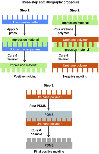
Fabricating rice leaf bioinspired surfaces with micro-sized features was performed with a three-step soft lithography procedure. For Samples 1–4, this procedure was utilized in order to produce samples from the silicon master patterns, as illustrated in Fig. 4 with Steps 1–3. The material polydimethylsiloxane (PDMS) (184 Silicone Elastomer by Dow Corning) was chosen due to its low surface energy property which leads to high contact angle. However, PDMS bonds well to bare silicon wafers and to itself, so therefore it was necessary to consider de-molding options for the soft lithography procedure. Using PDMS, various soft lithography techniques include the so-called double-casting method using PDMS on PDMS90 and polyurethane or epoxy master molds.91 Mold release options included using a mono-layer release agent coating (deposited for example via vapor deposition) or a molding material with additives that readily de-molds from PDMS.It was discovered the mono-layer release agent technique required significant effort to separate PDMS from the silicon wafer, and risked breaking the fragile wafer. Therefore the second technique was employed, as shown with Step 1, which entailed using a molding material that does not adhere well to silicon wafers. The hydrophilic vinyl polysiloxane impression material (Examix™ Type 3 low viscosity by GC America Inc.) met these criteria and was selected to create positive master molds. First, the silicon master pattern was cleaned using acetone and isopropyl alcohol rinses with nitrogen drying. The impression material was deposited directly onto the silicon master pattern via cartridge gun and mixing nozzle, gently pressed with a flat block, and cured at room temperature for 4 hours.
Next, Step 2 entailed utilizing the positive molds in dental impression material to create negative molds in urethane material. Liquid urethane polymer (Smooth-On Smooth-Cast 305) was chosen due to its dimensional stability, ease of casting, ability to de-mold easily from the dental impression material, and ability to de-mold from PDMS in Step 3. The liquid urethane was applied and cured, yielding precise negative master molds. Finally, Step 3 entailed utilizing the negative molds in urethane to create final samples in PDMS. Liquid PDMS was manually mixed, poured onto the urethane negative master molds, and allowed to cure at room temperature for 48 hours. The liquid PDMS remained in the liquid-form for at least 12 hours of the 48 hours duration, therefore allowing any air bubbles to effectively escape. The final samples in PDMS readily de-molded from the urethane negative master molds. Step 3 was repeated several times in order to produce the necessary quantity of samples in PDMS.
3.5. Hot embossing procedure
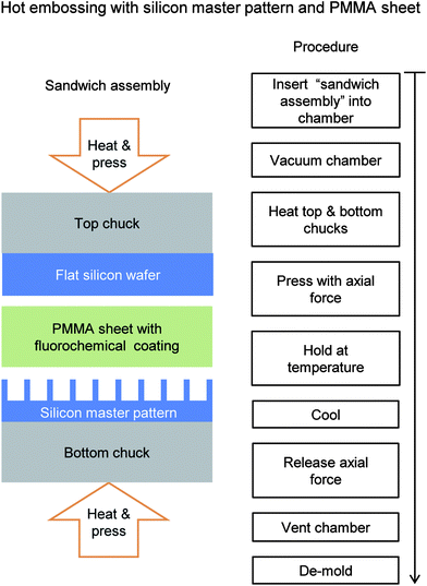
Fabricating rice leaf bioinspired surfaces with micro-sized features was also performed with an embossing procedure to demonstrate scaled-up manufacturing. Embossing polymer films was conducted using a commercial hot embossing machine (model EVG 520, S/N S050007, software V.7.01.00.00) in a clean room environment at the Nanotech West facility (The Ohio State University, Columbus, OH). Sample 3 was selected to be embossed for further evaluation due to its superior drag and self-cleaning properties in PDMS, as presented later. The hot embosser produces single-sided embossed polymer films from silicon master patterns using a combination of heat and pressure. The polymer films were selected to be optically clear 175 μm thick acrylic film based upon PMMA and acrylic elastomers (Evonik Cyro ROHAGLAS® 99524). PMMA molds relatively easily due to its low softening temperature point and the 175 μm thickness was deemed sufficient for embossing 4 μm tall features. The sandwich assembly shown in Fig. 5 consists of a 4′′ (10.16 cm) round silicon master pattern on the bottom, 4′′ (10.16 cm) round PMMA sheet in the middle, and 4′′ (10.16 cm) round flat silicon wafer on the top. The PMMA film and silicon wafers were thoroughly cleaned using acetone and isopropyl alcohol rinses with nitrogen drying prior to assembly.The PMMA film required a low surface energy coating on both sides for proper de-molding from the silicon master patterns and flat silicon wafers. The aqueous fluorochemical Capstone™ ST-100 (Dupont) was selected and diluted to 12% by volume with deionized water and mixed using an ultrasonic mixer. A spray deposition method was chosen for a uniform thin coating by using an internal mixing double action airbrush (model VL-SET, Paasche) and laboratory air at 30 psi.
The hot embossing procedure was developed from previous studies47 as well as trial and error (investigating suitable pressures, temperatures, hold times, release coatings, PMMA thickness) to ensure desired outcomes. Once assembled, the hot embosser chamber was vacuumed to 40 Torr (50 mbar) and the top and bottom chucks heated in order to soften the material. The PMMA has a Vicat softening point of 100 °C (Cyro Industries), therefore chucks were heated to 150 °C to ensure proper polymer softening. Once heated, an axial clamping force was applied and increased in increments of 2000 N to 10![[thin space (1/6-em)]](https://www.rsc.org/images/entities/char_2009.gif) 000 N with a hold time of 15 seconds at each step. At the maximum load, the clamping force was maintained for 10 minutes. Upon completion, the sandwich assembly was cooled to 80 °C and then the clamping force was released and the chamber vented to atmospheric pressure. De-molding was possible using a razor blade around the edges without fracturing the silicon master patterns.
000 N with a hold time of 15 seconds at each step. At the maximum load, the clamping force was maintained for 10 minutes. Upon completion, the sandwich assembly was cooled to 80 °C and then the clamping force was released and the chamber vented to atmospheric pressure. De-molding was possible using a razor blade around the edges without fracturing the silicon master patterns.
3.6. Pressure drop measurements
For the various experiments reported in this paper, the general size of the closed channel was based on hospital catheter tubes (3–5 mm diameter) commonly used in the healthcare industry to transport aqueous fluids. With a smaller catheter-sized closed channel, considerations included the difficulty of applying the samples inside of a channel. For this reason, the rectangular channel sandwich design was chosen, where samples were applied to one side and then sandwiched together to create a rectangular closed channel. The top side is a milled channel and the bottom side contains the sample.In order to measure fluid drag via pressure drop, an experimental apparatus was fabricated according to the schematic illustrated in Fig. 6.39 To achieve desired Reynolds numbers, experiments were conducted with an elevated container, syringe pump (New Era Pump Systems NE-300), and laboratory air. The two sample flow channel halves were carefully aligned, sealed with gaskets, clamped, and then purged of air bubbles (for water or oil flow). Each sample was measured with a light microscope and calipers to ensure accurate flow rate and theoretical pressure drop measurements.
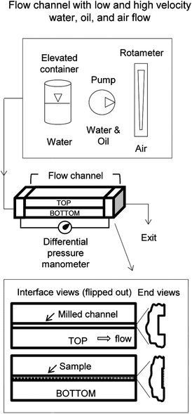 | ||
| Fig. 6 Closed channel methods and apparatuses to measure drag via pressure drop using water, oil, and air (adapted from ref. 39). The split rectangular channel design allows for samples to be fabricated inside the channel. Interface views are shown highlighting the top and bottom halves that are sandwiched together. Flow is regulated with the elevated container (water), pumps (water or oil), and laboratory air connected to a rotameter (air). The pressure drop is measured with a manometer connected to both ends of the flow channel. | ||
For water experiments, purified water was pumped from a reservoir to the elevated container, which then flowed down the supply line. To ensure a constant flow rate, the control valve and overflow line regulated the water level and the flow rate (thus Re) was varied by changing the container elevation. The syringe pump provided water flow at low velocities (0.04–0.09 m s−1) whilst the elevated container provided water flow for the high velocities (2–4.5 m s−1).26 For oil experiments, white paraffin oil (Carolina CAS number 8012-95-1) was selected due to its low surface tension, chemical compatibility with samples, and low health hazard. This selection and criteria are similar to the oil used in the so-called Berlin oil channel.92 To achieve a wide range of constant flow rates, oil was pumped into the closed channels using a syringe pump and a miniature gear pump (Cole-Parmer EW-07012-30). The syringe pump provided oil flow at low velocities (0.02–0.09 m s−1) whilst the gear pump provided oil flow for the high velocities (3.5–4.5 m s−1).27 For air experiments, laboratory air connected to an adjustable rotameter (Omega FL-1478-G) allowed for incremental variation of the flow velocity (4–33 m s−1). The laboratory airflow velocity was calculated based on the rotameter reading and the channel cross sectional area.26
To maintain kinematic viscosity with water and oil, fluid temperature was monitored with a digital thermometer (CND DTQ450X), and held constant (between 20° and 21 °C). The pressure drop between the inlet and outlet was measured with a differential manometer (Omega PX26-005DV) potted in RTV silicone. Data was collected at 10 Hertz for 30 seconds with an amplifier (Vishay 2311) and data acquisition card (Measurement Computing USB-1208LS). The system was calibrated prior to use with a pneumatic pressure system (Ametek RK-1600W6).
3.7. Predicting closed channel pressure drop
Comparing predicted pressure drop to the measured values can ensure that the system is behaving properly by detecting leaks and misalignments. This can be done by comparing the milled experimental sample channel to the predicted values. It also allows for a baseline comparison when reporting pressure drop percentage values. Predicting pressure drop of a flat rectangular duct requires use of the incompressible flow equations for straight uniform pipes. Since the Mach number is less than 0.3 for all experiments, incompressible flow equations may be used.9 The predicted pressure drop was calculated using the total channel cross-sectional area.Pressure drop (Δp) between two points in a flat hydrophilic straight uniform closed channel with incompressible and fully developed flow is found with the Darcy–Weisbach formula:9
 | (1) |
The friction factor for rectangular duct flow is:
 | (2) |
| k = 64 | (3a) |
 | (3b) |
The rectangular closed channel hydraulic diameter is:
 | (4) |
Eqn (1)–(4) are used to predict the pressure drop for the rectangular closed channels, as presented later for experiments with water, oil, and air (where b/a = 1.5 mm/3.3 mm = 0.45).45eqn (3b) shows the friction factor is dependent on channel geometry and independent of the surface roughness. In order to account for roughness, friction factor values for pipes can be estimated with the Moody chart.93
3.8. Self-cleaning measurements
To understand the self-cleaning effectiveness of Samples 1–4, experiments were conducted by contaminating the samples, employing a wash technique, and determining the percentage of particles removed. Depositing contaminate particles on the tilted (45°) replicas involved a glass contamination chamber (0.3 m in diameter and 0.6 m high), as shown in Fig. 7a. A tray containing 0.2 g of hydrophilic silicon carbide (SiC) contaminants (400 mesh particle size by Aldrich, with sizes ranging from 10–15 μm) was placed in the top chamber with an air hose directed in the center. These particles were chosen because of their similar properties to natural dirt (shape, size, and hydrophilicity). Contaminants were blown with laboratory air for 10 seconds at 300 kPa, and then allowed to settle for 30 seconds before the separator panel was removed. After 30 minutes, the samples were removed and subjected to pre-wash experiment particle analysis. Using a light microscope and CCD camera (Nikon, Optihot-2), a 280 μm by 210 μm area of each sample was imaged and analyzed with image processing software (SPIP 5.1.11, Image Metrology A/S, Horshølm, Denmark). The software recognizes contaminating particles as dark areas and counts the total number. This process was performed before and after each wash experiment.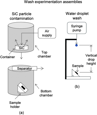 | ||
| Fig. 7 Schematic of particle contamination chamber to uniformly contaminate samples for wash experimentation (adapted from ref. 26). Two halves of the apparatus assemble to create the chamber, where silicon carbide (SiC) particles are dispersed with high pressure air flow into the top chamber. The separator door is removed and particles settle below onto the samples. (b) Schematic of wash experimentation apparatus. Water droplets at known velocities and flow rates impact the contaminated sample. Particle analysis is conducted to quantify self-cleaning efficiency. | ||
Wash experiments consisted of exposing the tilted (45°) replicas to water droplets falling from a specified heights and drip rates (total duration of 2 min using 10 mL water @ 20 < temp. < 21 °C). The syringe pump and tubing was positioned relative to the replica samples as shown in Fig. 7b.26 Droplet velocities reflect flow rates found in laminar through turbulent flow regimes, with velocities approximating 1 and 5.6 m s−1 at heights of 0.02 and 0.4 m, respectively. This translates into pressures of 200 and 4000 Pa, respectively.
3.9. Wettability
To understand the effects of wettability, the apparent contact angle (CA) and contact angle hysteresis (CAH) was measured for Samples 1–4. This was performed with water and oil droplets in air; and for completeness oil droplet CA was measured underwater. Water droplets approximately 1 mm in diameter (5 μL) were deposited and measured with an automated goniometer (Rame-Hart model 290-F4). Similar sized oil droplets were deposited using a microliter syringe (Hamilton model 701 with volume 10 μL). CAH was determined by tilting the sample until the droplet began to move (up to 90°), and subtracting the advancing and receding contact angles.The experimental apparatus in Fig. 8 was necessary to determine CA measurements at the solid–water–oil interface. With the density of white paraffin oil (880 kg m−3) lower than water (1000 kg m−3),94 the oil droplet needed to be deposited with the sample inverted. Such data is useful when considering self-cleaning efficiency of underwater surfaces contacting oil, or vice versa, where superoleophobicity may repel contaminants. Clean surfaces encourage low drag, so therefore self-cleaning is necessary for underwater applications where oil contaminants are present.45
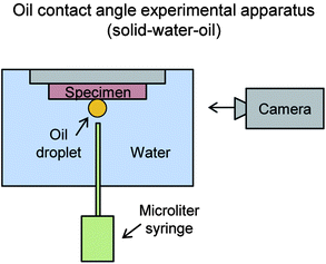 | ||
| Fig. 8 Experimental apparatus to measure the apparent contact angle at the solid–water–oil interface (adapted from ref. 27). Samples are inverted and submerged into water with the oil droplet deposited onto the surface via micro syringe. Since lower density oil floats in water, the oil droplet is deposited in the shown orientation. | ||
4. Results and discussion
In this section, we present images and measurements characterizing the actual rice leaf, replica rice leaf, Samples 1–4, and Embossed sample 3. Presented are measurements of various features describing surface morphology and replication success. Also included are drag measurements and mechanisms for water, oil, and air flow. Plots are shown from oil, water, and air drag experiments with the trend lines fitted through the origin. Also presented are results from self-cleaning, CA, and CAH experiments. Finally, conceptual models are shown to provide an understanding of mechanisms at work along with the rice and butterfly wing effect.4.1. Sample characterization
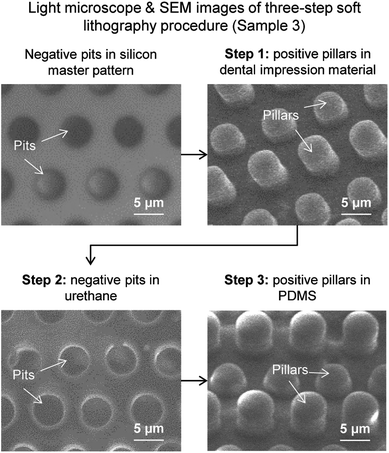
To characterize the geometric dimensions of the various samples, light microscope and SEM images provide a qualitative and quantitative comparison and understanding of the relevant parameters.Furthermore, images for each Sample 1–4 are shown in Fig. 10, with top views tilted at 45° and not tilted. Arrows on each image provide the flow direction for drag reduction. As shown, the features are accurately produced for each sample with geometric dimensions as indicated in Table 2. Dual-height pillars are evident in images of Sample 3 along with the dual height pillars/ribs of Sample 4. Each of the sample features appears smooth and with minimal defects from the soft-lithographic process. Information was gathered from SEM images at different magnifications to measure features of interest. Embossed sample 3 is shown in Fig. 11, with the top views tilted at 45° and not tilted. Upon careful comparison, the features have similar characteristics as with the PDMS molded Sample 3. There appears to be fine strands of presumably PMMA material on select pillars, which are believed to be remnants of the hot embossing procedure created during the de-molding step. As shown, the features are accurately produced for each sample with geometric dimensions as indicated in Table 2.
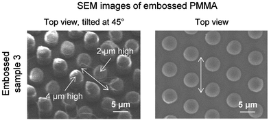 | ||
| Fig. 11 SEM images of Embossed sample 3 using the hot embossing procedure described in Fig. 5. Arrows indicate direction of anisotropic fluid movement. Shown is the top view tilted at 45° (left side) and with no tilt (right side) in order to highlight the feature heights. Comparing Sample 3 images from Fig. 10 using the soft-lithography procedure indicates successful hot embossing. | ||
4.2. Pressure drop measurements
To understand drag reduction of Samples 1–4 with water, oil, and air flow, a series of experiments are presented to study the various parameters. For each fluid, one plot shows the predicted flat channel line using eqn (1) to estimate pressure drop for a milled channel. In order to account for milled channel surface roughness, friction factor values estimated from the Moody chart were selected based on the roughness value of ε = 0.0025 mm. Additionally, each plot shows the milled channel control sample for comparison, and percentage pressure drops are calculated from the control sample. Included in Table 3 for Samples 1–4 and the rice leaf replica (nanostructured superhydrophobic coated urethane replica) are drag measurements and mechanisms for water, oil, and air experiments (where the “−” symbol indicates drag reduction, and the “+” symbol indicates drag increase).| Sample | Material | Low velocity flow (laminar for water, oil and air) | High velocity flow (turbulent for water and air; laminar for oil) | |||||
|---|---|---|---|---|---|---|---|---|
| Drag | Mechanism | Fig | Drag | Mechanism | Fig | |||
| a Adapted from ref. 26 and 27. | ||||||||
| Water | Sample 1 | PDMS | −7% | High contact angle | 12a | +1% | Vortices translating on pillars | 12b |
| Sample 2 | +4% | Flow impeded by tall pillars | +13% | Flow impeded by tall pillars, vortices translating on pillars | ||||
| Sample 3 | −15% | High contact angle, anisotropic flow | −12% | Anisotropic flow, vortices pinned | ||||
| Sample 4 | −9% | −5% | ||||||
| Embossed sample 3 | PMMA | −13% | Anisotropic flow | −23% | ||||
| Rice leaf replicaa | Urethane with super-hydrophobic coating | −26% | High contact angle, anisotropic flow | −26% | High contact angle, anisotropic flow, vortices pinned | |||
| Oil | Sample 1 | PDMS | −6% | Thin oil film effect | 13a | −3% | Thin oil film effect | 13b |
| Sample 2 | +11% | Flow impeded by tall pillars | +2% | Flow impeded by tall pillars | ||||
| Sample 3 | −1% | Anisotropic flow, thin oil film effect | −5% | Anisotropic flow, thin oil film effect | ||||
| Sample 4 | −2% | −2% | ||||||
| Embossed sample 3 | −5% | −6% | ||||||
| Rice leaf replicaa | Urethane with super-hydrophobic coating | −3% | −10% | |||||
| Air | Sample 1 | PDMS | +4% | Flow impeded by pillars | 14 | +5% | Flow impeded by pillars, vortices translating on pillars | 14 |
| Sample 2 | +5% | Flow impeded by tall pillars | +7% | Flow impeded by tall pillars, vortices translating on pillars | ||||
| Sample 3 | −3% | Anisotropic flow | −5% | Anisotropic flow, vortices pinned | ||||
| Sample 4 | −2% | −4% | ||||||
| Embossed sample 3 | PMMA | −10% | −12% | |||||
| Rice leaf replicaa | Urethane with super-hydrophobic coating | −17% | −20% | |||||
![[thin space (1/6-em)]](https://www.rsc.org/images/entities/char_2009.gif) 500) in Fig. 12b, with trend lines connected to the origin. Calculations use the values for mass density (ρ) equaling 1000 kg m−3 and kinematic viscosity (ν) equaling 1.034 × 10⁻⁶ m2 s−1.94
500) in Fig. 12b, with trend lines connected to the origin. Calculations use the values for mass density (ρ) equaling 1000 kg m−3 and kinematic viscosity (ν) equaling 1.034 × 10⁻⁶ m2 s−1.94
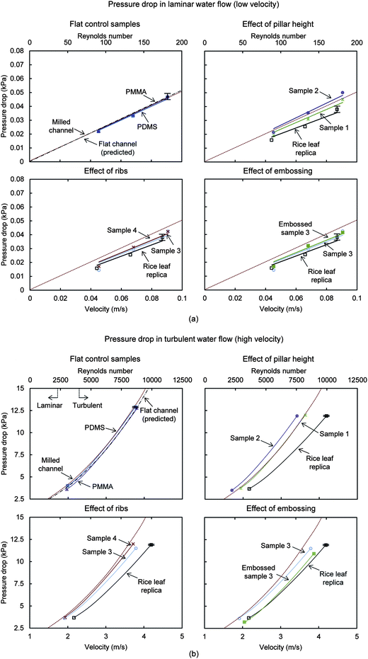 | ||
| Fig. 12 Water pressure drop with samples in (a) laminar flow using syringe pump and (b) turbulent flow using elevated container. For comparison, the predicted pressure drop for a flat rectangular closed channel is shown, calculated using the Darcy–Weisbach formula (eqn (1)). Also shown is the milled channel line, which serves as the reference sample when reporting pressure drop percentage values. Results are presented for rice leaf replica (with superhydrophobic nanostructured coating) (adapted from ref. 26), flat PDMS and PMMA, Samples 1–4, and Embossed sample 3. Higher pressure drop translates into higher drag; therefore lower pressure drop is desirable. The Embossed sample 3 yields the greatest drag reduction next to the rice leaf replica sample. Error bars show ±1 standard deviation, which is hardly visible in the plots. | ||
The top row shows the flat PDMS and PMMA control samples compared with the predicted pressure drop for a flat rectangular closed channel. Also shown is the effect of pillar height for Samples 1 and 2. The bottom row shows the effect of ribs and embossing for Samples 3 and 4, where a difference is detected at the higher flow velocities. At lower flow velocities, the flat control samples are nearly identical, and Sample 3 shows the greatest pressure drop reduction compared to Samples 1–4. When considering error bars, Embossed sample 3 shows similar pressure drop reduction as the rice leaf replica, which yields the greatest reduction in both laminar and turbulent flow. Results from the turbulent conditions indicate that Samples 1 and 2 increase the drag, and Samples 3 and 4 reduce the drag. The high contact angle, anisotropic flow, and pinning of vortices in turbulent flow with Samples 3 and 4 are believed to lower drag. Higher contact area between the turbulent vortices and the ribs in Sample 4 (as compared to Sample 3) are believed to lessen the drag reduction.
In laminar flow, Sample 3 and the rice leaf replica provide the greatest pressure drop reduction at 15% and 26%, respectively. In turbulent flow, Embossed sample 3 and the rice leaf replica provide the greatest pressure drop reduction at 23% and 26%, respectively.26 Sample 2 shows the greatest pressure drop increase at 13%, presumably due to the taller pillars impeding the fluid flow and vortices translating on the pillars. Furthermore in turbulent flow, Embossed sample 3 yields more pressure drop reduction than Sample 3, with values of 23% and 12%, respectively. Such values compare to other rectangular closed channel experiments conducted with micro-sized pillar samples, which yielded pressure drop reductions in laminar72 and turbulent flows.71
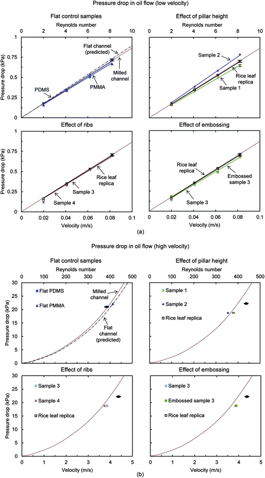 | ||
| Fig. 13 Oil pressure drop with samples in (a) laminar low velocity flow using syringe pump and (b) laminar high velocity flow using gear pump. For comparison, the predicted pressure drop for a flat rectangular closed channel is shown, calculated using the Darcy–Weisbach formula (eqn (1)). Also shown is the milled channel line, which serves as the reference sample when reporting pressure drop percentage values. Results are presented for rice leaf replica (with superoleophilic nanostructured coating) (adapted from ref. 27), flat PDMS and PMMA, Samples 1–4, and Embossed sample 3. Higher pressure drop translates into higher drag; therefore lower pressure drop is desirable. Embossed sample 3 yields the greatest drag reduction next to the rice leaf replica sample. Error bars show ±1 standard deviation, which is hardly visible in the plots. | ||
The top row shows the flat PDMS and PMMA control samples compared with the predicted pressure drop for a flat rectangular closed channel. Also shown is the effect of pillar height for Samples 1 and 2. The bottom row shows the effect of ribs and embossing for Samples 3 and 4, where a difference is detected at the higher flow velocities. At the low and high velocities, Samples 1, 3, 4, Embossed sample 3, and the rice leaf replica show drag reduction, which is believed due to anisotropic flow (all but Sample 1) and the thin film effect. In low velocity laminar flow, Embossed sample 3 and the rice leaf replica provide the greatest pressure drop reduction at 5% and 3%, respectively. In higher velocity laminar flow, Embossed sample 3 and the rice leaf replica provide the greatest pressure drop reduction at 6% and 10%, respectively.27 Sample 2 shows the greatest pressure drop increase at 11%, presumably due to the taller pillars impeding the fluid flow. The so-called thin film effect is believed to be present in all samples expect Sample 2.
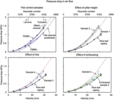 | ||
| Fig. 14 Air pressure drop with samples in laminar and turbulent flow using laboratory air supply. For comparison, the predicted pressure drop for a flat rectangular closed channel is shown, calculated using the Darcy–Weisbach formula (eqn (1)). Also shown is the milled channel line, which serves as the reference sample when reporting pressure drop percentage values. Results are presented for rice leaf replica (with nanostructured coating) (adapted from ref. 26), flat PDMS and PMMA, Samples 1–4, and Embossed sample 3. Higher pressure drop translates into higher drag; therefore lower pressure drop is desirable. Embossed sample 3 yields the greatest drag reduction next to the rice leaf replica sample. Error bars show ±1 standard deviation. | ||
With air, the achievable velocity range was higher as compared to the water or oil, and the higher Reynolds numbers show continued pressure drop reduction (until expected plateauing). At the low and high velocities, Samples 3 and 4, Embossed sample 3, and the rice leaf replica show pressure drop reduction, which is believed due to anisotropic flow and vortices pinned. In laminar flow, Embossed sample 3 and the rice leaf replica provide the greatest pressure drop reduction at 10% and 17%, respectively. In turbulent flow, Embossed sample 3 and the rice leaf replica provide the greatest pressure drop reduction at 12% and 20%, respectively.26 Sample 2 shows the greatest pressure drop increase at 7%, presumably due to the taller pillars impeding the fluid flow and vortices translating on the pillars. Furthermore, the rice leaf replica with the nanostructured superhydrophobic coating is reported to smooth-out the imperfections of the rice leaf replica, which is believed to further reduce pressure drop.26
4.3. Self-cleaning
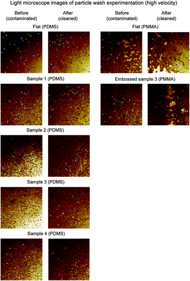
To understand the self-cleaning effectiveness of the various samples, a series of wash experiments were conducted. Samples were subjected to wash experimentation to determine self-cleaning efficiency. Presented for the high velocity wash experimentation are before and after images (dimensions are 180 × 180 μm) shown in Fig. 15 for flat PDMS and PMMA control samples, Samples 1–4, and the Embossed sample 3. These images were used with imaging software to quantify the percentage of particles removed. Tabulated data are shown in Fig. 16 for both the low and high velocity droplet wash experiments.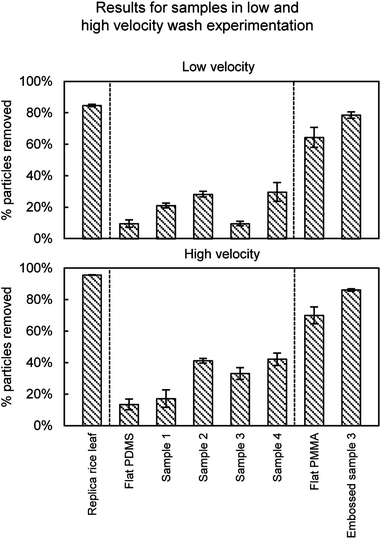 | ||
| Fig. 16 Self-cleaning results from particle wash experiments. Results are presented for rice leaf replica (with superhydrophobic nanostructured coating) (adapted from ref. 26), flat PDMS and PMMA, Samples 1–4, and Embossed sample 3. The rice leaf replica shows the greatest self-cleaning efficiency followed by the Embossed sample 3. Self-cleaning efficiency improves with high CA and low CAH. Error bars show ±1 standard deviation. | ||
As expected, the superhydrophobic rice leaf replica outperformed the other samples, and more particles were removed at higher versus lower velocities. Self-cleaning is demonstrated with rice leaf replica and Embossed sample 3 at 95% and 86% contaminant removal, respectively; as compared to uncoated samples at 85% and 70%, respectively (rice leaf replica data26). Interestingly, the Embossed sample 3 provides nearly the same self-cleaning ability as the rice leaf replica, even though Embossed sample 3 is not superhydrophobic. Nevertheless, high CA and low CAH is believed to amplify the self-cleaning abilities of the samples, as it is believed that the droplets are able to roll and collect the particles after impact. Furthermore, the nanostructure-coated samples are believed to exhibit lower adhesion forces, suggesting that the particles are easier to remove versus uncoated.
4.4. Wettability
To understand the role of apparent contact angle (CA) on drag and self-cleaning, a series of experiments were conducted with actual rice leaf, replica rice leaf, flat PDMS and PMMA control samples, Samples 1–4, and the Embossed sample 3. For completeness, included are results from experiments conducted with a superoleophobic coating.45 Droplet CA and CAH measurements were taken for water in air (solid–air–water), oil in air (solid–air–oil), and oil underwater (solid–water–oil). When high CA (>150°) is coupled low CAH (<10°), it is expected that liquid droplets will be easily repelled. Shown are contact angle results with images in Fig. 17 and tabulated values in Fig. 18. Contact angle measurements at the solid–air–oil interface are relevant for closed channel oil drag reduction; whereas measurements at the solid–water–oil interface are relevant for self-cleaning of underwater surfaces contacting oil, or vice versa.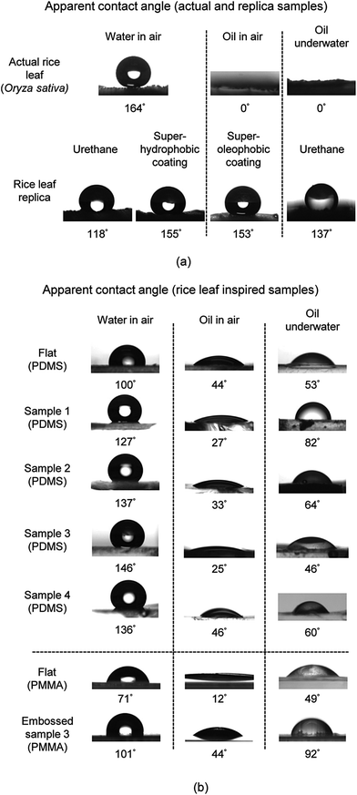 | ||
| Fig. 17 (a) Water droplet images indicating that actual rice leaves and the rice leaf replica (with superhydrophobic nanostructured coating) are superhydrophobic (adapted from ref. 26). Also shown are oil droplets in air and underwater, indicating that the superoleophobic coating on samples provide a high oil contact angle. (b) Montage of images of water droplets as well as oil in air and underwater for the flat PDMS and PMMA, Samples 1–4, and Embossed sample 3. Contact angle increases with roughness as indicated with water droplets but generally decreases with oil droplets in air and underwater. Sample 3 shows the highest water but the lowest oil contact angle in air. | ||
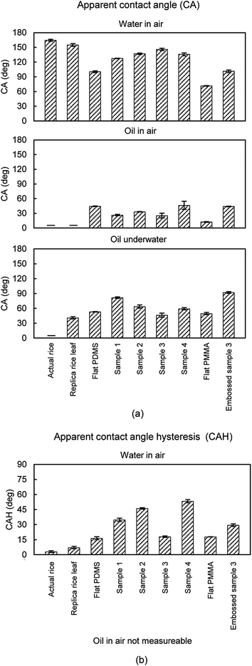 | ||
| Fig. 18 Results from (a) apparent contact angle (CA) and (b) contact angle hysteresis (CAH) experiments using actual and replica samples. Results are presented for actual rice leaf, rice leaf replica (with superhydrophobic nanostructured coating) (adapted from ref. 26), flat PDMS and PMMA, Samples 1–4, and Embossed sample 3. Shown are measurements of water droplets in air and oil droplets both in air and underwater. CAH for oil in air was not measureable, since the CA is too low. Self-cleaning efficiency improves with high CA and low CAH. Error bars show ±1 standard deviation. | ||
Actual rice leaf samples with higher contact angles are believed to exhibit Cassie-Baxter wetting where air pockets are trapped beneath the droplet to create superhydrophobicity, as shown in Fig. 17a.26 Conversely, Sample 1 shows a lower contact angle, presumably due to the Wenzel wetting when water penetrates between the individual asperities, as shown in Fig. 17b. Also as expected, the superhydrophobic rice leaf replica sample exhibits a higher water CA than the uncoated samples, showing the effectiveness of the superhydrophobic coating.26 Furthermore, PDMS Samples 1–4 exhibit hydrophobic contact angles with Sample 3 the highest at 146°. The PMMA samples exhibit lower CA, and for comparison Embossed sample 3 yields a CA of 101°. Since the surface energy of PDMS is lower than PMMA, this trend is expected. Tabulated CA is shown in Fig. 18a with CAH in Fig. 18b. As indicated, actual rice leaf provides the highest CA at 164° with the lowest CAH at 3°, indicating that water droplets are easily repelled. For comparison, maximum water contact angle of actual lotus leaves is 164°.95
Oil contact angle results are also presented. As shown at the solid–water–oil interfaces, actual rice leaf sample exhibits superoleophilicity. With actual rice leaf the lower surface tension oil spreads over the higher surface tension hierarchical rice leaf. The contact angles suggest oleophilic behavior except in the case of Embossed sample 3 underwater, which is shown to be oleophobic at 92°. As expected, the superhydrophobic coating of the rice leaf replica is oleophilic at the solid–water–oil interface, and the superoleophobic coating is superoleophobic at the solid–air–oil interface.45 Oil CAH cannot be determined due to the low oil contact angle in air.
When comparing the various samples, there is a noticeable difference where values vary significantly between actual and replica samples. This is reportedly due to the different mechanisms at work and how the sample materials and structures differ from the actual rice leaves. For instance, a low surface energy nanostructured coating was applied to rice leaf urethane replicas in order to mimic actual rice leaves; however the nanostructured morphology differs from actual rice leaves. The nanostructured coating consists of spherical particles in a low surface energy binder whereas actual rice leaves are covered by waxy nanobumps. Such differences may account for deviations in performance between replica and actual samples. The greatest difference is found with oil droplets, where for instance actual rice leaf is superoleophilic at the solid–water–oil interface whereas the uncoated replica rice leaf is oleophobic at the same interface. This is reported due to the lack of hierarchical structures on the replica that is present on the actual rice leaf. Once the superhydrophobic (superoleophilic) nanostructured coating is applied to the replica rice leaf, the oil contact angle nears the contact angle of actual rice leaf.27
As indicated, high CA alone does not automatically indicate drag reduction. It has been shown that superhydrophobic surfaces provide drag reduction,45,71,73 however we believe the surface must be relatively smooth for such benefit. For instance, Sample 2 shows a relatively high contact angle of 137° but also shows a drag increase in water, oil, and air. The tall pillars of Sample 2 are believed to impede fluid flow and the benefit from high contact angle is negated. For drag reduction, it is important to achieve high CA and low CAH with a relatively smooth surface such as the one employed with the rice leaf replica. In that sample, the nano-sized particles are dispersed in a low surface energy binder and deposited, which provide a very thin and relatively smooth surface conducive to drag reduction.
4.5. Mechanisms
With rice and butterfly wing effect surfaces, it is important to understand the mechanisms at work. Presented in Fig. 19 are models describing drag reducing and self-cleaning properties of the bioinspired Samples 1–4. It is believed that anisotropic flow present with Samples 3 and 4 helps to facilitate efficient fluid movement over the surface. This control minimizes movement of fluid molecules in the viscous sublayer and thus reduces the energy losses, which leads to lower drag. It is believed that the combination of anisotropic flow, liquid repellency, and vortices control are major contributors to drag reduction, self-cleaning, and potentially antifouling.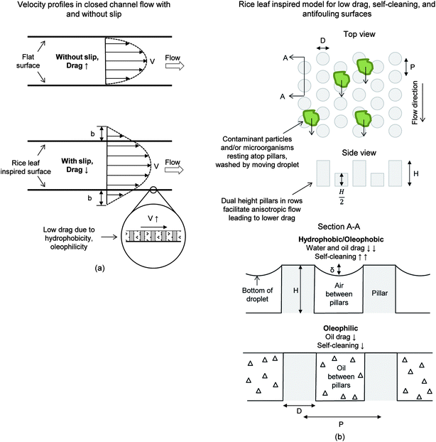 | ||
| Fig. 19 Rice leaf inspired models for low drag, self-cleaning, and antifouling surfaces. (a) Velocity profiles show that slip length (b) is believed to increase with the rice leaf inspired surfaces.27 This leads to lower drag, increased flow rate, and thus improved self-cleaning and antifouling. (b) Shown is the rice leaf inspired model using uniformly spaced micro-sized dual height pillars in a hexagonal array (adapted from ref. 26 and 27). This model was developed based on the rice and butterfly wing effect with dual height pillars promoting anisotropic flow. It is believed that drag reduction leading to self-cleaning may be achieved by either superhydrophobic/oleophobic or superoleophilic (thin film effect) surfaces. Furthermore, contaminant particles and/or microorganisms may be deterred from the surface due to the pillar spacing where such contaminates are unable to colonize the surface. | ||
Drag reduction is demonstrated in Fig. 19a, where hydrophobicity (water flow) and oleophilicity (oil flow) leads to slip length (b) increase and thus drag reduction. As previously mentioned, low contact angle in the case of oil flow may lead to drag reduction via the thin film effect. In oil flow, it is reported that replica rice leaf morphology may retain a thin oil film where oil fully penetrates the microstructures at the boundary layer to reduce drag,27 thus benefiting from the Wenzel regime.96 This drag reducing state is amplified with the superhydrophobic (superoleophilic) nanostructured coating on replicas or with the microstructured pattern of Sample 3 that further increases the oleophilicity. The thin-film effect is demonstrated in Fig. 19b with oil trapped and held stationary between the pillars. This is believed to have occurred with Samples 1, 3, 4 and Embossed sample 3. We also found that the Sample 4 combination of dual height pillars and ribs provide drag reduction and self-cleaning, however not as well as with dual height pillars. In turbulent flow, we believe the increased vortices to surface contact area found with ribs in Sample 4 (versus pillars in Sample 3) increases the shear stresses and thus drag.
Furthermore, the appropriate spacing of pillars shown in the top portion of Fig. 19b indicates that the microorganisms are unable to effectively colonize the surface, which is believed to promote antifouling. Microorganisms slightly larger than the gap spacing between features are less likely to colonize the surface, and we believe are more likely to be washed away in fluid flow. It is believed that the dual-height design of Sample 3 provides both drag reduction and self-cleaning, as shown in Fig. 19b. This surface can be successfully fabricated with hot embossing procedures, leading to anisotropic flow, thin film effect, and pinning of vortices – all of which reduces drag in water, oil, and air.
5. Conclusions
New bioinspired microstructured samples based on the rice and butterfly wing effect are shown to provide drag reduction and self-cleaning. We created these new samples using photolithography, soft-lithography, and hot-embossing procedures with inspiration from the relatively simple micropapillae morphology of rice leaves. The samples are believed to combine the desirable shark skin (anisotropic flow leading to low drag) and lotus leaf (superhydrophobic and self-cleaning) effects. The samples are also believed to potentially prevent the colonization of microorganisms leading to biofouling.Drag is reported with pressure drop measurements from sample lined rectangular closed channels (using water, oil and air in laminar and turbulent regimes). Additional experiments included self-cleaning, contact angle, and contact angle hysteresis with water and oil droplets – in both air and underwater. Measurements and images from light microscopy and SEM are included to provide qualitative and quantitative information on surface features and self-cleaning. We found that the samples with rice and butterfly wing effect characteristics show pressure drop reduction in water, oil, and air, increased contact angle, and improved self-cleaning efficiency. As previously reported, we believe the drag reducing thin-film effect is present in oil flow due to the higher viscosity oil, as compared to water or air.
The greatest drag reduction benefit is demonstrated in turbulent water flow; where the maximum pressure drop reduction occurs with the Embossed sample 3 and rice leaf replica at 23% and 26%, respectively. In laminar oil flow, we found a 6% pressure drop reduction using the Embossed sample 3 as compared to 10% with the rice leaf replica. Both samples are believed to benefit from the thin film effect. In turbulent air flow, we found a 12% pressure drop reduction using the Embossed sample 3 as compared to 20% with the rice leaf replica. The rice leaf replica is believed to benefit from an improved smoothness from the nanostructured coating. The greatest self-cleaning is shown with the lotus effect samples; where the maximum contaminant removal is shown with Embossed sample 3 and rice leaf replica at 86% and 95%.
A new low drag and self-cleaning surface model inspired by rice leaves has been created using a dual height micropattern of cylindrical pillars in a hexagonal array. We believe these surfaces can be further enhanced with appropriate nanostructure-coatings, depending on the fluid under investigation. We found that a combination of dual height pillars and ribs also provide pressure drop reduction and self-cleaning, however not as well as with dual height pillars. In turbulent flow, we believe the increased vortices to surface contact area found with ribs versus pillars increases the shear stresses and thus drag. Our bioinspired model is believed to reduce drag for many fluids, increase self-cleaning efficiency, and potentially promote antifouling. Furthermore, we found that the embossed surfaces provide pressure drop reduction and self-cleaning with similar performance as the rice leaf replica. These findings are promising for scaled-up production of new low-cost embossed films that may be applied to a variety of curved and flat surfaces.
The outlook of commercially viable rice and butterfly wing effect surfaces is promising for a variety of engineering applications; however a few areas could be further explored to provide greater insight into their optimization. These include more research to produce larger sized embossed sheets with an adhesive backing. Also, computer analysis would be helpful to verify and possibly discover new optimal geometric dimensions for a variety of fluids and flow conditions. Such analysis may include predicting drag and fluid interaction with pillars using ANSYS Fluent in order to optimize dimensions and orientations. Finally, bioassay experiments would be useful to quantify the microorganism antifouling effectiveness of our low drag and self-cleaning surfaces.
Acknowledgements
We would like to thank Mr Derek Ditmer of the Nanotech West facility (The Ohio State University Columbus, OH) for his assistance with soft lithography and hot embossing. We would also like to thank Mr Frank Zendejas of TRICR Corp. (San Francisco, CA) for his helpful discussion on silicon wafer fabrication. The financial support of this research was provided by a grant from the National Science Foundation, Arlington, VA (Grant # CMMI-1000108).References
-
M. W. Collins and C. A. Brebbia, Design and Nature II Comparing Design in Nature with Science and Engineering, WIT Press, Southampton, UK, 2004 Search PubMed
.
- B. Bhushan, Philos. Trans. R. Soc., A, 2009, 367, 1445–1486 CrossRef CAS PubMed
.
-
B. Bhushan, Springer Handbook of Nanotechnology, 3rd Edition, Springer, New York, 2010 Search PubMed
.
-
B. Bhushan, Biomimetics: Bioinspired Hierarchical-Structured Surfaces for Green Science and Technology, Springer-Verlag, Heidelberg, Germany, 2012 Search PubMed
.
-
Bulletproof Feathers How Science Uses Nature's Secrets to Design Cutting Edge Technology, ed. R. Allen, Ivy Press, London, 2010 Search PubMed
.
-
Bio-Inspired Innovation and National Security, ed. R. E. Armstrong, M. D. Drapeau, C. A. Loeb and J. J. Valdes, National Defense University Press, Washington, 2010 Search PubMed
.
-
Y. Bar-Cohen, Biomimetics: Nature Based Innovation, CRC Press, Boca Raton, Florida, 2011 Search PubMed
.
-
G. K. Batchelor, An Introduction to Fluid Dynamics, Cambridge University Press, Cambridge, 1970 Search PubMed
.
-
R. D. Blevins, Applied Fluid Dynamics Handbook, Van Nostrand-Reinhold, New York, 1984 Search PubMed
.
-
Standard Handbook for Aeronautical and Astronautical Engineers, ed. M. Davies, McGraw-Hill, New York, 2002 Search PubMed
.
-
F. White, Viscous Fluid Flow, McGraw Hill, New York, 3rd edn, 2006 Search PubMed
.
- W. Brostow, J. Ind. Eng. Chem., 2008, 14, 408–416 Search PubMed
.
- B. Bhushan, Y. C. Jung and K. Koch, Langmuir, 2009, 25, 3240–3248 CrossRef CAS PubMed
.
- B. Bhushan, Y. C. Jung and K. Koch, Philos. Trans. R. Soc., A, 2009, 367, 1631–1672 CrossRef CAS PubMed
.
- B. Bhushan and Y. C. Jung, Prog. Mater. Sci., 2011, 56, 1–108 CrossRef CAS
.
-
Fouling Science and Technology, ed. L. F. Melo, T. R. Bott and C. A. Bernardo, Kluwer Academic Publishers, Dordrecht, The Netherlands, 1988 Search PubMed
.
-
Recent Advances in Marine Biotechnology, ed. M. Fingerman, R. Nagabhushanam and M.F. Thompson, Science Publishers, Inc., Enfield, New Hampshire, 1999 Search PubMed
.
-
Industrial Biofouling Detection, Prevention and Control, ed. J. Walker, S. Surman and J. Jass, Wiley, New York, 2000 Search PubMed
.
-
A. I. Railkin, Marine Biofouling Colonization Processes and Defenses, CRC Press, Boca Raton, Florida, 2004 Search PubMed
.
-
Advances in Marine Antifouling Coatings and Technologies, ed. C. Hellio and D. Yebra, CRC Press, Boca Raton, Florida, 2009 Search PubMed
.
- G. D. Bixler and B. Bhushan, Philos. Trans. R. Soc., A, 2012, 370, 2381–2417 CrossRef CAS PubMed
.
- P. R. Viswanath, Prog. Aeronaut. Sci., 2002, 38, 571–600 CrossRef
.
-
A. Sareen, R. W. Deters, S. P. Henry and M. S. Selig, Paper # AIAA-2011-558, presented at 49th AIAA Aerospace Sciences Meeting, AIAA, Orlando, FL, New York, 2011 Search PubMed
.
-
Anon, Marine Fouling and its Prevention, Woods Hole Oceanographic Institute, US Naval Institute, Annapolis, US, 1952 Search PubMed
.
-
The Role of Biofilms in Device-Related Infections, ed. M. Shirtliff and J.G. Leid, Springer-Verlag, Berlin, 2009 Search PubMed
.
- G. D. Bixler and B. Bhushan, Soft Matter, 2012, 8, 11271–11284 RSC
.
- G. D. Bixler and B. Bhushan, Soft Matter, 2013, 9, 1620–1635 RSC
.
- E. D. Burger, W. R. Munk and H. A. Wahl, J. Pet. Technol., 1982, 34, 377–386 CrossRef CAS
.
-
J. L. Kennedy, Oil and gas pipeline fundamentals, PennWell Books, Tulsa, Oklahoma, 1993 Search PubMed
.
- Z. Deyuan, L. Yuehao, C. Huawei and J. Xinggang, Pipeline and Gas Journal, 2011, March, 59–60 Search PubMed
.
- R. Martínez-Palou, M. Mosqueira, B. Zapata-Rendón, E. Mar-Juárez, C. Bernal-Huicochea, J. Clavel-López and J. Aburto, J. Pet. Sci. Eng., 2011, 75, 274–282 CrossRef
.
- K. Koch and W. Barthlott, Philos. Trans. R. Soc., A, 2009, 367, 1487–1509 CrossRef CAS PubMed
.
- T.-S. Wong, S. H. Kang, S. K. Y. Tang, E. J. Smythe, B. D. Hatton, A. Grinthal and J. Aizenberg, Nature, 2011, 477, 443–447 CrossRef CAS PubMed
.
- S. Nishimoto and B. Bhushan, RSC Adv., 2013, 3, 671–690 RSC
.
- J. Hunt and B. Bhushan, J. Colloid Interface Sci., 2011, 363, 187–192 CrossRef CAS PubMed
.
- L. Cao, A. K. Jones, V. K. Sikka, J. Wu and D. Gao, Langmuir, 2009, 25, 12444–12448 CrossRef CAS PubMed
.
- A. J. Meuler, J. D. Smith, K. K. Varanasi, J. M. Mabry, G. H. McKinley and R. E. Cohen, ACS Appl. Mater. Interfaces, 2010, 2, 3100–3110 CAS
.
-
F. J. Marentic and T. L. Morris, US Pat. 5 133 516, 1992
.
- G. D. Bixler and B. Bhushan, Adv. Funct. Mater., 2013, 23, 4507–4528 CrossRef CAS
.
- K. Krieger, Science, 2004, 305, 636–637 CrossRef CAS PubMed
.
- M. L. Carman, T. G. Estes, A. W. Feinburg, J. F. Schumacher, W. Wilkerson, L. H. Wilson, M. E. Callow, J. A. Callow and A. B. Brennan, Biofouling, 2006, 22, 11–21 CrossRef CAS PubMed
.
- J. F. Schumacher, N. Aldred, M. E. Callow, J. A. Finlay, J. A. Callow, A. S. Clare and A. B. Brennan, Biofouling, 2007, 23, 307–317 CrossRef PubMed
.
-
A. J. Scardino, Advances in Marine Antifouling Coatings and Technologies, ed. C. Hellio and D. Yebra, CRC Press, Boca Raton, Florida, 2009, pp. 664–692 Search PubMed
.
-
A. B. Brennan, R. H. Baney, M. I. Carman, T. G. Estes, A. W. Feinberg, L. H. Wilson and J. F. Schumacher, US Pat., 7 650 848, 2010
.
- G. D. Bixler and B. Bhushan, Nanoscale, 2013, 5, 7685–7710 RSC
.
- L. Lin, Y. T. Cheng and C. J. Chiu, Microsyst Technol., 1998, 4, 113–116 CrossRef
.
-
L. Lin, C. J. Chiu, W. Bacher and M. Heckele, Paper # 0-7803-3596-1/96, presented at 7th International Symposium on Micro Machine and Human Science, IEEE, New York, 1996 Search PubMed
.
-
T. Velten, F. Bauerfeld, H. Schuck, S. Scherbaum, C. Landesberger and K. Bock, Paper # 978-2-35500-011-9, presented at DTIP, EDA Publishing, Seville, Spain, 2010 Search PubMed
.
- F. Klocke, B. Feldhaus and S. Mader, Prod. Eng. Res. Devel., 2007, 1, 233–237 CrossRef
.
- J. Narasimhan and I. Papautsky, J. Micromech. Microeng., 2004, 14, 96–103 CrossRef
.
- L. J. Kricka, P. Fortina, N. J. Panaro, P. Wilding, G. Alonso-Amigo and H. Becker, Lab Chip, 2002, 2, 1–4 RSC
.
- T. Mappes, M. Worgull, M. Heckele and J. Mohr, Microsyst. Technol., 2008, 14, 1721–1725 CrossRef CAS
.
-
S. Amaya, D. V. Dao and S. Sugiyama, Paper # 978-1-4244-5095-4/09, IEEE, New York, 2009 Search PubMed
.
- A. Mathur, S. S. Roy, M. Tweedie, S. Mukhopadhyay, S. K. Mitra and J. A. McLaughlin, Curr. Appl. Phys., 2009, 9, 1199–1202 CrossRef
.
-
J. Mizuno, T. Harada, T. Glinsner, M. Ishizuka, T. Edura, K. Tsutsui, H. Ishida, S. Shoji and Y. Wada, proceedings IEEE ICMENS, Banff, Canada, Aug 25–27, 26–29, 2004 Search PubMed
.
- N. Roos, T. Luxbacher, T. Glinsner, K. Pfeiffer, H. Schulz and H. C. Scheer, Proc. SPIE, 2001, 4343, 427–435 CrossRef CAS
.
- W. Barthlott and C. Neinhuis, Planta, 1997, 202, 1–8 CrossRef CAS
.
- C. Neinhuis and W. Barthlott, Ann. Bot., 1997, 79, 667–677 CrossRef
.
- A. Kesel and R. Liedert, Comp. Biochem. Physiol., Part A: Mol. Integr. Physiol., 2007, 146, S130 CrossRef
.
- E. Ralston and G. Swain, Bioinspiration Biomimetics, 2009, 4, 1–9 Search PubMed
.
-
D. W. Bechert, G. Hoppe and W. E. Reif, Paper # AIAA-85-0546, presented at AIAA Shear Flow Control Conference, AIAA, Boulder, CO New York, 1985 Search PubMed
.
- D. W. Bechert, M. Bruse, W. Hage, J. G. T. van der Hoeven and G. Hoppe, J. Fluid Mech., 1997, 338, 59–87 CrossRef
.
-
D. W. Bechert, M. Bruse, W. Hage and R. Meyer, Paper # AIAA-1997-1960, presented at AIAA 28th Fluid Dynamics Conference, AIAA, Snowmass Village, CO, New York, 1997 Search PubMed
.
- D. W. Bechert, M. Bruse and W. Hage, Exp. Fluids, 2000, 28, 403–412 CrossRef
.
- D. W. Bechert, M. Bruse, W. Hage and R. Meyer, Naturwissenschaften, 2000, 87, 157–171 CrossRef CAS PubMed
.
- S. J. Lee and S. H. Lee, Exp. Fluids, 2001, 30, 153–166 CrossRef
.
- B. Dean and B. Bhushan, Philos. Trans. R. Soc., A, 2010, 368, 4775–4806 CrossRef PubMed
.
- G. D. Bixler and B. Bhushan, J. Colloid Interface Sci., 2013, 393, 384–396 CrossRef CAS PubMed
.
- J. F. Schumacher, M. L. Carman, T. G. Estes, A. W. Feinberg, L. H. Wilson, M. E. Callow, J. A. Callow, J. A. Finlay and A. B. Brennan, Biofouling, 2007, 23, 55–62 CrossRef CAS PubMed
.
-
M. Nosonovsky and B. Bhushan, Multiscale Dissipative Mechanisms and Hierarchical Surfaces, Springer, New York, 2008 Search PubMed
.
- Y. C. Jung and B. Bhushan, J. Phys.: Condens. Matter, 2010, 22, 1–9 Search PubMed
.
- J. Ou, B. Perot and J. P. Rothstein, Phys. Fluids, 2004, 16, 4635–4643 CrossRef CAS
.
- R. J. Daniello, N. E. Waterhouse and J. P. Rothstein, Phys. Fluids, 2009, 21, 085103 CrossRef
.
- M. B. Martell, J. B. Perot and J. P. Rothstein, J. Fluid Mech., 2009, 620, 31–41 CrossRef
.
- M. B. Martell, J. P. Rothstein and J. B. Perot, Phys. Fluids, 2010, 22, 065102 CrossRef
.
- T. Wagner, C. Neinhuis and W. Barthlott, Acta Zool., 1996, 77, 213–225 CrossRef
.
- J. C. O'Toole, R. T. Cruz and J. N. Seiber, Physiol. Plant., 1979, 47, 239–244 CrossRef
.
- L. Feng, S. Li, Y. Li, H. Li, L. Zhang, J. Zhai, Y. Song, B. Liu, L. Jiang and D. Zhu, Adv. Mater., 2002, 14, 1857–1860 CrossRef CAS
.
- T. Sun, L. Feng, X. Gao and L. Jiang, Acc. Chem. Res., 2005, 38, 644–652 CrossRef CAS PubMed
.
- Z. Guo and W. Liu, Plant Science, 2007, 172, 1103–1112 CrossRef CAS
.
- K. Liu and L. Jiang, Nano Today, 2011, 6, 155–175 CrossRef CAS
.
- Y. Zheng, X. Gao and L. Jiang, Soft Matter, 2007, 3, 178–182 RSC
.
- P. P. Goodwyn, Y. Maezono, N. Hosoda and K. Fujisaki, Naturwissenschaften, 2009, 96, 781–787 CrossRef PubMed
.
- O. Sato, S. Kubo and Z. Z. Gu, Acc. Chem. Res., 2009, 42, 1–10 CrossRef CAS PubMed
.
-
S. Vajda, Fibonacci & Lucas numbers, and the golden section: theory and applications, Halsted Press, New York, 1989 Search PubMed
.
-
M. Livio, The golden ratio: the story of phi, the world's most astonishing number, Broadway Books, New York, 2002 Search PubMed
.
-
A. S. Posamentier and I. Lehmann, The fabulous Fibonacci numbers, Prometheus Books, New York, 2007 Search PubMed
.
- D. Ebert and B. Bhushan, J. Colloid Interface Sci., 2012, 384, 182–188 CrossRef CAS PubMed
.
- D. Ebert and B. Bhushan, Langmuir, 2012, 28, 11391–11399 CrossRef CAS PubMed
.
- L. Gitlin, P. Schulze and D. Belder, Lab Chip, 2009, 9, 3000–3002 RSC
.
- J. Foncy, J. C. Cau, C. Bartual-Murgui, J. M. Francois, E. Trevisiol and C. Severac, Microelectron. Eng., 2013, 110, 183–187 CrossRef CAS
.
- D. W. Bechert, G. Hoppe, J. G. T. van der Hoeven and R. Makris, Exp. Fluids, 1992, 12, 251–260 CrossRef CAS
.
-
R. W. Fox and A. T. McDonald, Introduction to Fluid Mechanics, Wiley, New York, 1998 Search PubMed
.
-
CRC Handbook of Chemistry and Physics, 90th Edition, ed. D. R. Lide, CRC Press, Boca Raton, Florida, 2009 Search PubMed
.
- K. Koch, B. Bhushan, Y. C. Jung and W. Barthlott, Soft Matter, 2009, 5, 1386–1393 RSC
.
- R. N. Wenzel, Ind. Eng. Chem., 1936, 28, 988–994 CrossRef CAS
.
| This journal is © The Royal Society of Chemistry 2014 |

