 Open Access Article
 This Open Access Article is licensed under a Creative Commons Attribution-Non Commercial 3.0 Unported Licence
Simulation of the shape and size of casein micelles in a film state
Ronald
Gebhardt
*a and
Ulrich
Kulozik
b
aTechnische Universität München, Chair for Food Process Engineering and Dairy Technology, Weihenstephaner Berg 1, 85354 Freising-Weihenstephan, Germany. E-mail: ronald.gebhardt@tum.de
bResearch Centre for Nutrition and Food Science (ZIEL) – Section Technology, Technische Universität München, Germany
First published on 21st January 2014
Abstract
Size fractionated casein micelles (CMs) form homogeneous films in which they are densely packed. The lateral size of CMs in films can be well resolved by surface-sensitive methods, but the estimation of their heights is still a challenge. We show that height information can be obtained from scattering patterns of GISAXS experiments on highly ordered casein films. We use an elastic scattering approach within the distorted wave Born approximation (DWBA) to simulate for the first time the two-dimensional intensity distribution of a GISAXS experiment of the CM near their critical angle. The model which fits the GISAXS data best considers an ellipsoidal form factor for the CM and an arrangement on a hexagonal lattice. Our results indicate that during film formation the spherical solution structure of CMs becomes compressed in the direction perpendicular to the film surface. In the film state, the micelles assume an oblate ellipsoidal shape with an aspect ratio of 1.9. Hence, their surface and contact area to the surrounding increases. As a result, the density of κ-casein on the micellar surface decreases, which could influence the functional properties of coatings and films.
Introduction
CMs are association colloids composed of four different proteins (αS1-, αS1-, β- and κ-caseins) and colloidal calcium phosphate.1 The internal architecture of the CM can be illustrated using the nanocluster model, which is based on a number of small-angle neutron scattering experiments.2,3 According to this model, calcium phosphate nanoclusters are dispersed in a homogeneous matrix of caseins which is held together by weak, cooperatively acting interactions.3 Most of the knowledge concerning the surface structure of CMs has been obtained from functional and surface-sensitive experiments. It has been shown by electron and atomic force microscopy that CMs possess a heterogeneous raspberry-like surface.4 A surface layer of κ-casein protrudes approx. 10 nm into the surrounded media and provides colloidal stability.5 The sizes of CMs are log-normally distributed between 50–400 nm.6 Sharply distributed CMs can be separated from their original size distribution by differential ultracentrifugation.7,8 Once sharply distributed in size, CMs pack densely and highly ordered and form films with smooth surfaces.9,10 Structural characterization of CMs in films demands surface-sensitive methods. GISAXS, atomic force and electron microscopy have been used to explore structural changes in the mean dimension of CMs, in their internal structure and surface. None of these techniques could so far provide detailed information about the three-dimensional structure of surface-near CMs under native conditions. Indeed, the shape and size of CMs determine the surface area and thus the kind and strength of interactions with the surrounding. This plays an important role in the functional properties of coatings, films, glues and paints based on CMs as a raw material.In this paper we show that precise information about the 3D-structure of CMs in films can be obtained from GISAXS measurements, provided all micelles are equally sized and regularly arranged. We describe for the first time how the structural information can be extracted by modeling and simulation of a GISAXS pattern. The analysis is based on the distorted wave Born approximation (DWBA) which takes the multiple scattering events during the scattering process on the surface into account.
Experimental
Theoretical background
Fig. 1A illustrates the interaction of X-rays with matter on a smooth solid–air surface. Generally, the incoming wave is both reflected and refracted on an interface. The wave vectors ki, kf and kt point in the direction of propagation of the corresponding waves. Total reflection occurs when the angle of incidence is below a critical value because in the X-ray range matter has a smaller refractive index (n) than air. Fig. 1B and 2 illustrate scattering processes on a CM deposited on a smooth solid–air surface under a grazing incidence angle. Within the distorted-wave Born approximation four scattering processes are considered where the incoming wave is either (1) only scattered or (2) first reflected and then scattered or (3) first scattered and then reflected or (4) first reflected, then scattered and reflected again.11 | ||
| Fig. 1 (A) Scattering geometry: X-rays of wave vector ki are both reflected (kf) and refracted (kt) at a smooth solid–air surface; (B) Specific wave vector transfers for four scattering events which are considered within the DWBA. | ||
 | ||
| Fig. 2 Surface-near structures of the sample are mapped in inverse space on a CCD detector installed at a fixed distance behind the sample. The exact alignment of the sample plane to the incoming X-ray beam is ensured by translation along three directions and rotation around two axes. | ||
Simulation
For simulations we used IsGISAXS.12 The program uses an elastic scattering approach to compute the scattering cross-section, defined by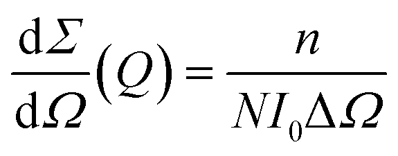 | (1) |
 | (2) |
Simulations were performed within the local monodisperse approximation (LMA). The LMA replaces the scattering power of each particle by the mean value of the assumed size distribution according to:
 | (3) |
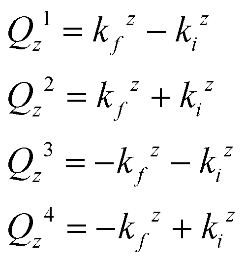
Because of the assumed four scattering events the form factor F depends on Qy and Qzn:
| F(Q||, Qzn) = F(Q||, Qz1) + Rf(αi)F(Q||, Qz2) + Rf(αf)F(Q||, Qz3) + Rf(αi)Rf(αf)F(Q||, Qz4) | (4) |
 | (5) |
The interference function S(Q) is the Fourier transform of the hexagonal island–island correlation function.
Sample preparation
Sequential sedimentation with a Beckmann centrifuge was used to extract a size-fraction of CMs from raw skimmed milk. After centrifugation, the pellet was washed four times and subsequently dissolved in a buffer containing 50 mM Tris–HCl and 50 mM CaCl2, pH 7.5.13 The concentration of the remaining whey proteins was close to zero as proved by high-performance liquid chromatography. The isolate fraction of CMs had a sharp size distribution as indicated by an almost mono-exponential field-correlation function resulting from dynamic light scattering measurements with a Zeta-sizer Nano-S (Malvern, UK) in backscattering geometry (173°). Despite size-fractionation, only a lower limit of dH = 150 nm for the mean hydrodynamic size can be provided from the measurements because CMs are still size-distributed and show angle-depend light scattering. The as-prepared CMs were deposited on Si-wafers and cast at room temperature. After film formation, the sample was immediately examined by GISAXS.Surface-sensitive experiments on casein films
Results and discussion
In Fig. 3A the GISAXS pattern of a highly ordered casein film is shown as measured in a scattering experiment. The two-dimensional intensity distribution is plotted on a logarithmic scale and expressed as a function of the out-of plane angle ψ and the exit angle αf. The pattern contains intensity in a central rod at ψ = 0°, which is caused by the surfaces roughness. The shadow of the used beam-stop 2 is visible at an exit angle of αf = 0.39°. Most of the scattered intensity is detected at low exit angles between αf = 0° and 0.1°. In that angular range, an interference pattern consisting of pronounced peaks is visible. | ||
| Fig. 3 (A) Two-dimensional intensity distribution of a GISAXS experiment on a highly ordered CM in a film prepared on a silicon wafer. The angles αf1, αf2 and ψ are indicated at which we extract the horizontal and vertical cuts for a detailed simulation. (B) Dimensions of the sample surface over which the GISAXS experiment averages are compared to those of a typical AFM image. | ||
Fig. 3B gives an impression about the area over which the GISAXS experiment averaged compared to the dimension of a single CM mapped by AFM. The interference pattern in Fig. 3A indicates that CMs are arranged in an ordered lattice structure over an area (3400 × 32 μm2) which is by a factor of approx. 1.7 × 10⁶ larger than the lateral dimensions of a single CM (0.25 × 0.25 μm2).
For a detailed analysis of the GISAXS pattern in Fig. 3A we built a model which matches the features of the two-dimensional intensity distribution. First, we extracted two horizontal cuts at the exit angles of αf1 = 0.016° and αf2 = 0.048° and one vertical cross-section at ψ = 0.04° from the GISAXS pattern (Fig. 3A). The one-dimensional scattering functions are plotted as a function of the calculated components of the momentum transfer vector, Q (eqn (2)) in Fig. 4. In the next step, we used IsGISAXS to establish a suitable model which accounts for both the structure of CM in densely packed films (shape, size, and structural arrangements) and the complex scattering process on particles cast on a smooth solid support. The only model which was able to fit the data well consists of an ellipsoidal form factor with log-normally distributed sizes for the vertical and lateral semi-axes and an interference function which accounts for a paracrystal with a hexagonal symmetry. The form factor defines the size and shape of a single CM while the interference function describes the structural arrangement of an ensemble of CMs. The model was simultaneously fitted to all one-dimensional cross-sections of the two-dimensional intensity distribution using the Levenberg–Marquardt method and a chi-square test to control the quality of the fit.
 | ||
| Fig. 4 Horizontal (A) and vertical (B) cross-sections of the GISAXS pattern at αf1 = 0.016°, αf2 = 0.048° and ψ = 0.04° together with the best simultaneous fit of the most appropriate model. | ||
The solid lines in Fig. 4 represent the model fit to the experimental data expressed as symbols. The fit matches the data well. Despite deviations in the background, all major interference peaks have been identified by the fit. The obtained values for the model parameters are shown in Table 1.
| Parameter | Fit | Sim 1 | Sim 2 |
|---|---|---|---|
| R (nm) | 125 | 105 | 155 |
| h (nm) | 132 | 223 | 85 |
| D (nm) | 250 | 250 | 250 |
For the CM embedded in the film we obtained a lateral dimension, R = 125 nm and the height, h = 132 nm from the fit. Furthermore, the nearest neighbor distance was estimated to be D = 250 nm. Hence, according to our model, the CMs assume an oblate ellipsoidal shape and are surrounded by six nearest neighbors arranged on a hexagonal lattice. We used the values from the fit to simulate the GISAXS pattern. We focused on a small angular part of the scattering pattern (where most of the scattering features are contained) in order to ensure reasonable calculation times together with sufficient resolution of the simulated pattern. Fig. 5A shows the used section of the scattering pattern (see Fig. 3A) in an enlarged view. We performed the simulation within the distorted wave Born approximation (DWBA) as the considered angular part of the GISAXS is below the critical angle of the material of the probed surface. As explained above, the DWBA considers four scattering processes because besides single X-ray scattering on the micelles, the X-rays can also be reflected before or/and afterwards on the surface of the silicon wafer. A combined form factor has to be taken into account (eqn (4)) which sums up the contributions from the four scattering events. In detail, the four form factor contributions are calculated as a function of the specific wave vector transfers (eqn (5)) and weighted by the reflectivities for the incoming and outcoming waves. To describe the structural arrangement of CMs we used the interference function for a paracrystal of hexagonal symmetry. The choice is based on AFM measurements showing that size-fractionated CMs pack densely and tend to order hexagonally.10
 | ||
| Fig. 5 Section of the experimental GISAXS pattern of size-fractionated CMs prepared on top of a silicon wafer (A) and the corresponding simulation (B). The intensity is represented on a logarithmic gray scale. | ||
To model the interplay between the form factor and the interference function we used the local monodisperse approximation (LMA). The LMA assumes a mean value for the scattering weight of particles distributed in size (eqn (3)) so that the intensities are the incoherent sum of the scattering intensities of monodisperse subsystems weighted by the size-shape probabilities.12
Fig. 5B shows the simulated scattered intensity which can be directly compared to the experimental data in Fig. 5A. The comparison shows that the simulated intensity matches fairly well with the peaks of the experimental GISAXS pattern in both vertical and horizontal dimensions. Furthermore, experimental and simulated intensities expressed on a gray scale are in good accordance. Differences in the width of the central rod are due to limitations of the experiment. The surface roughness of the films and the instrumental resolution function generally influence the intensity distribution in the angular range around ψ = 0°.
We performed two further simulations with assumed values in order to show the influence of the dimensions of an ellipsoid on the positions of the correlation peaks in the scattering functions.
The parameter values for the simulations with the assumed prolate ellipsoid (Sim 1) and oblate ellipsoid (Sim 2) are summarized in Table 1. Horizontal and vertical cross-sections of the simulated GISAXS pattern are plotted in Fig. 6 as lines together with the experimental data (open circles).
 | ||
| Fig. 6 Data from (A) horizontal (αf = 0.016°) and (B) vertical (ψ = 0.04°) cross-sections of the GISAXS pattern (open circles) together with two simulations (lines) with assumed values from Table 1. | ||
The intensity peaks of the experimental GISAXS data are marked by vertical dashed lines and numbered from 1–4. The first simulation (Sim 1) concerns a prolate ellipsoid with a reduced lateral size and a larger height as compared to the dimension of the ellipsoid from the fit. The scattering function of Sim 1 in Fig. 6A shows no correlation with the second intensity peak. As a result of the smaller lateral size the peak is shifted towards larger Qy-values in the inverse space. In contrast, the larger height of the prolate leads to a shift towards smaller Qz-values in the vertical cross-section (Fig. 6B). The same tendency but in the opposite direction can be observed for the oblate ellipsoid (Sim 2). The corresponding scattering functions are indicated by dotted lines in Fig. 6. Here, the larger lateral dimension leads to a shift towards smaller Qy-values and the smaller height to a shift towards larger Qz-values. The comparison of the experimental data with simulation shows how sensitive the peak positions in the scattering functions react on changes in the dimensions of the ellipsoids.
It has been shown that soft polymers deform during thin film formation. First there is an initial concentration step of the particles in closely packed arrays. Then, stress due to both interfacial tension and external forces occurs in the still wet film leading to the compression of the particles in the normal direction.15 During drying, CMs deform and assume an ellipsoidal shape according to the results of our GISAXS simulation. The transition from a sphere into an oblate ellipsoid is in accordance with a drying-induced compression normal to the film surface. As a result of the deformation an ellipsoid with an aspect ratio of 1.9 is formed. Compared with the surface of a sphere of an equal volume, this corresponds to an increase in the surface area by a factor of 8%. The expansion of the micellar surface directly affects the density of κ-casein in the surface. The κ-surface layer, which provides steric stabilization under undisturbed conditions, loses effectiveness. For that reason, it can be assumed that interaction between the CMs and their surrounding changes and, as a consequence, new functional properties of CM on surfaces and at interfaces might occur.
Conclusions
GISAXS was used to study the surface-structure of CMs in highly ordered films. In contrast to surface-sensitive methods such as AFM and EM, GISAXS provides precise height information of the film forming particles. This is especially interesting for particles showing deformation when subjected to shearing forces. However, GISAXS measurements on highly ordered CMs are needed to obtain scattering patterns from which precise height information can be extracted. Highly ordered films can be produced by a size fractionation (centrifugation) of CMs prior to the drying process. The corresponding GISAXS signal contains interference peaks with scattering contributions from single particle scattering (form factor) and the formed hexagonal lattice (structure factor) of the CM. From the best model fit and simulations we found that the spherical solution structure of the CM becomes compressed during the film formation process and assumes an oblate ellipsoidal shape. The shape changes lead to an increase in the surface area of the CM. As a result, the density of κ-caseins on the surface of CMs decreases which influences the interaction between CMs and their surroundings. This new aspect should be addressed in future basic and applied studies on CMs in surfaces and interfaces. Furthermore, GISAXS experiments depending on different size-fractions and wafer treatments could be performed in order to investigate the influence of the particle size and the underlying substrate on our findings.Acknowledgements
We thank T. Steinhauer, W. Holzmüller, P. Meyer, Q. Zhong (TUM, Physics Department) and V. Körstgens (TUM, Physics Department) for their help during the experiments and P. Müller-Buschbaum (TUM, Physics Department) for helpful discussions and providing resources. J. Perlich (HasyLab/Desy) is acknowledged for setting up the beamline. This work is supported by the DFG-grant (DFG GE 2375/1-1) and the long-term project II-20100114 from HasyLab/Desy.Notes and references
- C. G. de Kruif, Int. Dairy J., 1999, 9, 183 CrossRef CAS.
- C. Holt, et al. , Colloids Surf., A, 2003, 213, 275 CrossRef CAS.
- C. G. de Kruif, et al. , Adv. Colloid Interface Sci., 2012, 171–172, 36 CrossRef CAS PubMed.
- M. Ouanezar, et al. , Langmuir, 2012, 28, 4915 CrossRef CAS PubMed.
- C. G. de Kruif and E. B. Zhulina, Colloids Surf., A, 1996, 117, 151 CrossRef CAS.
- P. F. Fox and A. Brodkorb, Int. Dairy J., 2008, 18, 677 CrossRef CAS PubMed.
- S. Marchin, et al. , J. Chem. Phys., 2007, 126, 45101 CrossRef PubMed.
- M. Heinrich and U. Kulozik, Int. Dairy J., 2011, 21, 664 CrossRef CAS PubMed.
- R. Gebhardt, C. Vendrely and U. Kulozik, J. Phys.: Condens. Matter, 2011, 23, 444201 CrossRef CAS PubMed.
- R. Gebhardt, et al. , Colloids Surf., B, 2011, 88, 240 CrossRef CAS PubMed.
- R. Markus, et al. , J. Appl. Phys., 1999, 86, 6763 CrossRef PubMed.
- R. Lazzari, J. Appl. Crystallogr., 2002, 35, 406 CrossRef CAS.
- R. Gebhardt, J. Appl. Crystallogr., 2014, 47, 29–34 CAS.
- J. Perlich, et al. , Rev. Sci. Instrum., 2010, 81, 105105 CrossRef CAS PubMed.
- M. S. Tirumkudulu and W. B. Russel, Langmuir, 2004, 20, 2947 CrossRef CAS.
| This journal is © The Royal Society of Chemistry 2014 |