Two stories from the ISACS 12 conference: solar-fuel devices and catalyst identification
Zhuangqun
Huang
,
Chengxiang
Xiang
,
Hans-Joachim
Lewerenz
and
Nathan S.
Lewis
*
Joint Center for Artificial Photosynthesis, California Institute of Technology, 1200 E. California Blvd, Pasadena, CA 91125, USA. E-mail: nslewis@caltech.edu
ISACS 12 focused heavily on the development of economic, sustainable, and scalable ways to produce fuels from sunlight, H2O and CO2. Hence, terms such as “solar fuels”, “artificial leaf”, “CO2 reduction”, and “water splitting” were frequently used by conferees. Because almost all of the talks in the “molecular catalysis” theme focused on catalysts for the solar-driven production of fuels (and CO2 reduction in particular), half of the talks at ISACS 12 were concerned with solar fuels.
Concerted national and international efforts may be required to produce breakthroughs in the science of solar fuels, and therefore regional and global education and research collaborations have critical roles to play in support of these efforts. The invited speakers at ISACS 12 were drawn from top solar-fuel programs. Prof. Harry Gray, director of the NSF Center for Chemical Innovation in Solar Fuels (CCI Solar), USA, introduced his solar army (http://www.thesolararmy.org/) to the ISACS 12 audience and emphasized the importance of education during the BBC program. Prof. Gray underscored that kids represent not only future researchers, but also future policy makers, and he is actively recruiting and encouraging young kids to start tackling the energy problem. Prof. Ib Chorkendorff, director of the Catalysis Initiative for Sustainable Energy (CASE) in Denmark and Prof. Shunichi Fukuzumi, Director of the Advanced Carbon Technology Research and Development in Japan, were also invited speakers. Dr Stephanie Pendlebury introduced the Solar Fuels Network, a UK-based organization directed by Prof. James Durrant, which has been established to develop “an effective community of researchers from both academia and industry who investigate routes to solar-driven fuels synthesis” (http://www.solarfuelsnetwork.com/).
In this article, we relate two stories of solar fuels research from ISACS 12: design of a solar-fuel device and differentiation of an active molecular catalyst.
1. What is your favorite design for a solar-fuel generator?
As shown in Schemes (A)–(D) in Fig. 1, four main designs are currently popular for guiding the construction of solar fuel-generating devices. These four designs differ in terms of their component integration, maturity, technological development, and fundamental understanding.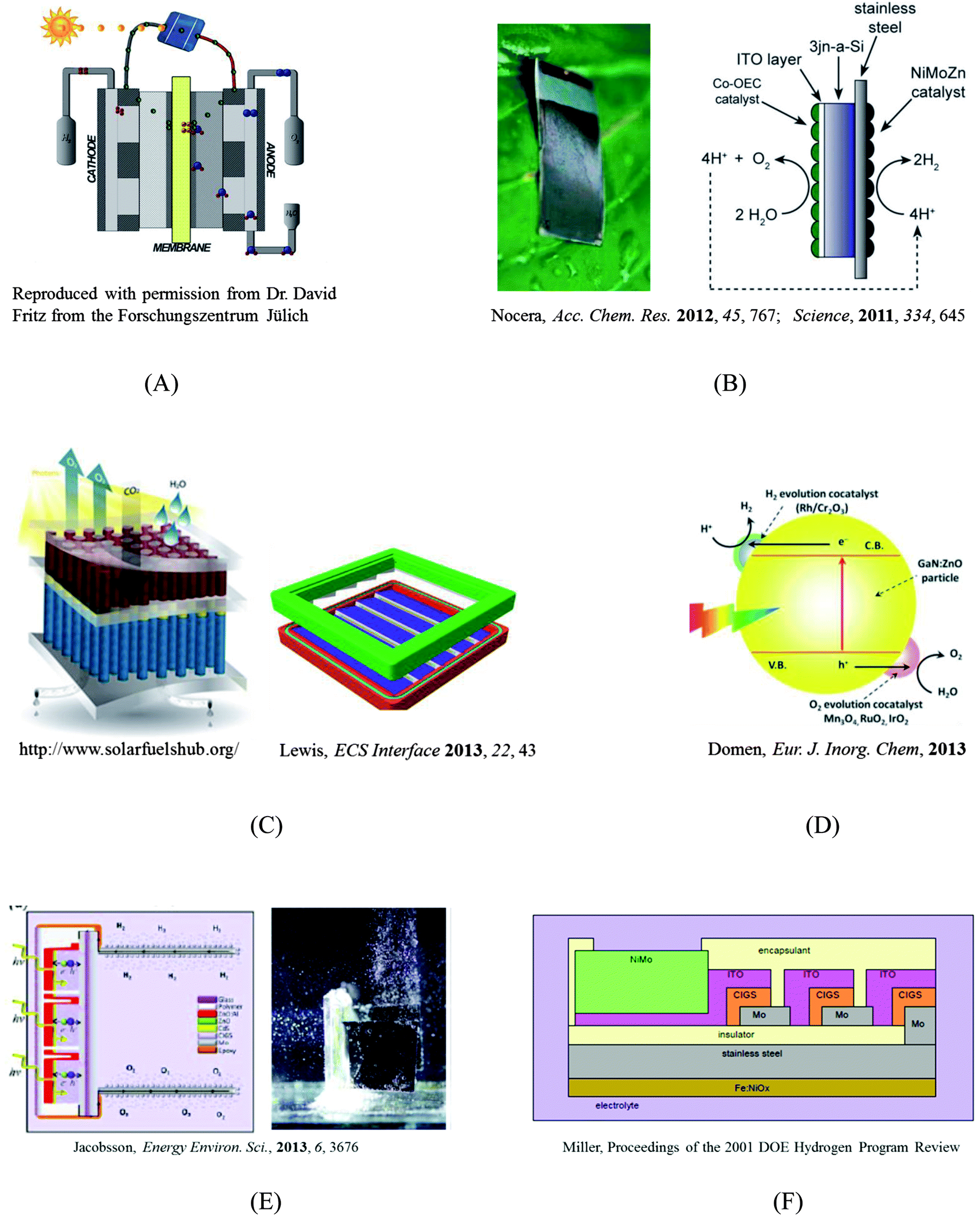 | ||
| Fig. 1 Selected designs of solar-fuel devices. (A) A photovoltaic-electrolyzer design; (B) A monolithic “artificial leaf”;1,2 (C) A highly integrated design and a preliminary prototype that includes a membrane that can separate the products of electrolysis while maintaining high ionic conductivity;3 (D) A colloidal system;4 (E) and (F) Two (CIGS)3 photovoltaic-electrolyzer designs.5,6 | ||
Scheme A is a series connection of two established technologies: a photovoltaic (PV) power supply and an electrolysis cell. The primary strength of this design is that the PV component and the electrolysis component can be independently engineered and optimized. However, the high costs of the PV and electrolyzer mean that hydrogen produced from this design may cost significantly more than hydrogen produced by steam reforming, a method that relies on fossil fuels (i.e., CH4 + H2O ⇌ CO + 3H2). Moreover, this design requires a “buried” junction in the stand-alone PV, preventing the use of a semiconductor–electrolyte junction, in which a single light-absorbing material (e.g., WO3, Fe2O3) serves as a photocathode or anode in contact with the electrolyte solution. Although the prices of PVs have reached historical lows in the past few years, in part due to economies of scale, the efficiencies of PVs and electrolyzers have only been marginally improved over the same time-frame. Unless a disruptive technological breakthrough that greatly enhances the system efficiency takes place, the cost of a serially connected system is unlikely to rival that of steam reforming technologies in the near future.
The concept of a monolithic, or highly integrated, solar fuel generation system has gained popularity with researchers. Detailed comparisons between an integrated photoelectrolysis device and a serially connected PV–electrolyzer system, for different combinations of photoabsorbers and cell-operation environments (irradiation and temperature), have shown that the integrated system can leverage enhanced kinetics and mass transport at elevated temperatures and outperform a PV–electrolyzer device on an annual hydrogen yield basis.7,8
Prof. Daniel Nocera from MIT has been a recent, vocal proponent of the “artificial leaf” design, shown in Scheme B of Fig. 1, as originally proposed and implemented by Ayers9 and then by Miller and Rocheleau.10 The artificial leaf is a silicon solar cell with water-splitting catalysts directly bonded to both of its sides. This design basically replaces the thylakoid membrane scaffold with a PV cell, and is arguably the limiting case for PV–electrolyzer systems, where the wires are the contacts between the PV and catalysts. In this design, extra heat from sunlight can be used to reduce the thermodynamic barrier for fuel generation and device optimization can be performed at the component level without much concern about material integration beyond the series resistance at the interfaces.11 However, this device lacks a means for separating the products of electrolysis, and covering the PV with catalysts means that some light will be blocked. Both Schemes A and B follow the same fundamental principle for fuel generation, and the solar-to-hydrogen (STH) energy-conversion efficiencies for these designs have been evaluated using a theoretical model that generally assumes a serial combination of catalyst kinetics (i.e., the Butler–Volmer equation) and photodiode response (i.e., the Shockley diode equation).8,12
Scheme C in Fig. 1 shows a highly integrated design as well as its preliminary prototype. This design includes a membrane that can separate the products of electrolysis while maintaining high ionic conductivity. The tandem structure allows the use of semiconductor–liquid junctions and provides more opportunities for device optimization.13 However, the fundamentals that govern the interfacial charge-transfer dynamics at semiconductor–liquid junctions remain poorly understood. Parameters include catalyst selection, interfacial chemical composition, mixed-barrier-height interfacial energetics, in situ H2/O2 alloying, and light collection.14 Building such a device requires scientific and technological developments over a wide range of scales, from discovery of catalysts (molecular-scale) to construction of a fully integrated prototype (macro-scale). The efforts of America's largest research program dedicated to the development of an artificial solar fuel-generation technology, JCAP, are focused on such a fully integrated device.3 JCAP's mission is “to develop a scalably manufacturable solar-fuels generator, made of Earth-abundant elements, that will use only sunlight, water, and carbon dioxide as inputs and robustly produce fuel from the sun ten times more efficiently than current crops” (http://www.solarfuelshub.org/about/).
Scheme D represents a colloidal system that integrates the light absorbers and catalysts at the nanoscale. Colloidal systems have attracted interest due to low projected costs, and apparent ease of scalability and fabrication. Although significant efforts have been directed toward the development of a nanoparticle-based system, systems based on co-catalysts paired with metal oxides with large band gaps, such as metal(oxy)sulfides and metal(oxy)nitrides, have demonstrated limited energy-conversion efficiencies.15
A technoeconomic report of photoelectrochemical (PEC) systems by Directed Technologies (Technoeconomic Analysis of Photoelectrochemical (PEC) Hydrogen Production, Directed Technologies, 2009), proposed two types of designs that would utilize colloidal nanoparticles. A major concern with a single nanoparticle reactor (Type 1 design in DTI report) is the co-evolution of H2 and O2 in the system. A system that uses a design that connects dual nanoparticles using a series of ionic channels (Type 2 design in DTI report) could circumvent the mixture of gaseous products and potentially improve the overall efficiency, however, selective oxidative and reductive sacrificial redox couples still remain to be discovered.
Although the presentations at ISACS 12 were focused heavily on fundamental studies of how materials and structures interact with light, heat, electric fields, or electrical currents, the agenda also highlighted the development of device designs. Both Prof. Harry Gray's and Prof. Daniel Nocera's talks highlighted device designs, and the best poster prize was awarded to Dr T. Jesper Jacobsson from Uppsala University, who presented a design for a device based upon three CIGS solar cells that were interconnected in series to produce a photovoltage (2.1 V) sufficient for splitting water. Scheme E of Fig. 1 illustrates the CIGS design, which lies between Schemes A and B in terms of its level of integration.5 The whole (CIGS)3 PV cell is wrapped into “plastic”, the PV–Pt contacts are sealed with epoxy, and two Pt plates are exposed to the liquid to drive the fuel-generating reactions. The solar-to-hydrogen conversion efficiency achieved by this device exceeded 10%. The CIGS design realizes the “monolithic” ideal and overcomes the light-blocking issue inherent to Scheme B while retaining the advantage of allowing independent optimization of catalysts. Although the CIGS design faces challenges such as crossover of products and reliance on the use of Pt, the prototype is an efficient water-splitting device. The work presented in Dr Jacobsson's poster represents the first demonstration of efficient water-splitting using a (CIGS)3 PV cell, decades after the concept was originally proposed. An early example of this concept can be seen in Scheme F as proposed by Prof. Eric Miller in 2001.
A lesson learned from ISACS 12 is that building a successful solar fuel generator requires scientific and technological advances in all aspects of research at various length scales, and therefore, one device design should not be favored over the others at this stage of development where the progress of fundamental research is required to inform the selection of one particular design. This lesson has been recently underscored in a perspective article, entitled “Will Solar-Driven Water-Splitting Devices See the Light of Day?”.16
2. Is your catalyst real?
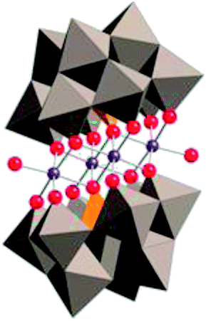
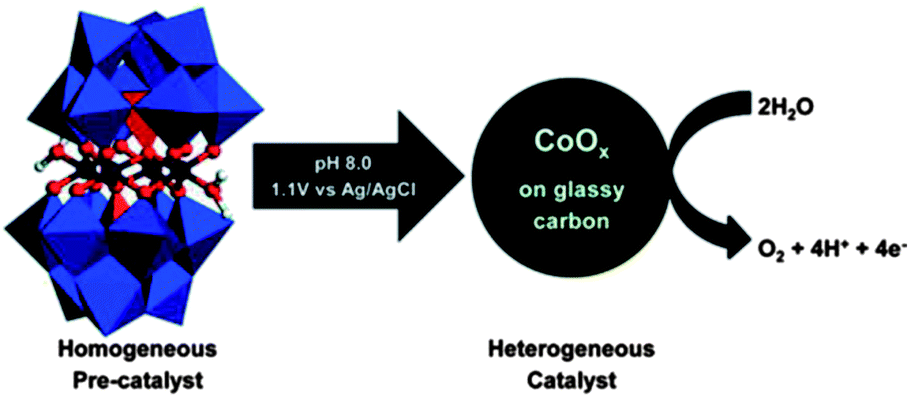
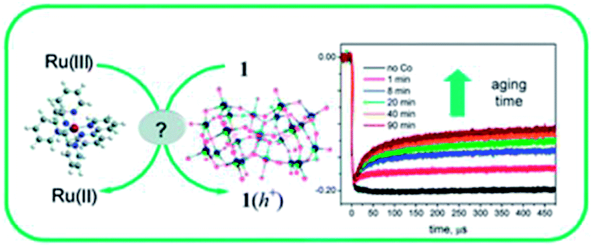
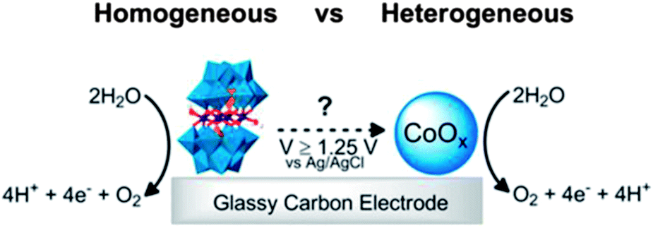
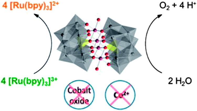
In the process of fuel generation, catalysts are exposed to either a highly reducing (H2 generation) or a highly oxidizing (O2 evolution) environment. Both of these environments challenge the stability of catalysts, so it is essential to assess the stability of such catalysts during product turnover. Performing such an assessment is particularly difficult when molecular catalysts are employed, due to the difficulty of determining the active species when only a trace amount of a molecular catalyst is present. Few reports distinguish, much less quantify, the amount of an active soluble catalyst (frequently the initial form of the catalyst) from a heterogeneous species that might be formed as the soluble species decomposes. This challenge is felt even more acutely in aqueous systems, such as those targeted in solar fuels research. A recent noteworthy example of a new technique for distinguishing a homogeneous catalyst from a heterogeneous catalyst produced by decomposition of the homogeneous species, developed by the Brudvig group,17 involves the use of an electrochemical quartz crystal nanobalance. The debate over the identity of the genuine catalytically active species present when the polyoxometalate water oxidation catalyst (WOC), [Co4(H2O)2(PW9O34)2]10− (Co4POM), is used has driven the development of new techniques. Two of these techniques, cathodic adsorptive stripping voltammetry and THpA+/toluene extraction followed by ICP-MS, were reported in a single article.18The progress of efforts to clarify the reactivity and stability of the molecular WOC, Co4POM, comprise an interesting and inspiring story that has been addressed in a series of papers from several groups. Indeed, the table of contents (TOC) graphics and the titles of the key papers tell the story concisely, as shown in the table below.
|
Title: A Fast Soluble Carbon-Free Molecular Water Oxidation Catalyst Based on Abundant Metals. |
| Hill, Science, 2010, 328, 5976, 342.18 | |
|
Title: Electrocatalytic Water Oxidation Beginning with the Cobalt Polyoxometalate [Co4(H2O)2(PW9O34)2]10−: Identification of Heterogeneous CoOx as the Dominant Catalyst |
| Finke, J. Am. Chem. Soc., 2011, 133, 14872.20 | |
|
Title: Is [Co4(H2O)2(α-PW9O34)2]10− a genuine molecular catalyst in photochemical water oxidation? Answers from time-resolved hole scavenging experiments |
| Bonchio, Chem. Commun., 2012, 48, 8808.21 | |
|
Title: Water Oxidation Catalysis Beginning with 2.5 μM [Co4(H2O)2(PW9O34)2]10−: Investigation of the True Electrochemically Driven Catalyst at ≥600 mV Overpotential at a Glassy Carbon Electrode |
| Finke, ACS Catal., 2013, 3, 1209.22 | |
|
Title: Differentiating Homogeneous and Heterogeneous Water Oxidation Catalysis: Confirmation that [Co4(H2O)2(α-PW9O34)2]10− Is a Molecular Water Oxidation Catalyst |
| Hill, J. Am. Chem. Soc., 2013, 135, 14110.18 |
Briefly, Hill et al. reported that Co4POM is a highly active molecular WOC in 2010.19 The following year, Finke et al. demonstrated using electrochemical experiments that the activity of Co4POM could be explained by the formation of a cobalt oxide (CoOx) film on the anode.20 Later, Bonchio et al. studied Co4POM using nanosecond-flash photolysis experiments that suggested that the catalyst was a soluble molecular species, but not Co4POM.21 Very recently, a follow-up paper by Finke et al. showed under different conditions that the catalytic activities of Co4POM and CoOx could not be unequivocally differentiated.22 However, these three studies involved different experiments under quite different experimental conditions and thus produced conflicting conclusions. The Hill group has completed a systematic study of the four variables (pH, ionic strength, buffer, and buffer concentration) that affect the thermodynamic stability of the catalyst. This work was published online in late August and the authors concluded:
“A central corollary here is that catalytic studies of molecular species, especially POM WOCs, under one set of experimental conditions should be compared only with extreme caution, if at all, to those under other conditions.”
The Hill study confirmed all the conclusions of the original paper,19 including the central thesis that the dominant catalyst under those original conditions was the Co4POM, and also explained how all of the other studies fit into a larger picture. The authors provided a new set of experiments that addressed the presence of multiple simultaneous WOCs in a POM system and allowed the reactivity of each species to be distinguished. A poster presented at ISACS 12 by C. Ottone et al. showed the successful attachment of this efficient WOC (Co4POM) to a TiO2 substrate (Poster 138, Book of Abstracts for this conference). The resulting electrode was examined using photoelectrochemical (PEC) experiments and an enhancement of the electrode performance compared to a bare electrode was demonstrated. Surface-science techniques showed that the Co4POM remained intact after photoelectrochemical tests, which was an exciting result for the polyoxometalate community.
In summary, ISACS 12, which partners with the journal Chemical Science, is a highly successful conference that draws together some of the most brilliant minds on the world in renewable energy research, and provide a platform for academic networking and exchanging ideas, as well as fostering the development of international collaborations in this field.
Z. Huang thanks an EES grant for travel and conference expenses and the authors all acknowledge DE-SC0004993 for support that allowed preparation of this manuscript.
References
- D. G. Nocera, Acc. Chem. Res., 2012, 45, 767–776 CrossRef CAS PubMed.
- S. Y. Reece, J. A. Hamel, K. Sung, T. D. Jarvi, A. J. Esswein, J. J. H. Pijpers and D. G. Nocera, Science, 2011, 334, 645–648 CrossRef CAS PubMed.
- N. S. Lewis, ECS Interface, 2013, 22, 43–49 CAS.
- A. Xiong, T. Yoshinaga, T. Ikeda, M. Takashima, T. Hisatomi, K. Maeda, T. Setoyama, T. Teranishi and K. Domen, Eur. J. Inorg. Chem., 2013 DOI:10.1002/ejic.201300439.
- T. J. Jacobsson, V. Fjällström, M. Sahlberg, M. Edoff and T. Edvinsson, Energy Environ. Sci., 2013, 6, 3676–3683 CAS.
- E. L. Miller and R. E. Rocheleau, Photochemical Hydrogen Production, Proceedings of the 2001 DOE Hydrogen Program Review, NREL/CP-570–30535 Search PubMed.
- S. Haussener, S. Hu, C. Xiang, A. Z. Weber and N. S. Lewis, Energy Environ. Sci., 2013, 6, 3605–3618 CAS.
- S. Hu, C. Xiang, S. Haussener, A. D. Berger and N. S. Lewis, Energy Environ. Sci., 2013, 6, 2984–2993 CAS.
- W. M. Ayers, J. Electrochem. Soc., 1982, 129, 1644 CrossRef CAS PubMed.
- R. E. Rocheleua, E. L. Miller and A. Misra, Energy Fuels, 1998, 12, 3–10 CrossRef.
- C. R. Cox, M. T. Winkler, J. J. H. Pijpers, T. Buonassisi and D. Nocera, Energy Environ. Sci., 2013, 6, 532–538 CAS.
- M. T. Winkler, C. R. Cox, D. Nocera and T. Buonassisi, Proc. Natl. Acad. Sci. U. S. A., 2013 DOI:10.1073/pnas.1301532110.
- S. Haussener, C. Xiang, J. M. Spurgeon, S. Ardo, N. S. Lewis and A. Z. Weber, Energy Environ. Sci., 2012, 5, 9922–9935 CAS.
- M. G. Walter, E. L. Warren, J. R. McKone, S.W. Boettcher, Q. Mi, E. A. Santori, and N. S. Lewis, Chem. Rev., 2010, 110, 6446–6473 CrossRef CAS PubMed.
- A. Kudo and Y. Miseki, Chem. Soc. Rev., 2009, 38, 253–278 RSC.
- J. R. McKone, N. S. Lewis, and H. B. Gray, Chem. Mater., 2013 DOI:10.1021/cm4021518.
- N. D. Schley, J. D. Blakemore, N. K. Subbaiyan, C. D. Incarvito, F. D'Souza, R. H. Crabtree and G. W. Brudvig, J. Am. Chem. Soc., 2011, 133, 10473–10481 CrossRef CAS PubMed.
- J. W. Vickers, H. Lv, J. M. Sumliner, G. Zhu, Z. Luo, D. G. Musaev, Y. V. Geletii and C. L. Hill, J. Am. Chem. Soc., 2013, 135(38), 14110–14118 CrossRef CAS PubMed.
- Q. Yin, J. M. Tan, C. Besson, Y. V. Geletii, D. G. Musaev, A. E. Kuznetsov, Z. Luo, K. I. Hardcastle and C. L. Hill, Science, 2010, 328, 342–345 CrossRef CAS PubMed.
- J. J. Stracke and R. G. Finke, J. Am. Chem. Soc., 2011, 133(38), 14872–14875 CrossRef CAS PubMed.
- M. Natali, S. Berardi, A. Sartorel, M. Bonchio, S. Campagna and F. Scandola, Chem. Commun., 2012, 48, 8808–8810 RSC.
- J. J. Stracke and R. G. Finke, ACS Catal., 2013, 3(6), 1209–1219 CrossRef CAS.
| This journal is © The Royal Society of Chemistry 2014 |