
 Open Access Article
 This Open Access Article is licensed under a Creative Commons Attribution-Non Commercial 3.0 Unported Licence
Cr1/3Zr2P3O12 with unusual tetrahedral coordination of Cr(III): peculiarities of the formation, thermal stability and application as a pigment
Nataliia
Gorodylova
*a,
Veronika
Kosinová
a,
Petra
Šulcová
a,
Petr
Bělina
a and
Milan
Vlček
bc
aDepartment of Inorganic Technology, Faculty of Chemical Technology, University of Pardubice, Doubravice 41, 532 10 Pardubice, Czech Republic. E-mail: NataliiaOleksandrivna.Gorodylova@upce.cz
bInstitute of Macromolecular Chemistry, Academy of Sciences of the Czech Republic, Heyrovsky sq. 2, 120 06 Prague, Czech Republic
cJoint Laboratory of Solid State Chemistry of Institute of Macromolecular Chemistry of the Academy of Sciences of the Czech Republic and the University of Pardubice, 532 10 Pardubice, Czech Republic
First published on 19th August 2014
Abstract
All the known chromium(III) NASICON-related phosphates are considered to be solid solutions. In these compounds chromium atoms share their position in the basic framework of the crystal lattice with other structure forming elements such as zirconium. In our study, we have hypothesised a completely new way of structural organisation of the chromium(III) zirconium(IV) NASICON framework, consisting in the distribution of chromium over the charge-compensating atom sites with tetrahedral oxygen coordination. The possibility of formation of the corresponding phosphate, Cr1/3Zr2P3O12, was studied using a classical ceramic route and a sol–gel method. Structural affiliation of the obtained pure phase product was studied using XRD analysis. The results confirmed that the Cr1/3Zr2P3O12 phosphate belongs to monoclinic SW-subtype of the NASICON family. In this structure, chromium atoms occupy charge-compensating sites with a strongly distorted tetrahedral oxygen environment. To the best of our knowledge, it is the first example of tetrahedral coordination of chromium(III) in phosphates. Along with the unusual crystallographic characteristics of chromium, special attention in this paper is devoted to the thermal stability of this phosphate and to its performance as an inorganic pigment. The sample was characterised by heating microscopy and DTA study, particle size distribution analysis, and IR- and VIS-spectroscopy. The stability of the obtained powder in a glaze environment, its colouring performance and lightfastness are discussed as well.
Introduction
During the last thirty years a considerable part of research in the field of phosphate chemistry has been focused on the investigation of NASICON-related compounds (NASICON is an acronym for NAtrium Super Ionic CONductor, Na1+xZr2SixP3−xO12). Numerous framework phosphates of this family have been intensively studied for a range of practical applications, in particular as low thermal expansion ceramics,1,2 solid electrolytes,3,4 host materials for radioactive waste immobilisation,5 catalysts6,7 and pigments.8–10 Originally, the term “NASICON” only referred to compounds of rhombohedral symmetry isostructural to the original prototype, NaZr2P3O12, which is also commonly known as NZP.11 Nowadays, a wide variety of non-isostructural compounds containing the [M4IV(PO4)6] structural fragment and possessing electronic conductivity are classified to the NASICON-family too. Considering lattice symmetry, common NASICONs embrace rhombohedral (R![[3 with combining macron]](https://www.rsc.org/images/entities/char_0033_0304.gif) c, R, R2, R-c, R-, P, Pc1), orthorhombic (Pbcn) and monoclinic (C2/c and P21/n) crystal systems and on this basis the NASICONs are divided into several subtypes. In particular, NASICONs of Rc and R point groups are isostructural to the original NASICON prototype, NaZr2P3O12, and are sub-classified as NZP-subtype; NASICONs belonging to R2, R-c, R-, P and Pc1 point groups are isostructural to CaZr2P3O12 (CZP-subtype); NASICONs of P21/n and Pbcn point groups are structurally related to scandium wolframate, Sc2W3O12, and thus, sub-classified as the SW-subtype. All subtypes deriving from NASICON differ mainly in the packing and/or orientation of [M4IV(PO4)6] structural fragments. Basically, within the [M4IV(PO4)6] polyhedral interconnection, two types of interstitial sites are created for charge compensating ions “A”, one of which is structurally forming and connects [M4IV(PO4)6] groups, while the other one is created in framework cavities.11–14 The ability of the phosphate units to rotate without breaking the existing symmetry determines the flexibility of the NASICON three-dimensional skeleton toward cationic substitutions and the existence of numerous chemical compositions. In particular, the basic framework sites besides MIV = Ti, Zr, Hf, Ge, Sn, Mo, some Ln and An, can also be substituted by trivalent Cr, Fe, Sc, In or Yb, as well as by quinquivalent Nb, while the interstitial sites can be empty, partially or fully occupied by s-, p-, d- and/or f-elements of the oxidation state from +1 to +3 with radii ranging from H+ to Cs+.12
c, R, R2, R-c, R-, P, Pc1), orthorhombic (Pbcn) and monoclinic (C2/c and P21/n) crystal systems and on this basis the NASICONs are divided into several subtypes. In particular, NASICONs of Rc and R point groups are isostructural to the original NASICON prototype, NaZr2P3O12, and are sub-classified as NZP-subtype; NASICONs belonging to R2, R-c, R-, P and Pc1 point groups are isostructural to CaZr2P3O12 (CZP-subtype); NASICONs of P21/n and Pbcn point groups are structurally related to scandium wolframate, Sc2W3O12, and thus, sub-classified as the SW-subtype. All subtypes deriving from NASICON differ mainly in the packing and/or orientation of [M4IV(PO4)6] structural fragments. Basically, within the [M4IV(PO4)6] polyhedral interconnection, two types of interstitial sites are created for charge compensating ions “A”, one of which is structurally forming and connects [M4IV(PO4)6] groups, while the other one is created in framework cavities.11–14 The ability of the phosphate units to rotate without breaking the existing symmetry determines the flexibility of the NASICON three-dimensional skeleton toward cationic substitutions and the existence of numerous chemical compositions. In particular, the basic framework sites besides MIV = Ti, Zr, Hf, Ge, Sn, Mo, some Ln and An, can also be substituted by trivalent Cr, Fe, Sc, In or Yb, as well as by quinquivalent Nb, while the interstitial sites can be empty, partially or fully occupied by s-, p-, d- and/or f-elements of the oxidation state from +1 to +3 with radii ranging from H+ to Cs+.12
The astonishing variety of substituent combinations makes the basic NASICON framework ideally suited for the development of various compositions meeting the requirements of the specific application. The derived extensive possibilities for chemical modifications in combination with excellent thermal stability and leaching resistance of NASICONs make this class of phosphates also extremely attractive for application as thermally stable colourants. Our research group at the University of Pardubice is highly interested in the development of new thermally stable ceramic pigments and while considering the colouring performance of NASICON compounds, we recently reported excellent purple-blue colourants based on Co0.5Zr2P3O12 for application in ceramic glazes.10 Due to the high performance characteristics of the described phosphates, we continue our investigation in this area and, in particular, zirconium phosphates containing chromium(III), which provide saturated green or pink colour shades, have interested us as prospective material for pigmentary application. Several NASICON-based potential colourants containing chromium(III) have been already described by different research groups worldwide.15–17 It was shown that the chromatic characteristics of Cr-NASICON pigments strongly depend on co-substitutions in the structure. Specifically, the variation of the chemical composition of charge compensating ions and the degree of substitution allow us to control the crystal field strength and the covalence factor which act on the chromophore Cr3+ and thus the visual appearance of the pigments. For example, solid solutions Na1+xZr2−xCrxP3O12 and Ca(1+x)/2Zr2−xCrxP3O12 provide green, beige, grey or pink shades depending on the degree of substitution “x”.16 The described compounds are stable at high temperatures and were used for colouration of glazes. Moreover, scientific interest in chromium NASICON compounds is not limited by their pigmentary application. Several compositions were reported to possess superionic conductivity (Li2CrMIVP3O12 (MIV = Ti, Zr, Hf), Li1+xCrxHf2−xP3O12, Na2(LaCr)ZrP3O12, Na3Cr2P3O12, Na1+xZr2−xCrxP3O12![[thin space (1/6-em)]](https://www.rsc.org/images/entities/char_2009.gif) 18–24) or as being an attractive geological medium for nuclear waste immobilisation (MIICrZrP3O12, MII = Sr, Ba, Pb25).
18–24) or as being an attractive geological medium for nuclear waste immobilisation (MIICrZrP3O12, MII = Sr, Ba, Pb25).
As follows from the discussed studies,15–25 all the discovered chromium(III) NASICON-related phosphates can be considered as solid solutions in M3ICr2P3O12–MIM2IVP3O12 or Cr2P3O12–P3O12 systems, where chromium atoms share the basic framework position in the crystal lattice with other structure forming elements such as zirconium. However, there is another potential way of structural organisation of the chromium(III) zirconium(IV) NASICON framework, consisting in the distribution of chromium atoms over the charge-compensating sites A. Taking into account the required electroneutrality of the resulting compound, the formula of such a potential chromium zirconium phosphate, containing [Zr4IV(PO4)6] structural fragments, may be presented as Cr1/3Zr2P3O12. In order to find out which of the NASICON subtypes is structurally the most suitable for Cr1/3Zr2P3O12, it is necessary to analyse the compositionally related NASICONs in more detail. A group of isostructural double zirconium phosphates containing lanthanides, Ln1/3IIIZr2P3O12,24,26 is compositionally the closest to Cr1/3Zr2P3O12. The crystal structure of these phosphates belongs to the CZP-subtype (sp. gr. R, recently refined to Pc1 or P26), where rare earth atoms occupy A sites, i.e. compensating ion position within an octahedral oxygen environment. In addition, the crystal structure of other related phosphates containing large-sized divalent cations (M0.5IIZr2P3O12, MII = Sr, Cd, Ba, Pb) was characterised as isostructural to CZP too. However, substantial size difference between all these elements and chromium(III), which is, for example, for the smallest lanthanide, Yb(III), more than 1.4 times larger than that for Cr(III) in octahedral coordination,27 may not allow realisation of the CZP lattice symmetry for the Cr1/3Zr2P3O12 composition. The crystal structure of another group of related compounds containing smaller divalent metals, M0.5IIZr2P3O12 where MII = Mg, Mn, Co, Ni, Cu, Zn, is distorted to monoclinic symmetry (the SW-subtype, sp. gr. P21/n).12 The main distinction between the SW and CZP subtypes is the symmetry conversion of the structure forming sites A (I) from octahedral (in CZP) to a strongly distorted tetrahedral oxygen environment (in SW). Thus, with respect to the ion radii of chromium(III), the crystal structure of the Cr1/3Zr2P3O12 phosphate may be rather isostructural to SW-subtype. However, tetrahedral coordination is very uncommon for chromium(III) and its realisation with oxygen has been reported only for a few spinels.28–33 To the best of our knowledge, chromium(III) occupies octahedral positions in all known phosphates. The preferable octahedral coordination of chromium(III) can be explained in terms of crystal field stabilisation energy and, specifically, octahedral site preference energy, which is one of the highest for d3 electronic configuration of Cr(III).32,34 Thus, from the point of view of crystallographic preference of Cr(III), its location in the charge-compensating tetrahedral sites of the SW lattice may cause some constraint and instability of the resulting structural formation.
This paper examines whether the considered concept makes sense and verifies the possibility of formation of Cr1/3Zr2P3O12. For the synthesis, we have employed two different approaches, and special attention in our study is devoted to the thermal stability of the obtained phase and its characterisation as an inorganic pigment.
Experimental part
Materials and methodology
Two different approaches were used for synthesis: solid state reaction and the sol–gel method. In the first case we used Cr2O3 (P., Lachema, CZ), ZrO2 (P.A., Sepr, FR) and (NH4)2HPO4 (P.A., Lachema, CZ) as initial reagents. A stoichiometric powder mixture was thoroughly ground in an agate mortar with a pestle and transferred into an agate milling form and homogenised by ball-milling in a planetary mill (Pulverisette 5, Fritsch, DE). In order to obtain a thick suspension, an appropriate amount of acetone was added. The rotation speed was 200 rpm and the homogenisation time – 2 h. After this procedure the obtained suspension was completely dried overnight in open air and subjected to further thermal treatment. Calcination was performed in an electric furnace in several steps: 200 °C for 4 h, 300 °C for 4 h (heating rate of 5 °C min−1); regrinding and further calcination at temperatures of 800, 1000 and 1200 °C (heating rate of 5 °C min−1) with an exposure time of 24 h at each step.The synthesis procedure of the sol–gel (SG) method was performed as follows: stoichiometric amounts of CrCl3·6H2O (P., Lachema, CZ) and ZrOCl2·8H2O (P.A., Merck, DE) were separately dissolved in distilled water with addition of a little amount of HCl (P.A., Penta, CZ). The zirconium solution was added dropwise to the chromium solution while constantly stirring. Afterwards, an appropriate amount of 1 M solution of (NH4)2HPO4 was added dropwise to this mixture while it was continuously heated at a temperature of 70 °C and constantly stirred to maintain uniform mixing. A gelatinous precipitate began to form immediately after addition of the phosphate solution. After complete mixing, the gelled suspension was maintained under stirring for some hours, dried overnight at 60 °C and exposed to calcination. At the first stage the sample was continuously heated at a temperature of 600 °C for 24 h (heating rate of 5 °C min−1) in order to remove all volatile residues. After this, the ground powder was calcined similarly to the solid state reaction method (800, 1000 and 1200 °C).
Characterisation techniques
Crystallochemical characterisation of the calcined powders was performed by X-ray diffraction analysis (a Diffractometer D8 Advance, monochromatic CuKα radiation and a scintillation detector, Bruker, GB). Data were collected by step scanning over the 2θ range from 10° to 80° with a step size of 0.02° and 3 s counting time at each step. Thermal behaviour of the reaction mixtures and the final product of Cr1/3Zr2P3O12 was investigated using simultaneous differential thermal and thermogravimetric analysis (DTA-TGA, Jupiter STA 449/C/6/F, Netzsch, DE) with temperature intervals between 20 and 1400 °C and a heating rate of 10 °C min−1. α-Al2O3 was used as a reference material and the mass of the sample was ∼150 mg. The thermal stability of Cr1/3Zr2P3O12 was tested using a heating microscope equipped with automatic image analyser (EM201-12, Hesse Instruments, DE). The equipment was calibrated using Sn, In, Al, Zn and its standard measurement uncertainty typically is ≤5 °C. For the measurement, a pellet of cylindrical form with dimensions of 3 × 3 mm was prepared manually using ethanol as a binding agent. The test was performed with temperature intervals between 20 and 1400 °C and a heating rate of 10 °C min−1. Particle size distribution of the sample was measured using a laser scattering system based on Fraunhofer bending (Mastersizer 2000/MU, Malvern Instruments, UK). Milling of the sample was performed using a laboratory planetary mill (Pulverisette 5, Fritsch, DE). Scanning electron microscopy (SEM) was used to characterise the obtained sample with respect to particle size, homogeneity, morphology and microstructure (JOEL JSM-5500 LV apparatus equipped with analyser IXRF systems and a detector Gresham Sirius 10, Joel Inc., USA). The IR spectrum of Cr1/3Zr2P3O12 powder pressed in a pellet with potassium bromide was measured using SPECORD M80 (Carl Zeiss, Jena, DE) in the region of 300–1800 cm−1. The colour of the sample was evaluated by measurement of spectral reflectance in the visible region of light (400–700 nm) using a ColorQuest XE (HunterLab, USA). The measurement conditions were as follows: an illuminant D65, 10° standard observer and measuring geometry d/8°. The colour properties are described in terms of the CIELAB system recommended by CIE (Commission Internationale de l'Eclairage35). The measurement was done in triplicate and the average value was chosen as its result for each colorimetric parameter. The standard deviation of the measured colorimetric parameters was <0.10 and the relative standard deviation was ≤1%, indicating that the measurement error can be ignored. The measurement was performed for Cr1/3Zr2P3O12 powder, which was manually pressed into a quartz cuvette, and for enamelled samples. The milled powder was enamelled with two types of commercial single-firing glazes (G 05 091 and G 070 91, Glazura, CZ) in an amount of 10% wt onto conventional ceramic biscuits (950 °C, 15 min, 10 °C min−1). The interaction between the pigment particles and the melted glazes was also investigated using the SEM technique and powder XRD analysis. Finally, the colour stability of the enamelled samples at daylight was tested with a Q-panel test chamber (Q-Sun Xe-1-S Xenon Test Chamber, Lab. Products, USA). The samples were exposed to a xenon-arc light source for 1000 h with an irradiance setting at 340 nm and 0.51 W m2. A standard program for lightfastness measurement was employed (step 1: light, 3.48 h, 65 °C; step 2: dark, 1 h, 45 °C; step 3: back to step 1) and the colour evaluation was performed after every 250 h.Results and discussion
X-ray diffraction characterisation (XRD)
XRD patterns of the samples (SSR) are shown in Fig. 1. Phase composition analysis revealed that upon calcination of the reaction mixture, interaction between the initial components mainly led to the formation of the ZrP2O7 phase. At lower temperatures the mixture contained some amount of unreacted Cr2O3 and ZrO2, while only at 1200 °C a NASICON-related phase, which was identified as Zr3(PO4)4, appeared as well. In our experiment we used a monoclinic modification of ZrO2 as the zirconium source, which is known to be less reactive. It may provide a reasonable explanation for the low reactivity of the reaction mixture at lower temperatures and the observed results. The reactivity of powders in a solid state reaction can be improved through different approaches such as, for example, a pre-treatment procedure involving mechanochemical activation or by using low melting mineralisers. However, on the basis of our experience with Co0.5Zr2P3O12,10 we decided to use a completely different synthesis approach in order to achieve the formation of a single phase product of Cr1/3Zr2P3O12.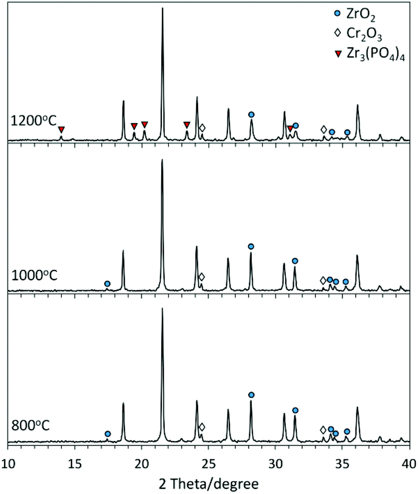 | ||
| Fig. 1 XRD patterns of the samples prepared by solid state reaction (unmarked phase: ZrP2O7). | ||
The second employed method was sol–gel. Technically it is much more complicated than the conventional ceramic route; however, it often allows us to obtain a pure single phase product at low temperatures where a simple solid state reaction fails.10 XRD patterns of the samples are shown in Fig. 2. A NASICON-related single phase product was only detected at 800 °C and an increase of calcination temperature up to 1000 °C and 1200 °C led to its decomposition and formation of additional zirconium and chromium phosphates.
 | ||
| Fig. 2 XRD patterns of the samples prepared by the sol–gel method. | ||
The XRD pattern of the sample Cr1/3Zr2P3O12 (SG, 800 °C) was indexed using FullProf software36 and the calculated unit cell parameters are specified in Table 1. The analysis of the XRD pattern suggested a primitive monoclinic lattice symmetry P2/m. According to the rules which were formulated for distinguishing the monoclinic distortions of the NASICON family using the powder XRD method,13 the obtained compound Cr1/3Zr2P3O12 belongs to the monoclinic P21/n space group and can be classified as the NASICON SW-subtype. In order to support this conclusion we have analysed the available crystallographic information for other representatives of SW-subtype (Table 1). As follows from the comparative analysis, the similarities between the chemical formulas of Cr1/3Zr2P3O12 and SW representatives of M0.5IIZr2P3O12 (MII = Mg, Mn, Co, Ni, Cu, Zn), their identical diffraction patterns (ICDD# 00-041-0040, 00-053-0955, 00-045-0015, 00-053-0956, 00-045-0014, 00-047-0412, 00-053-0957, 00-053-0958), the closeness of the lattice parameters and the identical space group of these compounds (see Table 1) indicate a common basis for the formation of their crystal structures. This allows us to firmly conclude that Cr1/3Zr2P3O12 is isostructural with M0.5IIZr2P3O12 and that it belongs to NASICON-related SW-subtype. On the basis of the already known structure of one of the representatives of the group, Ni0.5Zr2P3O12,13 it is also possible to make some conclusions concerning the Cr1/3Zr2P3O12 crystal structure. The most important issue concerns the crystallographic position of charge-compensating ions in the crystal lattice: identically to Ni(II), ions of Cr(III) occupy charge-compensating sites A within a strongly distorted tetrahedral oxygen environment. It is worthwhile to note that to the best of our knowledge this is the first example of tetrahedral coordination of chromium(III) in phosphates.
| Chemical formula | Ionic radiia | Space group | a/Å | b/Å | c/Å | β/° | V/Å3 | Z | Reference |
|---|---|---|---|---|---|---|---|---|---|
| a Ionic radii are specified for the divalent elements with coordination number IV and chromium(III) with coordination number VI (the only available).27 | |||||||||
| Mg0.5Zr2P3O12 | 0.57 | P21/n | 12.384(3) | 8.922(3) | 8.844(3) | 90.56(2) | 977.1 | 4 | 14 |
| 12.426 | 8.903 | 8.836 | 89.62 | 977.49 | 37 | ||||
| 12.4218(2) | 8.9025(2) | 8.8218(2) | 90.466(1) | 975.527 | 28 | ||||
| Mn0.5Zr2P3O12 | 0.66 | P21/n | 12.390(3) | 8.931(4) | 8.843(3) | 90.55(1) | 978.5 | 4 | 14 |
| 12.426 | 8.903 | 8.836 | 89.62 | 977.49 | 41 | ||||
| Co0.5Zr2P3O12 | 0.58 | P21/n | 12.389(3) | 8.928(3) | 8.840(2) | 90.54(1) | 977.7 | 4 | 14 |
| 12.43 | 8.924 | 8.853 | 90.35 | 982.32 | 41 | ||||
| Ni0.5Zr2P3O12 | 0.55 | P21/n | 12.385(3) | 8.924(4) | 8.840(3) | 90.53(1) | 977.1 | 4 | 14 |
| 12.388(1) | 8.9269(7) | 8.8449(7) | 90.55(1) | 978.1 | 13 | ||||
| Cu0.5Zr2P3O12 | 0.57 | P21/n | 12.389(3) | 8.925(4) | 8.841(3) | 90.53(1) | 977.4 | 4 | 14 |
| Zn0.5Zr2P3O12 | 0.6 | P21/n | 12.389(2) | 8.929(3) | 8.842(2) | 90.54(1) | 978.1 | 4 | 14 |
| Cr1/3Zr2P3O12 | 0.615 | P21/n | 12.380(4) | 8.921(3) | 8.838(2) | 90.52(1) | 976.1 | 4 | — |
The appearance of additional impurity phases above 800 °C in XRD patterns indicates degradation of Cr1/3Zr2P3O12 at higher temperatures. The instability of this phase can be connected with constraints of the Cr1/3Zr2P3O12 structural organisation induced by energetically disadvantageous coordination of chromium(III). In addition, the structural constraints can be caused by low occupancy of charge compensating sites, which is only 1/3 in Cr1/3Zr2P3O12 in comparison with 1/2 in M0.5IIZr2P3O12. It is worth mentioning that several related NASICONs also possess limited phase stability at high temperatures. For example, isostructural phosphates Mg0.5Zr2P3O12 and Co0.5Zr2P3O12 degrade at temperatures above 1200 °C yielding Zr2O(PO4)2 as an impurity phase. Other compounds of an analogous composition, Ln1/3Zr2P3O12, where the occupancy of the charge compensating site is as low as in Cr1/3Zr2P3O12, already decompose at temperatures above 900 °C.10,24,37 In contrast, rhombohedral NASICON phases containing chromium(III) at basic framework positions with octahedral coordination (Na1+xZr2−xCrxP3O12 and M(1+x)/2Zr2−xCrxP3O12, M = Cd, Ca, Sr) show improved thermal stability (above 1300 °C).15,16 Thermal behaviour of the obtained phosphate is discussed in more detail in the next section.
Thermal analysis (DTA-TGA) of the reaction mixtures and thermal stability of Cr1/3Zr2P3O12
The differential thermal and thermogravimetric (DTA-TGA) analysis was performed in order to reveal physical transformations, which accompanied chemical transformations in the mixtures during heating. In the case of solid state reaction, the analysis of the powder was performed after the ball-milling stage and drying in open air. The observed thermoanalytical curves are presented in Fig. 3(a). | ||
| Fig. 3 DTA-TGA curves of the reaction mixtures: (a) solid state reaction; (b) sol–gel method. | ||
Two main reaction stages can be distinguished from the presented data. The first stage is accompanied by a dual endothermic effect on the DTA curve between 120 and 300 °C and by a substantial mass loss (∼15%). These effects can be connected with thermal transformations of diammonium hydrophosphate, in particular elimination of ammonia and melting. According to our calculations, the release of two molecules of ammonia of (NH4)2HPO4 in the reaction mixture leads to ∼15.2% of mass loss, which perfectly matches the observed value of 15%. The second stage is accompanied by a weak endothermic effect and a step-like mass loss (∼9%), which correspond to dehydration of the phosphate-component and interaction between the reagents. This can be also connected with intermolecular dehydration of phosphate resulting in the formation of pyrophosphate ZrP2O7, which is the main reaction product according to the XRD data. The total mass loss of the sample constitutes 28.4%, which is in good agreement with the calculated value for the starting mixture (28.5%).
The dried precursor, which was obtained by the sol–gel method, was examined using the same technique. The obtained thermoanalytical curves are shown in Fig. 3(b) and several overlapping stages can be distinguished from the presented data. The first weak endothermic effect with a minimum at 150 °C and associated mass loss of ∼5% can be connected with dehydration of the mixture. Due to a high number of options for polymerisation of the phosphate component and an unknown content of the remaining water in the dried precursor, it is difficult to estimate the theoretical value of mass loss which is connected with this process even approximately. The next strong endothermic effect takes place around 330 °C and is accompanied by substantial mass loss. This was attributed to decomposition of ammonium chloride (Td = 338 °C), which forms during the drying stage of the gel. Theoretical calculation provides a number of ∼33% (if all chloride in the mixture is bound with ammonium), which correlates well with the observed value of 30%. The next endothermic effects and gradual mass loss can be associated with further dehydration and interaction in the mixture. The mass loss stopped around 800 °C, where the single phase of Cr1/3Zr2P3O12 was detected in XRD patterns.
The Cr1/3Zr2P3O12 single phase product (SG, 800 °C) was subjected to further thermal analysis in a temperature range of 20–1400 °C using two approaches: heating microscopy and DTA-TGA. Analysis by heating microscopy commonly provides results on thermal resistance and sintering of the ceramic powders at high temperatures. Results of this measurement are presented in Fig. 4. The curve represents the change of the sample area during temperature increase. The sample silhouettes correspond to the starting (27 °C) and final (1416 °C) points of the measurement. The detected curve shows that the sintering of Cr1/3Zr2P3O12 started just below 900 °C, intensively progressed up to 980 °C and slowed down above this temperature. If we compare these results with our previous research on Co0.5Zr2P3O12,10 some correlations between thermal behaviour of these NASICON-related phosphates can be found as well. Our previous study revealed that the SG-method provided lower thermal stability of the samples in comparison with SSR. The shrinkage of the cobalt phosphate which was obtained with the SG technique progressed very fast above 950 °C, while the composition degradation was observed only above 1200 °C. In the case of Cr1/3Zr2P3O12, the observed shrinkage above 900 °C is certainly connected with phase degradation of this phosphate as well. Very similar results were also observed for analogous compounds of zirconium and lanthanides, Ln1/3Zr2P3O12. In particular, it was reported that the thermal stability range of these phosphates is limited to 900 °C due to their decomposition, which prevents sintering at higher temperatures.24 This similarity in thermal instability between the lanthanides and chromium phosphates probably is connected with their common structural peculiarities and in particular with the very low occupancy of charge-compensating sites, which in both cases is only 1/3.
 | ||
| Fig. 4 Heating microscopy results of Cr1/3Zr2P3O12 (SG, 800 °C) representing the decrease of the sample areas with a temperature increase. | ||
In order to gain more information about the sintering and degradation processes of Cr1/3Zr2P3O12, DTA of the sample was also performed under the same conditions as with heating microscopy analysis. The obtained DTA curve (Fig. 5) can be characterised by a dominant endothermic decrease, where only one exothermic effect with an extremum at 977 °C is observed. This effect is not present at the DTA curve of the reaction mixture (Fig. 3) and thus, it must be characteristic of the Cr1/3Zr2P3O12 phase. In our opinion it can be connected with crystallisation of a new phase, which is a product of decomposition of Cr1/3Zr2P3O12. Most probably it is ZrP2O7, because it is the main phase which was detected by XRD analysis after 24 h of exposure at 1000 °C (Fig. 2). The slight flattening of the sintering curve which was observed around 980 °C in the previous experiment using heating microscopy (Fig. 4) can also be connected with the appearance of ZrP2O7 in the phase composition. It is well known that this pyrophosphate possesses enhanced thermal characteristics and its formation could slow down the process of sintering of the sample.
 | ||
| Fig. 5 DTA curve of Cr1/3Zr2P3O12 (SG, 800 °C). | ||
Particle size distribution and morphology
For application as a ceramic pigment, it is important to determine the particle size distribution of the powder, which strongly affects colour homogeneity, surface appearance and gloss of enamelled bodies. Generally, for ceramic pigments it is recommended that the median particle size (d[50]) passes in a range of 0.1–10 μm. Considering the application in glazes, d[50] values between 1 and 10 μm are optimal in order to achieve good hiding power and at the same time to provide resistance to the dissolution of pigment particles during glazing. Particle size distribution of Cr1/3Zr2P3O12 (SG, 800 °C) was measured after preliminary manual grinding of the powder in an agate mortar with a pestle. The volume distribution of particles according to their size is presented as a histogram on the logarithmical scale in Fig. 6. The observed distribution is non-symmetrical with a mode at 30 μm. Other important size values are summarised in the top left corner of the figure. The specified volume-basis median value (d[50] = 14.76 μm), which splits the volume distribution into two halves, is below the mode value. The distribution width was calculated according to the formula: Span = (d[90] − d[10]) × d[50]−1 = 3.27 μm. The observed particle size distribution parameters are higher than what is recommended for pigments for application in glazes; thus a milling procedure is required for the sample. Milling was performed in a laboratory planetary mill (200 rpm) in an agate milling form in acetone media with addition of a grinding filling (in the mass ratio 1:10, type ZY, fraction 1.6–1.4 μm, SiLyheads, DE). In order to obtain the desired size distribution, 10 minutes of milling under specified conditions is sufficient for this powder. The resulting median size is 5.17 μm and the distribution width is reduced to 2 μm.
 | ||
| Fig. 6 Particle size distribution of Cr1/3Zr2P3O12 (SG, 800 °C). | ||
In order to gain further information about the particle size, morphology and homogeneity of the powder, SEM characterisation was also performed (Fig. 7). As follows from the SEM observations, the unmilled sample is formed from aggregates of different sizes, as well as from smaller disconnected particles of irregular shape. On the image with lower magnitude (50 μm scale), two distribution ranges are clearly observed: massive aggregates (∼20–50 μm) and dominating little particles (∼1–10 μm). The obtained results correlate well with the particle size distribution measurement and the observed non-symmetric form of the distribution histogram.
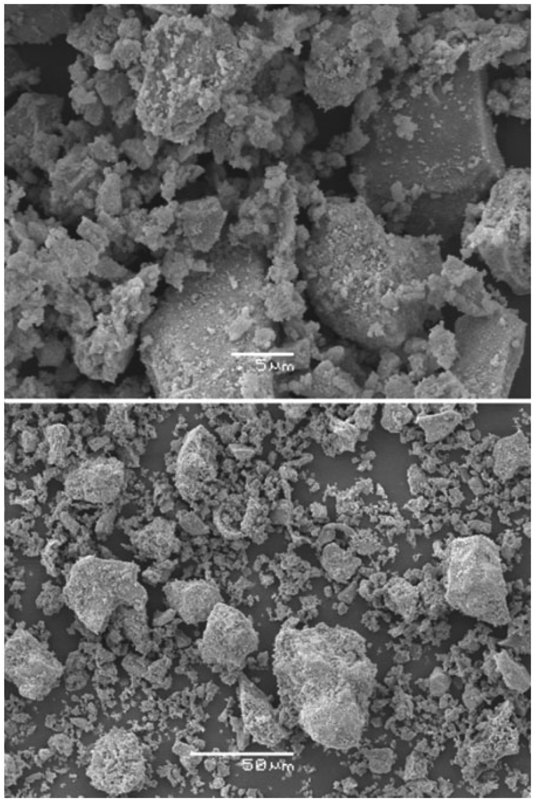 | ||
| Fig. 7 SEM images of Cr1/3Zr2P3O12 (SG, 800 °C). | ||
Spectral characterisation (IR and VIS) and lightfastness
For a more complete characterisation, the obtained Cr1/3Zr2P3O12 phase (SG, 800 °C) was analysed by IR spectroscopy. In general, the vibrational modes of the NASICON-related compounds can be attributed to external and internal modes of PO4 tetrahedra, and also to lattice modes including the motion of the metallic ions in their oxygen environment. The PO4 external modes correspond to librational and translational motions of these groups and are observed below 300 cm−1,38 which, in our case, is beyond the measured range (300–1800 cm−1). In turn, the internal modes of the isolated phosphate groups represent a symmetric/antisymmetric degenerate of phosphorous nonbridging oxygen stretchings (ν1/ν3), and symmetric/antisymmetric degenerate bendings (ν2/ν4). For the isolated phosphate groups of the ideal Td symmetry only the ν3 and ν4 vibrations are IR active; however, in the crystalline structure the symmetry of the PO4 group is distorted by lattice environment, changing the situation dramatically. The monoclinic NASICONs are characterised with 3 independent phosphorus positions of the C1 site group and the monoclinic C2h factor group. According to factor group analysis, 27 IR active bands of internal vibrations are expected to appear for these compounds.14The IR spectrum of Cr1/3Zr2P3O12 is shown in Fig. 8. At the spectrum, a band between 300 and 400 cm−1 can be attributed to the MO motions, the next group of badly resolved bands between 450 and 700 cm−1 – to the symmetric/antisymmetric degenerate OPO bendings – and a non-resolved broad band between 900 and 1300 cm−1 – to the symmetric/antisymmetric degenerate of PO stretchings. Comparing the structure of the better resolved spectrum part between 450 and 700 cm−1 with related NASICONs of monoclinic and rhombohedral symmetries, we came to the conclusion that the complexity of this part of the Cr1/3Zr2P3O12 spectrum also testifies in favour of the monoclinic lattice of this compound.14 In addition, the broad absorption band between 900 and 1300 cm−1 with an almost unresolved component structure indicates the presence of a short-range static disorder in the lattice. Probably, it can be connected with the mobility of the chromium atoms over the predominantly vacant sites A.38 A weak band between 1600 and 1700 cm−1 can be attributed to the presence of some traces of water, which is mainly connected with the technical aspect of the measurement, in particular, the use of the hygroscopic potassium bromide for the preparation of the pellet.
 | ||
| Fig. 8 IR spectrum of the Cr1/3Zr2P3O12 sample (SG, 800 °C). | ||
The colouration of the obtained sample was characterised using VIS spectroscopy by measuring spectral reflectance in the visible region of light. The measurement was performed both for the Cr1/3Zr2P3O12 powder (SG, 800 °C), which was manually pressed into a quartz cuvette, and for the enamelled samples. The colour of the samples is described in terms of the CIELAB system. In this system, the values of a* (the green (−) → red (+) axis) and b* (the blue (−) → yellow (+) axis) indicate the colour hue (h°), and the value of L* represents the lightness or darkness of colour as related to a neutral grey scale (which is described by numbers from 0 (black) to 100 (white)). The parameter C* (chroma) represents saturation of the colour (C* = (a*2 + b*2)0.5) and h° represents the hue angle which characterises the colour shade (h° = arctangent (b*·a*−1·360°·(2 × 3.14)−1). The obtained colour parameters are summarised in Table 2. The powdered sample has a green shade and the calculated value of its colour hue (h°) indicates some shift from pure green (120°) to yellow (51–60°). The enamelled samples have a saturated bright green colouration with a colour hue of 120.4° and 123.3°, which is very close to a pure green hue (120°) (Fig. 9). The colour of the sample which was enamelled with glaze G 050 91 is more saturated and is a bit lighter than that with glaze G 070 91. At the same time, the saturation of both the enamelled samples is almost 3 times higher than that of the powder. This can clearly be observed from the reflectance spectra in Fig. 10, where a higher absorption of the wavelengths discrepant from green and higher reflection of green (492–577 nm) in the visible range of the electromagnetic spectrum indicates a higher intensity of the resulting green shade (Fig. 10).
 | ||
| Fig. 9 Enamelled Cr1/3Zr2P3O12 sample (SG, 800 °C), glazes G 050 91 and G 070 91. | ||
 | ||
| Fig. 10 Electronic reflectance spectra of powdered and enamelled Cr1/3Zr2P3O12 samples (SG, 800 °C, glaze G 050 91). | ||
| Sample | L* | a* | b* | C* | h° |
|---|---|---|---|---|---|
| Powder | 62.3 | −2.7 | 10 | 10.4 | 105.1 |
| Enamelled, glaze G 050 91 | 66.1 | −14.3 | 24.3 | 28.2 | 120.4 |
| Enamelled, glaze G 070 91 | 65.0 | −14.1 | 21.5 | 25.7 | 123.3 |
The colour of the samples can be explained by the formalism of the crystal field theory applied to Cr(III). It has a d3 electronic configuration and in the SW structure it occupies the sites with a distorted tetrahedral coordination. Accordingly, two main absorption bands, which correspond to 4T1 → 4T2 and 4T1 → 4A2 transitions, appear in the visible part of the spectrum (Fig. 10). The form and position of these bands are crucial for the colour perceived by the human eye. For example, high and low energy shifts of the absorption bands result in pink shades, while a middle position gives rise to a deep green colour. For our samples it is 16393 cm−1 (610 nm) and 21978 cm−1 (455 nm), which are intermediate, and the values are typical for green coloured compounds. As earlier discussed in the Introduction, tetrahedral oxygen coordination is very uncommon for chromium(III) and was reported before only for several spinels.28–33 Unfortunately, optical characterisation of these compounds was performed only for a few inverted spinels based on LiGa5−xCrxO8, where chromium atoms occupy both, octahedral and tetrahedral positions.32,33,39 On the basis of the presented data in those publications it is very difficult to attribute with certainty the spectrum components, which appear in the visible part of the spectrum, and to distinguish the absorption bands corresponding to electronic transition of chromium(III) in a different crystallographic environment and to compare it with our result. Thus, to the best of our knowledge, the optical spectrum, which is presented in our study (Fig. 10), can be considered as the first example of such a spectrum, characterising chromium(III) in a unique tetrahedral coordination with oxygen.
For comparison, optical parameters of other NASICON-related chromium phosphates, which have been reported in the literature, are summarised in Table 3. This table includes only data of the samples with the close molar content of chromium(III) to the Cr1/3Zr2P3O12 composition or alternatively with the close molar ratio of Cr:Zr:P to 1/3:2:3. As follows from the summarised results, the colour of Na1+xZr2−xCrxP3O12 and Ca(1+x)/2Zr2−xCrxP3O12 phosphates is pink or light beige. The observed colour shade of the samples is directly connected with the location of the absorption bands in a lower energy field of the electromagnetic spectrum (longer wavelengths) resulting from a weak crystal field of octahedral oxygen coordination of chromium. For Cr1/3Zr2P3O12 with chromium in a different crystallographic environment, the absorption bands are located in the higher energy field of the electromagnetic spectrum (shorter wavelengths) and the resulting colour of the sample is green. It is worth mentioning that the colouration of Cr1/3Zr2P3O12 powder is more saturated and deeper than that of NaZr2P3O12:0.2Cr and Ca0.5Zr1.7P3O12:0.2Cr.17 It can be explained by the crystallographic environment of chromium in the Cr1/3Zr2P3O12 sample, which is distorted tetrahedral and thus non-centrosymmetric. In terms of crystal field theory, a non-symmetric environment of central ions leads to the exclusion of the Laporte selection rule and usually results in the intensification of the absorption band and the resulting colour.
| Compound | Band position/nm | Colour | Ref. | |
|---|---|---|---|---|
| Na1.1Cr0.1Zr1.9P3O12 | 485 | 695 | Pink | 16 |
| Na1.3Cr0.3Zr1.7P3O12 | 478 | 692 | Pink | 16 |
| Na1.5Cr0.5Zr1.5P3O12 | 477 | 690 | Pink | 16 |
| Ca0.6Cr0.2Zr1.8P3O12 | 496 | 700 | Pink | 16 |
| Ca0.65Cr0.3Zr1.7P3O12 | 486 | 692 | Pink | 16 |
| Ca0.75Cr0.5Zr1.5P3O12 | 484 | 692 | Pink | 16 |
| NaZr2P3O12:0.2Cr | ∼500 | ∼725 | Light beige | 17 |
| Ca0.5Zr1.7P3O12:0.2Cr | ∼500 | ∼725 | Light beige | 17 |
| Cr1/3Zr2P3O12 | 455 | 610 | Green | — |
In order to achieve a smooth surface and a steady colour appearance of the glazed body, it is important to pay special attention to the choice of glaze and, in particular, to the processes which take place in the pigment–glaze system during enamelling, because pigment dissolution or crystallisation of an additional phase could affect the expected result. Because of the limited thermal stability of the investigated pigment, we have emphasised this matter in our study. We employed two types of glazes with different compositions and the interaction between the pigment particles and glazes was investigated by the SEM technique and powder XRD analysis. A considerable difference between the surface appearance of the two employed glazes is observed in the SEM images (Fig. 11), where the image of one of the samples, G 070 91, reveals abundant crystallisation on the surface (appearing as black rod-shaped inclusions). The little black dots, which appear in both observations, refer to protruding tips of the pigment particles. XRD analysis of the G 070 91 powdered enamel detected mainly ZrSiO4 and also a minor Cr1/3Zr2P3O12 phase, revealing dissolution of a substantial amount of the pigment during glazing. The XRD pattern of the other sample (G 050 91) showed that the Cr1/3Zr2P3O12 phase remained the main one, as well as revealed the appearance of a few low intensive additional reflections, which have not been identified. The result indicates a very low pigment–glaze interaction in this system. Such a different behaviour of the pigment in the glazes can be connected with their composition, in particular, with the content of fluxing agents. The glaze G 070 91 has a higher content of fluxing oxides and melts at a lower temperature.40 This explains its more aggressive behaviour towards the pigment. Thus, the other glaze, G 050 91, with a higher melting temperature, is preferred for the application of this pigment.
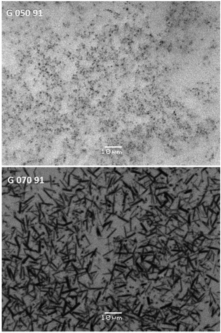 | ||
| Fig. 11 SEM images of the enamelled Cr1/3Zr2P3O12 sample (SG, 800 °C) within two types of glazes. | ||
At the last step, we have tested the colour stability of the enamelled samples at daylight. It is well known that sunlight causes the most damage such as discolouration or colour change to the coloured surfaces. The employed Q-Sun xenon test chamber can be used to simulate and accelerate service conditions and to test lightfastness of the pigments. The irradiation of the xenon lamp which is employed in this test provides the most realistic simulation of the full sunlight spectrum. The colour stability of the samples was tested for 1000 h. The total colour difference of the samples after sunlight irradiation can be calculated by several approaches.42,43 The most conventional difference can be presented as geometrical distance between the two positions in the CIELAB colour space: ΔEab* = (ΔL*2 + Δa*2 + Δb*2)0.5. A ΔEab* value of around 2.3 corresponds to a just noticeable difference (JND). The resulting colour difference can be split into component contributions, namely lightness (ΔL* = L1* − L2*), saturation (ΔCab* = (a1*2 + b1*2)0.5 − (a2*2 + b2*2)0.5) and hue (ΔHab* = (ΔEab*2 − ΔL*2 − ΔCab*2)0.5). Despite wide applications of these formulas due to their simplicity, the obtained differences are not always correctly reproduced when the system is applied to pigmented coating. The same concerns JND, whose value of 2.3 is quite approximate, and there are significant variations in a visual JND over colour space. For these reasons a new colour difference formula “CIE94” has been presented by CIE: ΔE94* = ((ΔL*/kLSL)2 + (ΔCab*/kCSC)2 + (ΔHab*/kHSH)2)0.5, where SL = 1, SC = 1 + 0.045ΔCab,1*, SH = 1 + 0.015ΔCab,1*.44 In the formula, the ki are the parameters of externally imposed conditions, such as conditions specific to a certain application or conditions different from the standard. This formula is used most widely in textile and graphic art applications, where special ki values have been developed in order to provide the best colour match. Generally, under the standard conditions, kL = kC = kH = 1 and these values are also satisfactory for most of the applications as well. As follows from the presented formulas, the correction terms of this approach are restricted to the chroma effect only. Another approach for the calculation of colour differences, namely the CMC system, which additionally takes into account the dependence on the hue angle, has been developed by CMC.45 The formula is stated as follows: ΔECMC = ((ΔL*/lSL)2 + (ΔCab*/cSC)2 + (ΔHab*/SH)2)0.5, where SL = 0.040975L1*/(1 + 0.01765L1*), if L1* ≥ 16, or SL = 0.511, if L1* < 16; SC = 0.0638Cab,1*/(1 + 0.0131Cab,1*) + 0.638; SH = (FT + 1 − F)SC with F = Cab,1*2/(Cab,1*4 + 1900)0.5 and T = 0.36 + |0.4cos(35° + hab,1°)|, if −15° ≤ hab,1° ≤ 164°, or T = 0.56 + |0.2cos(168° + hab,1°)|, if 164° ≤ hab,1° ≤ 345°. The factors c = l = 1 are generally acceptable as default parameters. The colour difference parameters between the non-irradiated and irradiated samples which were calculated according to the three described approaches are summarised in Table 4.
| Sample | ΔEab* | ΔL* | ΔCab* | ΔHab* | ΔE94* | ΔECMC |
|---|---|---|---|---|---|---|
| Glaze G 050 91 | 0.59 | −0.33 | 0.49 | 0.02 | 0.36 | 0.39 |
| Glaze G 070 91 | 0.52 | −0.36 | 0.35 | 0.10 | 0.36 | 0.40 |
Generally, the total colour difference for the glaze G 050 91 is higher than that for G 070 91. Detailed analysis of component contributions to the colour change (ΔL*, ΔCab* and ΔHab*) for both samples shows that the colour hue h° changed the least, while at the same time, the colour became lighter and less saturated after irradiation. Comparison of the calculated values shows that all three approaches provided very close results. Although the highest colour difference was provided by the CIELAB system, which does not account for the colour saturation and hue changes, the observed values are still very low and the colour change can be defined as imperceptible or just noticeable to the human eye. In conclusion, the Cr1/3Zr2P3O12 pigment can be considered as sunlight stable.
Conclusions
In the presented study we have hypothesised and confirmed the existence of a new chromium(III) phosphate in the NASICON family. The Cr1/3Zr2P3O12 phase can be obtained by the sol–gel method with employment of thermal processing at relatively low temperatures (around 800 °C). According to powder XRD analysis, Cr1/3Zr2P3O12 crystallises in the NASICON-related SW structure type, where chromium atoms occupy charge-compensating sites with a strongly distorted tetrahedral environment. The obtained phase can be considered as the first example of a phosphate compound containing chromium(III) in unusual tetrahedral coordination with oxygen, which is energetically very disadvantageous for its d3 electronic configuration. Increased constraints of such structural organisation result in low thermal stability and degradation of this phase above 800 °C leading to the formation of zirconium and chromium phosphates (ZrP2O7, Zr2(PO4)2O and Cr2P6O18).The single phase product of Cr1/3Zr2P3O12 has been characterised as a ceramic pigment. The sample provides saturated green colouration of glazes, which is stable to sunlight irradiation. The presented optical spectrum of this compound can be considered as the first example of such a spectrum characterising chromium(III) in a unique oxygen tetrahedral environment. The ceramic glaze with a lower content of fluxing agents provided a very low pigment–glaze interaction, which helped us to avoid the pigment dissolution and unfavourable crystallisation on the enamelled surface and, therefore, can be suggested as preferable for this application.
Acknowledgements
The Ministry of Education, Youth and Sports of the Czech Republic, project CZ.1.07/2.3.00/30.0021 “Enhancement of R&D Pools of Excellence at the University of Pardubice”, financially supported this work.Notes and references
- J. Alamo and R. Roy, J. Am. Ceram. Soc., 1984, 67, 78 CrossRef PubMed.
- T. Oota and I. Yamai, J. Am. Ceram. Soc., 1986, 69, 1 CrossRef CAS PubMed.
- C. N. R. Rao and J. Gopalakrishnan, New directions in Solid State Chemistry, Cambridge Univ. Press, Cambridge, 1986 Search PubMed.
- J. B. Goodenough, H. Y. P. Hong and J. A. Kafalas, Mater. Res. Bull., 1976, 11, 203 CrossRef CAS.
- B. E. Scheetz, D. K. Agrawal, E. Breval and R. Roy, Waste Manage., 1994, 14(6), 489 CrossRef CAS.
- I. Shchelokov, E. Asabina, M. Sukhanov, M. Ermilova, N. Orekhova and V. Pet'kov, et al. , Solid State Sci., 2008, 10, 513 CrossRef CAS PubMed.
- M. M. Ermilova, M. V. Sukhanova, R. S. Borisova, N. V. Orekhova, V. I. Pet'kov and S. A. Novikovac, et al. , Catal. Today, 2012, 193, 37 CrossRef CAS PubMed.
- S. Komarneni and W. W. Gould, The Penn State Research Foundation, assignee. United States patent, US 2000-177564P, 2000, Jan 21 Search PubMed.
- S. Komarneni and W. W. Gould, The Penn State Research Foundation, assignee. United States patent, US 006387832B1, 2002, May 14 Search PubMed.
- N. Gorodylova, V. Kosinová, Ž. Dohnalová, P. Bělina and P. Šulcová, Dyes Pigm., 2013, 98, 393 CrossRef CAS PubMed.
- L. Hagman and P. Kierkegaard, Acta Chem. Scand., 1968, 22, 1822 CrossRef CAS PubMed.
- A. I. Orlova, Czech J. Phys., 2003, 53, A649 CrossRef CAS.
- A. Jouanneaux, A. Verbaere, Y. Piffard, A. N. Fitch and M. Kinoshita, Eur. J. Solid State Inorg. Chem., 1991, 28, 683 CAS.
- V. I. Petkov, V. S. Kurazhkovskaya, A. I. Orlova and M. L. Spiridonova, Crystallogr. Rep., 2002, 47, 736 CrossRef CAS.
- F. J. Berry, N. Costantini and L. E. Smart, Solid State Ionics, 2006, 177, 2889 CrossRef CAS PubMed.
- M. C. Cuadrado and J. Alamo, Br. Ceram. Trans., 1988, 87, 141 CAS.
- R. S. Pavlov, V. B. Marza and J. B. Carda, J. Mater. Chem., 2002, 12, 2825 RSC.
- K. Byrappa, G. S. Gopalakrishna and A. B. Kulkarni, Indian J. Phys., 1987, 61A, 377 CAS.
- E. R. Losilla, S. Bruque, M. A. G. Aranda, L. M. Real and E. M. M. Quarton, Solid State Ionics, 1998, 11, 253 Search PubMed.
- M. Sugantha and U. V. Varadaraju, Solid State Ionics, 1997, 95, 201 CrossRef CAS.
- M. Barj, K. Chhor, L. Abello, C. Pommier and C. Delmas, Solid State Ionics, 1988, 28–30, 432 CrossRef.
- J. F. Bocquet, M. Barj, G. Lucazeau and G. Mariotto, Solid State Ionics, 1988, 28–30, 411 CrossRef.
- C. Delmas, J. C. Viala, R. Olazcuaga, G. Le Flem, P. Hagenmuller, F. Cherkaoui and R. Brochu, Solid State Ionics, 1981, 3/4, 209 CrossRef.
- A. Alami Talbi, R. Brochu, C. Parent, L. Rabardel and G. Le Flem, J. Solid State Chem., 1994, 110, 350 CrossRef.
- G. Buvaneswari and U. V. Varadaraju, Mater. Res. Bull., 2000, 35, 1313 CrossRef CAS.
- V. S. Kurazhkovskaya, D. M. Bykov, E. Yu. Borovikova, N. Yu. Boldyrev, L. Mikhalitsyn and A. I. Orlova, Vib. Spectrosc., 2010, 52, 137 CrossRef CAS PubMed.
- R. Shannon, Acta Crystallogr., Sect. A: Cryst. Phys., Diffr., Theor. Gen. Cryst., 1976, 32, 751 CrossRef.
- Y. Du, Z. X. Cheng, S. X. Dou and X. L. Wang, Mater. Lett., 2010, 64, 2251 CrossRef CAS PubMed.
- S. Singhal and K. Chandra, J. Solid State Chem., 2007, 180, 296 CrossRef CAS PubMed.
- A. Rais, A. M. Gismelseed and I. A. Al-Omari, Phys. Status Solidi, 2005, 242, 1497 CrossRef CAS PubMed.
- S. Ji, S.-H. Lee, C. Broholm, T. Y. Koo, W. Ratcliff, S. W. Cheong and P. Zschack, Phys. Rev. Lett., 2009, 103, 037201 CrossRef CAS.
- D. T. Sviridov and R. K. Sviridova, Zhurnal Prikladnoi Spektroskopii, 1981, 34, 663 CAS.
- J. Arsene, J. Lopitauz, M. Drifford and M. Lenglet, Phys. Status Solidi A, 1979, 52, K111 CrossRef CAS PubMed.
- http://wwwchem.uwimona.edu.jm/courses/CFSE.html .
- CIE, In Supplement No. 2 of CIE Publ. No. 15 (E1-1.31)1971. Paris: Bureau Central de la CIE, 1978.
- J. Rodriguez-Carvajal and T. Roisnel, Int. Union Crystallogr. Newletter, 1998, 20, 1 Search PubMed.
- A. Kazakos-Kijowski, S. Komarneni, D. Agrawal and R. Roy, Mater. Res. Bull., 1988, 23, 1177 CrossRef CAS.
- M. Barj, G. Lucazeau and C. Delmas, J. Solid State Chem., 1992, 100, 141 CrossRef CAS.
- H. Szymczak, M. Wardzynska and I. E. Mylnikova, J. Phys. C: Solid State Phys., 1975, 8, 3937 CrossRef CAS.
- N. Gorodylova, Ž. Dohnalová, P. Koštál, P. Šulcová and M. Vlček, J. Therm. Anal. Calorim., 2014, 100, 605 CrossRef.
- K. Nomura, Private Commun., 1993.
- G. Buxbaum and G. Pfaff, Industrial Inorganic Pigments, Wiley-VCH, Weinheim, 2005 Search PubMed.
- H. G. Völz, Industrial Colour Testing. Fundamentals and Techniques, Wiley-VCH, Weinheim, 2001 Search PubMed.
- CIE, Technical Report 116, 1995, p. 1.
- CMC, British Standard BS 6923, 1988.
| This journal is © The Royal Society of Chemistry 2014 |