 Open Access Article
Creative Commons Attribution 3.0 Unported Licence
Fabrication of N-doped TiO2 coatings on nanoporous Si nanopillar arrays through biomimetic layer by layer mineralization
Yong
Yan
,
Dong
Wang
* and
Peter
Schaaf
TU Ilmenau, Institute of Materials Engineering and Institute of Micro- and Nanotechnologies MarcoNano, Chair Materials for Electronics, Gustav-Kirchhoff-Str. 5, 98693 Ilmenau, Germany. E-mail: dong.wang@tu-ilmenau.de; peter.schaaf@tu-ilmenau.de
First published on 27th March 2014
Abstract
Si/N-doped TiO2 core/shell nanopillar arrays with a nanoporous structure are fabricated through a simple protein-mediated TiO2 deposition process. The Si nanopillar arrays are used as templates and alternatively immersed in aqueous solutions of catalytic molecules (protamine, PA) and the titania precursor (titanium(IV) bis(ammonium lactato)dihydroxide, Ti-BALDH) for the layer by layer mineralization of a PA/TiO2 coating. After a subsequent calcination, a N-doped TiO2 layer is formed, and its thickness could be controlled by varying the cycles of deposition. Moreover, the nanoporous structure of the Si nanopillars strongly affects the formation of the TiO2 layer. The obtained Si/TiO2 nanocomposites show significantly improved solar absorption compared with commercially purchased TiO2 nanoparticles.
1. Introduction
Titania (TiO2) has attracted much attention due to its unique properties and many promising applications in environmental and energy areas ranging from photocatalysis and solar cells to lithium ion batteries.1 However, the limited solar absorption and electrochemical activity caused by its poor electric conductivity and large bandgap is substantially lower than practically required.2,3 For improving the electric conductivity of TiO2, its combination with conducting agents, such as metals, metal oxides, and carbonaceous materials, has proved to be a common strategy to enhance electron transport;4 on the other hand, fabrication of TiO2 with a specific morphology (e.g. a high-aspect-ratio or nanoporous structure) is a promising pathway to modify the separation and transportation of charge carriers in TiO2.5 For improving the solar adsorption of TiO2, N-doping and sensitization with low bandgap semiconductors are considered effective routes, which could improve the photocatalytic activity of TiO2 by increasing its optical absorption coefficient and wavelength range.6–8As a low bandgap semiconductor, silicon (Si, Eg = 1.12 eV) can adsorb sunlight efficiently, and furthermore, highly doped Si has excellent conductivity (ρ < 0.005 Ω cm). However, it is difficult to simply use Si in photo- or electrochemical applications due to its high valence band maximum energy and poor chemical stability in electrolytes.9 Therefore, a composite structure, Si coated with a stable semiconductor (e.g. TiO2), has been proposed to compensate these shortcomings.10 Nevertheless, the synthesis of nanostructured TiO2 with N-doping normally requires harsh conditions (NH3 atmosphere, acids and bases, or organic solvents), which will degrade the material properties of Si.6 Therefore, N-doping, morphology modification, and sensitization of TiO2 with Si are not easy to achieve simultaneously, and investigations of synergistic effects of them are limited. Hence, devising a process for preparing N-doped TiO2 with controlled morphology under relatively mild conditions is desirable.
Inspired by natural mineralization mechanisms, biomimetic mineralization has been recognized to offer an environmentally benign and energy efficient route for TiO2 synthesis.11 In this process, using peptides or its derivatives as catalytic molecules, micro- and nanostructured TiO2 will be obtained under mild conditions.12,13 Additionally, the morphology of the product could be controlled by the use of different templates such as CaCO3 microparticles,14 3D diatom frustules,15 anodized aluminum oxide templates,16 silica spheres,17 N-doped carbon nanotubes,18 silk fibers,19 peptide nanofibers,20 graphene nanosheets,21 and nickel foam.22 Moreover, a recently-developed layer by layer mineralization process provides a versatile method for the formation of multilayer peptide/TiO2 hybrid materials on templates;14–17,21,22 and some studies have demonstrated that N-doped TiO2 could be synthesized easily by sintering of peptide/TiO2 composites.20
In this work, nanoporous Si nanopillar arrays fabricated by a combination of nanoimprint lithography and metal-assisted chemical etching are used as templates,23 and are alternatively immersed in aqueous protamine (PA) and titanium bis(ammonium lactato)-dihydroxide (Ti-BALDH) solution: positively charged protamine molecules are adsorbed on the Si nanopillars through a capillary effect and electrostatic attraction, and subsequently induce the hydrolysis and condensation of Ti-BALDH to form the negatively charged TiO2, which enables layer by layer (LBL) deposition of protamine/TiO2 hybrid materials on the surface of the Si nanopillars. After calcination, Si/N-doped TiO2 core/shell nanopillar arrays with a nanoporous structure are obtained, which shows significantly improved solar absorption. Moreover, the thickness of the N-doped TiO2 layer could be controlled by varying the cycles of deposition. The obtained Si/TiO2 core/shell nanopillars might have potential applications in photocatalysis, and this study may pave the way for further controlled synthesis of Si/TiO2 nanocomposites through biomimetic mineralization.
2. Experimental section
2.1. Fabrication of nanoporous Si nanopillar arrays
Ordered arrays of nanoporous Si nanopillars with hexagonal symmetry were fabricated from (100) oriented and highly doped p type Si wafer (B-doped, ρ < 0.005 Ω cm) using a combination of substrate conformal imprint lithography (SCIL)24 and metal-assisted chemical etching (MaCE).25 A 20 nm Au film was deposited as a catalyst for the MaCE and the fabrication process is well described in our previous work.23,26 The Au film was removed using a solution of KI and I2 and the samples were dried with N2 gas.2.2. Materials and synthesis
Protamine sulfate salt from salmon (PA) was purchased from Sigma-Aldrich and used without purification. Titanium(IV) bis(ammonium lactato) dihydroxide (Ti-BALDH) aqueous solution was purchased from Alfa Aesar. 0.10 g protamine sulfate salt was added to 20 ml of pure H2O and the catalytic molecular solution was obtained. Similarly, 0.98 g Ti-BALDH (50 wt% aqueous solution) was dissolved in 20 ml of H2O and a transparent titania precursor solution (pH = 6.23) was prepared. The biomimetic layer by layer (LBL) titania deposition approach to prepare Si/N-doped TiO2 core/shell nanopillar arrays is schematically illustrated in Scheme 1.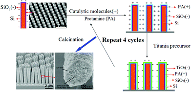 | ||
| Scheme 1 Schematic illustration of the biomimetic layer-by-layer (LBL) TiO2 mineralization on nanoporous Si nanopillar arrays. | ||
Nanoporous Si nanopillar arrays (size: 1.0 cm × 1.0 cm) were used as templates, and firstly immersed in catalytic molecular solution (PA 5 wt‰) at room temperature for 30 min. Through capillary effects and electrostatic interactions, the positively charged PA was adsorbed on the surface of Si. After that, the Si nanopillar arrays were removed from the PA solution and rinsed with deionized water. Next, the Si nanopillar arrays with adsorbed PA were immersed in titania precursor solution at room temperature also for 30 min, and induced the hydrolysis and condensation of Ti-BALDH to form the negatively charged TiO2 layer. After being removed from the Ti-BALDH solution and washed with deionized water, PA/TiO2 coated Si nanopillars were obtained. By repeating the above steps for several cycles, the thickness of the PA/TiO2 layer was stepwise increased. After calcination of these samples in Ar at 500 °C for 3 h, nitrogen atoms of the protamine were introduced into the TiO2 structure as doped element, and Si/N-doped TiO2 core/shell nanopillar arrays with a nanoporous structure were obtained.
2.3. Characterization
X-ray diffraction (XRD) patterns of the samples were recorded on a SIEMENS/BRUKER D5000 X-ray diffractometer using Cu-Kα radiation at 40 kV and 40 mA, with the samples being scanned from 2θ = 10°–90° at a rate of 0.02° s−1 in a Bragg–Brentano geometry. Scanning electron microscopy (SEM) images were taken with a Hitachi S-4800 instrument, where energy-dispersive X-ray spectrometry (EDS) was also carried out. The optical absorption in the wavelength range from UV to the visible was measured using a diffuse reflectance accessory of a UV-vis spectrometer (Cary 35 5000 UV-Vis-NIR). Zeta potentials of the samples were obtained from a Malvern Zetasizer Nano ZS. The X-ray photoelectron spectroscopy (XPS) analysis was performed using a spectrometer (Kratos Axis Ultra XPS) with monochromatized Al-Kα radiation and an energy resolution of 0.48 eV.3. Results and discussion
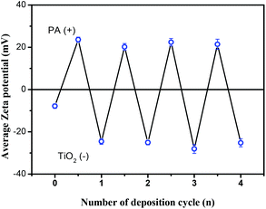
The method of protamine-mediated layer by layer titania mineralization is based on previously reported studies.14–17,21,22 Protamine (PA) is a kind of cationic protein extracted from sperm nuclei, which can induce the formation of a titania/protamine nanocomposite from a water-stable titania precursor (Ti-BALDH).14 In the presented experiment, the nanoporous Si nanopillar arrays used as a template have a negatively charged surface due to the existence of Si–O-bearing layer (∼1 nm) when it was exposed to air for several minutes.23 This template is alternatively immersed in aqueous solutions of catalytic molecules (PA) and the titania precursor (Ti-BALDH) for the layer-by-layer fabrication of PA/TiO2 coating (Scheme 1).The polycationic PA molecules bind to the negatively charged Si surface and induce the formation of a TiO2 layer from the Ti-BALDH precursor. This ability of PA to bind to the Si as well as to the TiO2 surface enabled the layer-by-layer (LBL) fabrication of PA/TiO2 nanocomposite coating on the Si nanopillars. Zeta potential analysis was used to characterize the surface charge of Si nanopillars at every step during the first four cycles of this LBL TiO2 deposition process; an oscillation for zeta potential measurement after each alternative deposition of the PA and TiO2 was observed (Fig. 1), which is consistent with the presence of positively charged PA molecules or of negatively charged TiO2, respectively.
In order to remove the adsorbed water, to pyrolyze the organic molecules, and to crystallize the TiO2, the PA/TiO2 coated Si nanopillars are calcinated at 500 °C in Ar for 3 h. Fig. 2 shows the XRD patterns of PA/TiO2 coated Si nanopillars before and after calcination. The original TiO2 on Si nanopillars displays an amorphous structure, and no peaks are observed between 20° and 60°, while it shows four peaks at 2θ = 25.3°, 33.1°, 37.8°, and 48.1° after calcination, which demonstrates the formation of the anatase phase. The calculated average crystallite size (using the Scherrer formula) of TiO2 in the (101) direction is 6 nm.
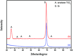 | ||
| Fig. 2 XRD patterns of the PA/TiO2 coated Si nanopillars via exposure to 4 LBL deposition cycles before (a) and after calcination (b). | ||
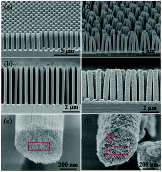
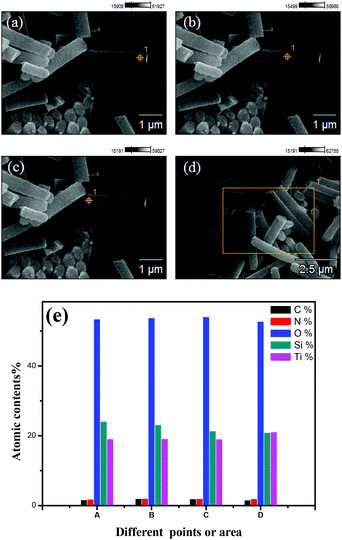
Fig. 3a and b show an overview SEM image of the fabricated nanoporous Si nanopillars. The distance between two adjacent pillars (periodicity) is 1.0 μm, and the pillar height is about 5.2 μm; moreover, the pillars are elliptical with major and minor diameters of 613 nm and 385 nm, respectively. Fig. 3c shows the magnified images of the cross-section of the pillars, which demonstrated the existence of a three dimensional porous structure, and its pore size is about 10 nm. Fig. 3d–f show the TiO2 coated Si nanopillars via exposure to 4 deposition cycles after calcination. A uniform TiO2 coating with a thickness of 45 nm–55 nm was observed on the surface of the Si pillars, which were comprised of numerous tiny nanoparticles (<10 nm). In addition, the pore size in the bulk of Si pillars was obviously decreased, due to the filling of TiO2 (Fig. 3f). Interestingly, more TiO2 was filled close to the surface rather than in the center of the nanoporous pillars. An explanation for this might be that the initial deposition of TiO2 at the surface hindered the further diffusion of PA and Ti-BALDH into the center of the pillars, leading to the lower deposition amount in the center. EDS element mapping of the TiO2 coated Si nanopillars exhibits the presence of Ti, O, Si, N, and C species (Fig. 4). The existence of N and C species is derived from the organic pyrolysis during calcination. The XPS N 1s spectrum of this sample showed two nitrogen features: the peak with a higher binding energy centered at 401.4 eV can be assigned to nitrogen in the form of a Ti–N–O linkage,27 and the peak with a lower binding energy located at 397.4 eV can be attributed to the nitrogen atom replacing the oxygen atoms in the TiO2 crystal lattice with the formation of an N–Ti–N bond (Fig. 5).28 These results demonstrate that nitrogen atoms of the protamine are introduced into the TiO2 structure as the doped element, and the decomposition of its molecular chains forms small amounts of amorphous carbon in the TiO2.20 It should be noted that the distribution of Ti is wider than that of Si, indicating the structure of the Si core and TiO2 shell. Fig. 6 exhibits the EDS spectrum of this sample, and a quantitative calculation demonstrates that the atomic ratio of Ti/Si is close to 1 for both points and area analysis, indicating that the TiO2 deposition through biomimetic LBL mineralization is uniform. However, the content of Ti slightly increases from position A to C (from bottom to top) for TiO2 coated Si nanopillars. This result might be induced by the lower concentration of PA and Ti-BALDH in the bottom of the Si pillars, because the PA and Ti-BALDH molecules will be partially consumed by the adsorption or reaction in the diffusion process from the top to the bottom.
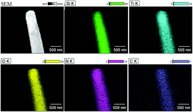 | ||
| Fig. 4 EDS element mapping images of the TiO2 coated Si nanopillars via exposure to 4 LBL deposition cycles after calcination (as shown in Fig. 3). | ||
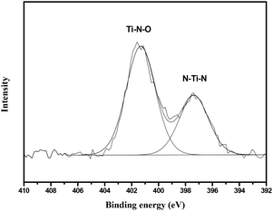 | ||
| Fig. 5 N 1s XPS spectra of the TiO2 coated Si nanopillars via exposure to 4 LBL deposition cycles after calcination. | ||
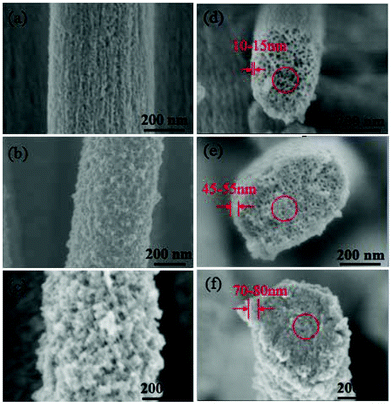
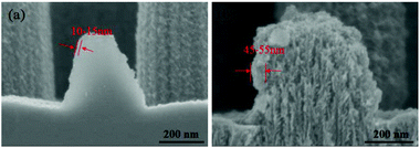
To allow a deeper understanding of the formation of the TiO2 coating, Si nanopillars coated with different cycles of deposition after calcination are characterized. After 1 cycle of deposition, a TiO2 shell with a thickness of 10–15 nm is formed, and the porous structure on the surface of the nanopillars still remains. The filling of the porous pillar interiors is limited as the pore size in the cross-section is similar as initially (Fig. 7a and d). After 4 cycles of deposition, the thickness of the TiO2 shell is increased to 45–55 nm, and the porous structure on the surface of the nanopillars was almost fully covered by TiO2 layers. Moreover, TiO2 also clearly exists in the center of the nanopillars with decreasing pore size in the cross-section (Fig. 7b and e). The thickness of the TiO2 shell is further increased to 70–80 nm after 8 cycles of deposition, and the surface of the nanopillars becomes very rough with the appearance of numerous TiO2 nanoparticles; in addition, the interior of the pillars seems to be completely filled with TiO2 (Fig. 7c and f).
Compared with other reports, it is observed that biomimetic LBL TiO2 deposition on nanoporous Si nanopillars is more efficient than that of other templates.22–26 The ability of the catalytic molecules to bind to both the templates and the TiO2 through electrostatic attraction is considered the key factor for this process. The experimental results indicate that the porous structure of the used Si nanopillars also strongly affects the formation of the TiO2 layer. For comparison, solid Si nanopillars (no pores)23 are used in an identical TiO2 deposition process. The thickness of the formed TiO2 shell is only 10–15 nm after 4 cycles, which is much thinner than that of nanoporous Si nanopillars (Fig. 8). One explanation might be that the nanoporous structure can enhance the adsorption of PA and Ti-BALDH through the much higher surface area and capillary effects, which induce more TiO2 formation in both the surface and the interiors of the Si nanopillars.
Fig. 9 shows the UV-vis absorption spectra of purchased TiO2 nanoparticles (Degussa P25) in comparison with the presented TiO2 coated Si nanopillars (4 LBL deposition cycles after calcination). P25 shows a steep increase in absorption at wavelengths of 400 nm due to the intrinsic bandgap of crystalline anatase TiO2. Compared with P25, the TiO2 coated Si nanopillars show a significantly enhanced absorption in the region of visible light, which can be attributed to the synergistic effect between N doping and Si sensitization.
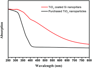 | ||
| Fig. 9 UV-vis absorption spectra of purchased TiO2 nanoparticles (Degussa P25) and TiO2 coated Si nanopillars via exposure to 4 LBL deposition cycles after calcination. | ||
4. Conclusions
In summary, Si/N-doped TiO2 core/shell nanopillar arrays with a nanoporous structure are produced through a protamine-mediated layer-by-layer TiO2 mineralization. The thickness of the N-doped TiO2 layer can be controlled by varying the cycles of deposition, and the experimental results demonstrate that the nanoporous structure of the Si nanopillars strongly affects and enhances the formation of the TiO2 layer. The obtained Si/TiO2 nanocomposites show significantly improved solar adsorption. As a consequence, the obtained Si/TiO2 core/shell nanopillars might have potential applications in photocatalysis. This study may pave the way for further controlled synthesis of Si/TiO2 nanocomposites through biomimetic mineralization.Acknowledgements
The authors are grateful to Dr Ran Ji from SUSS MicroTec Lithography GmbH (Munich) for performing the substrate conformal imprint lithography (SCIL). They also acknowledge Mrs Manuela Breiter, Mrs Birgitt Hartmann, Mrs Ilona Marquardt, and Mr Joachim Döll from TU Ilmenau for their help with sample preparation, and Mrs Magali Camargo for her help in zeta-potential measurements. This work was partially supported by a grant (NanoBatt TNA VII-1/2012) from the state of Thuringia (TMWAT by LEG Thüringen) and co-financed by the European Union within the frame of the European Funds for Regional Development (EFRD). Yong Yan is supported by means of a doctoral scholarship from the Carl Zeiss Stiftung (Germany).Notes and references
- X. B. Chen and S. S. Mao, Chem. Rev., 2007, 107, 2891 CrossRef CAS PubMed
.
- Y. Yan, B. Hao, D. Wang, G. Chen, E. Markweg, A. Albrecht and P. Schaaf, J. Mater. Chem. A, 2013, 1, 14507 CAS
.
- X. Lu, G. Wang, T. Zhai, M. Yu, J. Gan, Y. Tong and Y. Li, Nano Lett., 2012, 12, 1690 CrossRef CAS PubMed
.
- X. Xin, X. F. Zhou, J. H. Wu, X. Y. Yao and Z. P. Liu, ACS Nano, 2012, 6, 11035 CrossRef CAS PubMed
.
- Z. Zheng, B. Huang, J. Lu, Z. Wang, X. Qin, X. Zhang, Y. Dai and M. H. Whangbo, Chem. Commun., 2012, 48, 5733 RSC
.
- R. Asahi, T. Morikawa, T. Ohwaki, K. Aoki and Y. Taga, Science, 2001, 293, 269 CrossRef CAS PubMed
.
- Y. L. Lee, C. F. Chi and S. Y. Liau, Chem. Mater., 2010, 22, 922 CrossRef CAS
.
- J. Hensel, G. M. Wang, Y. Li and J. Z. Zhang, Nano Lett., 2010, 10, 478 CrossRef CAS PubMed
.
- Y. J. Hwang, A. Boukai and P. D. Yang, Nano Lett., 2009, 9, 410 CrossRef CAS PubMed
.
- Y. W. Chen, J. D. Prange, S. Dühnen, Y. Park, M. Gunji, C. E. Chidsey and P. C. McIntyre, Nat. Mater., 2011, 10, 539 CrossRef CAS PubMed
.
- J. L. Sumerel, W. Yang, D. Kisailus, J. C. Weaver, J. H. Choi and D. E. Morse, Chem. Mater., 2003, 15, 4804 CrossRef CAS
.
- G. P. Smith, K. J. Baustian, C. J. Ackerson and D. L. Feldheim, J. Mater. Chem., 2009, 19, 8299 RSC
.
- S. L. Sewell and D. W. Wright, Chem. Mater., 2006, 18, 3108 CrossRef CAS
.
- Y. J. Jiang, D. Yang, L. Zhang, Q. Y. Sun, X. H. Sun, J. Li and Z. Y. Jiang, Adv. Funct. Mater., 2009, 19, 150 CrossRef CAS
.
- Y. N. Fang, Q. Z. Wu, M. B. Dickerson, Y. Cai, S. Shian, J. D. Berrigan, N. Poulsen, N. Kroger and K. H. Sandhage, Chem. Mater., 2009, 21, 5704 CrossRef CAS
.
- J. D. Berrigan, T. S. Kang, Y. Cai, J. R. Deneault, M. F. Durstock and K. H. Sandhage, Adv. Funct. Mater., 2011, 21, 1693 CrossRef CAS
.
- N. R. Haase, S. Shian, K. H. Sandhage and N. Kroger, Adv. Funct. Mater., 2011, 21, 4243 CrossRef CAS
.
- W. J. Lee, J. M. Lee, S. T. Kochuveedu, T. H. Han, H. Y. Jeong, M. Park, J. M. Yun, J. Kwon, K. No, D. H. Kim and S. O. Kim, ACS Nano, 2012, 6, 935 CrossRef CAS PubMed
.
- M. B. Dickerson, C. L. Knight, M. K. Gupta, H. R. Luckarift, L. F. Drummy, M. L. Jespersen, G. R. Johnson and R. R. Naik, Mater. Sci. Eng., C, 2011, 31, 1748 CrossRef CAS PubMed
.
- T. Nonoyama, T. Kinoshita, M. Higuchi, K. Nagata, M. Tanaka, K. Sato and K. Kato, J. Am. Chem. Soc., 2012, 134, 8841 CrossRef CAS PubMed
.
- B. Hao, Y. Yan, X. B. Wang and G. Chen, ACS Appl. Mater. Interfaces, 2013, 5, 6285 CAS
.
- X. B. Wang, Y. Yan, B. Hao and G. Chen, ACS Appl. Mater. Interfaces, 2013, 5, 3631 CAS
.
- D. Wang, R. Ji, S. Du, A. Albrecht and P. Schaaf, Nanoscale Res. Lett., 2013, 8, 42 CrossRef PubMed
.
- R. Ji, M. Hornung, M. A. Verschuuren, R. van de Laar, J. van Eekelen, U. Plachetka, M. Moeller and C. Moormann, Microelectron. Eng., 2010, 87, 963 CrossRef CAS PubMed
.
- X. Li and P. W. Bohn, Appl. Phys. Lett., 2000, 77, 2572 CrossRef PubMed
.
- D. Wang, S. Schönherr, R. Ji, A. Herz, C. Ronning and P. Schaaf, J. Micromech. Microeng., 2013, 23, 074004 CrossRef
.
- J. Wang, W. Zhu, Y. Zhang and S. Liu, J. Phys. Chem. C, 2007, 111, 1010 CAS
.
- G. Yang, Z. Jiang, H. Shi, T. Xiao and Z. Yan, J. Mater. Chem., 2010, 20, 5301 RSC
.
| This journal is © The Royal Society of Chemistry 2014 |

