 Open Access Article
Creative Commons Attribution 3.0 Unported Licence
Mechanism of CO2 hydrogenation to formates by homogeneous Ru-PNP pincer catalyst: from a theoretical description to performance optimization†
Georgy A.
Filonenko
ab,
Emiel J. M.
Hensen
ab and
Evgeny A.
Pidko
*ab
aInorganic Materials Chemistry, Department of Chemical Engineering, Eindhoven University of Technology, P.O. Box 513, 5600 MB Eindhoven, The Netherlands. E-mail: e.a.pidko@tue.nl
bInstitute for Complex Molecular Systems, Eindhoven University of Technology, P.O. Box 513, 5600 MB Eindhoven, The Netherlands
First published on 3rd June 2014
Abstract
The reaction mechanism of CO2 hydrogenation by pyridine-based Ru-PNP catalyst in the presence of DBU base promoter was studied by means of density functional theory calculations. Three alternative reaction channels promoted by the complexes potentially present under the reaction conditions, namely the dearomatized complex 2 and the products of cooperative CO2 (3) and H2 (4) addition, were analysed. It is shown that the bis-hydrido Ru-PNP complex 4 provides the unique lowest-energy reaction path involving a direct effectively barrierless hydrogenolysis of the polarized complex 5*. The reaction rate in this case is controlled by the CO2 activation by Ru–H that proceeds with a very low barrier of ca. 20 kJ mol−1. The catalytic reaction can be hampered by the formation of a stable formato-complex 5. In this case, the rate is controlled by the H2 insertion into the Ru–OCHO coordination bond, for which a barrier of 65 kJ mol−1 is predicted. The DFT calculations suggest that the preference for the particular route can be controlled by varying the partial pressure of H2 in the reaction mixture. Under H2-rich conditions, the former more facile catalytic path should be preferred. Dedicated kinetic experiments verify these theoretical predictions. The apparent activation energies measured at different H2/CO2 molar ratios are in a perfect agreement with the calculated values. Ru-PNP is a highly active CO2 hydrogenation catalyst allowing reaching turnover frequencies in the order of 106 h−1 at elevated temperatures. Moreover, a minor temperature dependency of the reaction rate attainable in excess H2 points to the possibility of efficient CO2 hydrogenation at near-ambient temperatures.
Introduction
Utilization of CO2 as a renewable C1 building block in chemical synthesis is recognized as a key strategy for developing more sustainable chemical technologies.1–4 Considerable attention has been devoted to CO2 coupling reactions for the production of cyclic carbonates or carboxylic acid derivatives.5–10 Alternatively, CO2 can be hydrogenated to C1 chemicals, such as formic acid (FA)11,12 and, more challenging, methanol.13–15 In addition to being important chemical intermediates, these compounds can be utilized as hydrogen storage agents as long as the reverse dehydrogenation reaction can be made to produce only carbon dioxide as the byproduct.16–20 Fully reversible processes for H2 storage/release have so far only been demonstrated for the CO2/FA pair.18–24The hydrogenation of carbon dioxide to formates has been the subject of many experimental and theoretical studies. The main focus has been on homogeneous catalysts, some of them with very high activity for the formation of formates and also their decomposition.25–29 Most of the homogeneous systems make use of noble metals,30,31 although a substantial progress has recently been made using first-row transition metal, namely, Fe32,33 and Co,34 complexes. Despite the apparent simplicity of the overall reaction, the mechanism of the catalytic CO2 hydrogenation by homogeneous catalysts is still under debate. One of the first examples of an active catalyst for CO2 hydrogenation under supercritical conditions, [Ru(H)2(PMe3)3],35 has been studied computationally by Sakaki and co-workers.36,37 The authors identified CO2 insertion into the Ru–H bond as the rate determining step (RDS) under water free conditions, whilst the coordination of H2 to Ru–formate species was shown to determine the reaction rate in the presence of water. A subsequent detailed investigation by Urakawa et al. revealed that CO2 insertion is a facile process, whereas the H2 insertion in the Ru–formate complex represents the rate determining step for [Ru(dmpe)2H2]-catalysed CO2 hydrogenation.38 These findings were used to rationalize the increased activity at elevated H2 partial pressure, which represented a major inconsistency with the earlier proposal on the RDS nature of the CO2 insertion step.
Substantial progress in the catalytic CO2 hydrogenation was made when Ir-PNP pincer complexes were introduced as catalysts by Nozaki39 and co-workers in 2009. The presence of a non-innocent PNP pincer ligand, which can be directly involved in chemical transformations in the course of the catalytic reaction,40–42 increases the complexity with respect to the mechanistic analysis. In the presence of a base, the PNP ligands can be deprotonated resulting in formation of a basic cooperative site on the side-arm of the dearomatized PNP* ligand that can participate in substrate activation40,41 (see Scheme 1 for a related reaction for Ru-PNP complex, 1 → 2). As a result, two alternative pathways were proposed for the hydrogenation of CO2 over Ir-PNP,43 the first of which involves the deprotonative ligand dearomatization as the key reaction step. The alternative mechanism involves the OH−-assisted hydrogen cleavage in the H2 σ-complex, which regenerates the initial state of the catalyst, as the RDS. The latter mechanism was supported in a theoretical study by Yang44 and Ahlquist45 who found that the direct base-assisted H2 cleavage was more favourable than pathways involving the ligand participation. A similar conclusion was drawn for iron- and cobalt-based PNP catalysts.
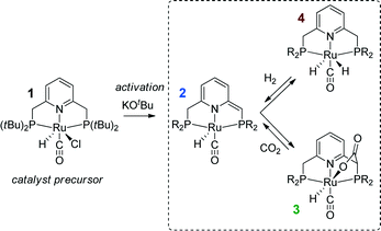 | ||
| Scheme 1 Activation of a Ru-PNP precursor 1 by deprotonation with a strong base and the subsequent metal–ligand cooperative activation of CO2 and H2. | ||
Recently, the application of ruthenium pincer catalysts in CO2 hydrogenation has been described.46,47 The corresponding ruthenium pincer complexes bearing pyridine-based PNN and PNP ligands are known to reversibly bind CO248,49via a metal–ligand cooperative mechanism (2 → 3, Scheme 1). The resulting products of [1,3]-CO2 addition can contribute to the overall performance of these catalysts in the hydrogenation reaction. Huff and Sanford46 reported that Ru-PNN pincer50 catalyst can be used for hydrogenation of CO2 to formates with a rate (turnover frequency, TOF) of 2200 h−1. A mechanism involving the dearomatization of the PNN ligand has been proposed. This proposal was confirmed in reactivity studies, employing KOtBu to liberate HCOO− at the end of the catalytic cycle. However, the possibility of ligand deprotonation with catalytically superior K2CO3 base has not been confirmed yet.
Previously, we have demonstrated that a related Ru-PNP catalyst 1 (ref. 50) (Scheme 1) shows remarkable catalytic performance in reversible CO2 hydrogenation.22,47 In a previous communication,47 we investigated the mechanism of the catalytic reaction by a combination of kinetic experiments and in situ NMR experiments supported by DFT calculations. The results pointed to the inhibiting effect of the CO2 adduct 3 on catalytic performance. In agreement with previous reports,38,43,44 bis-hydrido Ru species were postulated as the active state. It was argued that the dearomatized Ru-PNP* complex 2 did not contribute to the catalytic reaction. Nevertheless, the contribution of multiple reaction paths involving different species (Scheme 2) cannot be omitted and careful mechanistic analysis is required.
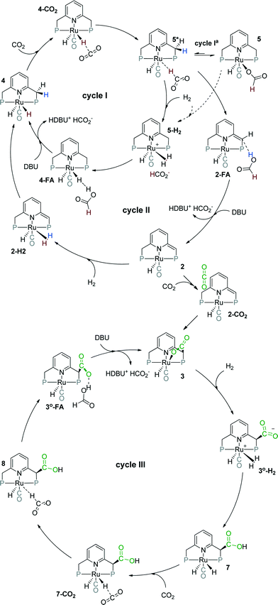 | ||
| Scheme 2 Possible catalytic cycles for CO2 hydrogenation to formates by Ru-PNP pincer complexes (tBu substituents of the ligand are omitted for clarity). | ||
Herein, we present a systematic DFT study of the CO2 hydrogenation to formates by Ru-PNP complexes that can be formed under reaction conditions. The catalytic cycles over the bis-hydrido complex 4, the dearomatized species 2 and the CO2-adduct 3 were considered (Scheme 2). This work is a continuation of our previous mechanistic study.47 The main focus will be on the analysis of the reaction networks underlying the catalytic process to identify the catalytic role of different intermediates present in the reaction mixture. The theoretical insights are validated by dedicated experiments.
Computational and experimental details
Density functional theory calculations
Similar to our previous work,47 density functional theory (DFT) calculations were performed with the PBE0 (also denoted as PBE1PBE and PBEh)51 hybrid exchange-correlation functional using Gaussian 09, revision D.01 program.52 The high accuracy of this method has been demonstrated by previous benchmark studies on a wide set of different chemical systems53,54 and by our own accuracy tests employing different DFT methods for modelling CO2 hydrogenation to formic acid.47 The full electron 6-311G(d,p) basis set55,56 was used for all atoms except ruthenium, for which the LanL2DZ basis set57,58 was employed. The polarisable continuum model (PCM) with standard parameters for THF and DMF solvents, as implemented in the Gaussian 09 rev. D.01 program package, was used during the geometry optimization and frequency analysis to account for bulk solvent effects. Because the differences in reaction free energies computed with PCM model of THF and DMF solvents do not exceed 5 kJ mol−1 (see ESI†), only the results obtained for the THF solvent are discussed here. The accuracy of this computational method was tested by calculating energetics of selected elementary reaction steps (2 + H2 → 4 (ref. 47) and 4 + CO2 → 5*, Scheme 1) using a larger triple-zeta + polarization quality basis set combination employing Def2-TZVPP59 basis set for the Ru centre and 6-311+G(d,p) for the light atoms. The resulting reaction and activation energies agreed within 5 kJ mol−1 with those obtained using the standard methodology (see ESI† and ref. 47). Note that the expansion of the basis set with diffuse functions has a negligible effect on the computed energetics, while it resulted in a much slower SCF convergence (when PCM model was used to account for solvent effects).The nature of the stationary points was evaluated from the analytically computed harmonic modes. No imaginary frequencies were found for the optimized structures, confirming that these correspond to local minima on the potential energy surface. All transition states exhibited a single imaginary frequency, corresponding to the eigenvector along the reaction path. The assignment of the transition state structure to a particular reaction path was tested by perturbing the structure along the reaction path eigenvector in the directions of the product and the reagent followed by geometry optimization. For catalytic cycles I, II and III starting from the activated species 3°–H2 IRC calculations were performed to additionally confirm the assignment of the transition states. The reaction (ΔE) and activation energies (E‡) reported in the manuscript were corrected for zero point (EZPE) energy contribution computed using the results of the normal-mode analysis. Free energy values (ΔG°) were computed using the results of the normal-mode analysis within the ideal gas approximation at a pressure of 1 atm and temperatures of 298 K.
Catalytic CO2 hydrogenation
All manipulations unless otherwise stated were performed using Schlenk techniques. Argon was dried with a Sicapent column. Air sensitive compounds were stored in a MBraun glovebox under an atmosphere of dry nitrogen or argon. Solvents were dispensed from MBraun solvent purification system. 1,8-Diazabicyclo[5.4.0]undec-7-ene (DBU) was purchased from Fluorochem and vacuum distilled from calcium hydride. Catalyst 1 was prepared according to original literature procedure.60Small scale CO2 hydrogenation experiments were performed in A96 parallel reactor at 70 °C under 40 bar of equimolar H2–CO2 mixture. In a typical experiment 3 mL THF or DMF, and appropriate amount of base DBU (3.3 mmol) or KOtBu (0.33 mmol) were mixed with 0.1 μmol of catalyst. The reaction was quenched after 2 hours by addition of water–ethanol mixture and immediately analyzed. Concentrations of formic acid were analyzed using Shimatzu HPLC setup with 25 mM phosphate buffer of pH = 2 as mobile phase using Prevail Organic Acid column. GC measurements, where appropriate, were performed using Shimatzu GC-17A instrument.
Kinetic measurements were carried out in Top Industrie 100 mL stainless steel autoclave. The vessel was evacuated overnight at 150 °C, purged several times with Ar, and the reaction medium was introduced by cannulae transfer. The autoclave was flushed with H2–CO2 mixture or hydrogen, preheated to reaction temperature and filled with H2–CO2 mixture up to operating pressure of 40 bar. The catalyst was then introduced via a dosage device and the reaction started. Constant pressure was maintained by a compensation device fitted with Bronkhorst EL-FLOW MFC unit and digital pressure meter with equimolar H2–CO2 mixture. Samples were withdrawn via dip-tube installation (dead volume 4 μL, sampling volume 110 μL), diluted to 1 mL and immediately analysed by HPLC and GC-FID. In a typical experiment 30 mL solvent, 5 mL DBU (33.4 mmol), 1 mL toluene or THF (used as an internal standard) and appropriate amount of catalysts dispensed from the stock solution were used. The kinetic traces represent single run results.
Results and discussion
Catalyst activation
Hydrogenation activity of Ru-PNP pincer is usually initiated by reacting a catalyst precursor 1 with a strong base to form a dearomatized Ru-PNP* species 2 (Scheme 1). Both substrates of the catalytic CO2 hydrogenation reaction, namely, CO2 and H2 can then undergo a metal–ligand cooperative addition to 2 resulting in rearomatized Ru-PNP complexes 349 and 4,50,61 respectively. Fig. 1 shows the optimized structures of the involved reaction intermediates and transition states together with the computed energetics of the elementary reaction steps.47 The reaction starts with the formation of molecular complexes of 2 with the substrate molecules. Despite very similar thermodynamics of complexation with CO2 and H2, the nature of the formed species is quite different. Whereas no specific interaction between CO2 and Ru-PNP* is observed in 2–CO2, 2–H2 represents a classical example of a σ-H2 complex62–66 featuring a highly symmetric η2-coordination of dihydrogen with short Ru–H distances and a considerably elongated H–H bond (r(H–H) = 0.821 Å vs. 0.747 Å for the free molecule).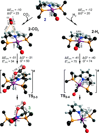 | ||
| Fig. 1 Optimized structures of reaction intermediates and transition states involved in the metal–ligand cooperative activation of H2 and CO2 by 2 (in the graphical representation tBu substituents at the phosphine moieties are simplified for clarity). ZPE-corrected reaction (ΔEZPE) and activation energies (EZPE‡), reaction and activation Gibbs free energies (ΔG° and G‡) are given in kJ mol−1 (for individual elementary steps).47 | ||
The cooperative [1,3]-addition of CO2 (2–CO2 → TS2–3 → 3) is exothermic by −51 kJ mol−1 and proceeds with a low activation barrier of 34 kJ mol−1. When corrected for entropic effects, the reaction and activation Gibbs free energies are, respectively, equal to −31 and 50 kJ mol−1. This evidences a pronounced entropy loss due to the decrease in the degrees of freedom upon the chemical binding of the non-specifically coordinated CO2. The TS2–3 is an early transition state that features a distorted CO2 molecule that forms rather elongated bonds with the basic C1 site of the ligand (r(C1–C2) = 2.543 Å) and the Ru center (r(Ru–O1) = 2.537 Å). The structural properties of TS2–3 suggest that the dominant destabilizing contribution to the activation energy in this case is associated with the bending of the linear CO2 molecule necessary for the attack by the basic C1 centre at the PNP* pincer arm. The promoting effect of the concomitant coordination to Ru is the polarization of the CO2 molecule and stabilization of the negative charge at the O1 atom (Mulliken atomic charge in TS2–3 is −0.280 e−) in the course of the [1,3]-addition reaction towards 3. The optimized structure of 3 agrees well with the single-crystal X-ray diffraction data reported by Milstein and co-workers.49 The accuracy of the current computational method is supported by a good match between the calculated E‡ and G‡ (85 and 81 kJ mol−1, respectively) and the experimental values (94 and 83 kJ mol−1)49 determined for the reverse 3 → 2 + CO2 transformation.
Dissociation of H2 over 2 gives a bis-hydrido Ru-PNP complex 4 (2–H2 → TS2–4 → 4, Fig. 1) and proceeds with an activation barrier (EZPE‡ = 75 kJ mol−1) substantially higher than that computed for the reaction with CO2. Because H2 is effectively immobilized within the σ-complex 2–H2, the entropic contribution to the reaction and activation energy in this case is negligible. As a result the overall reaction 2 + H2 → 4 (ΔG° = −40 kJ mol−1) is more thermodynamically favourable than the reaction with CO2 (2 + CO2 → 3, ΔG° = −8 kJ mol−1). In the TS2–4, the polarized H2 molecule undergoes a heterolytic cleavage over a Ru⋯C1 acid–base pair. The calculated Mulliken charges on the H1 and H2 atoms in TS2–4 are −0.056 and 0.187 e−, respectively. The high activation barrier in this case is most likely due to the relatively large distance between the acid and the base sites in the dearomatized Ru-PNP* (2: r(C1⋯Ru) = 3.191 Å) that hampers the efficient stabilization of both the H− and H+ species formed in the transition state.
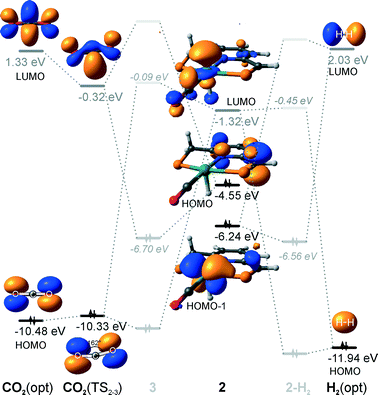
An insight into the origin of the different coordination behaviour and reactivity of 2 towards CO2 and H2 can be obtained from the frontier orbital analysis (Fig. 3). An unoccupied dz2 orbital on Ru and an occupied formally pz orbital on basic C1 contribute mostly to the LUMO and HOMO of 2. HOMO-1 is dominated by an occupied Ru dyz orbital. These molecular orbitals (MOs) cannot form a positive overlap with the π* LUMO and n HOMO orbitals of linear non-perturbed CO2. Their linear combination leads to a non-bonding interaction. This explains the non-specific coordination of carbon dioxide in 2–CO2. The change of hybridization of the C atom in CO2 upon bending (CO2*) make a positive orbital overlap between LUMO of CO2* and HOMO of 2 possible. The relatively small energy gap between these orbitals enhances the acid–base interaction resulting in a very low barrier of the [1,3]-addition of CO2 to 2.
HOMO σ and LUMO σ* orbitals of H2 can be involved in donation and back-donation interactions with LUMO and HOMO − 1 orbitals of 2, respectively, in 2–H2 σ-complex. However, because of the large energy difference between the interacting orbitals, binding within the molecular complex is weak (Fig. 1). The specific coordination of H2 to 2 promotes the formation of 4. In support of the above proposition, the high energy barrier for H2 dissociation is due to the distant location of the base site. Indeed, the complexation with H2 does not change the properties of the HOMO.
These results suggest that the preference towards the formation of complexes 3 and 4 during the catalytic CO2 hydrogenation can be altered by varying the reaction conditions. Indeed, whereas the reaction of 2 with H2 to the bis-hydrido complex 4 is more thermodynamically favourable, the alternative path towards the CO2 adduct 3 proceeds with a much lower activation barrier. This implies that by increasing partial pressure of H2 in the reaction mixture, the formation of 4 can be promoted. However, in the presence of excess base necessary to promote catalytic CO2 hydrogenation, one cannot exclude the transient formation of the dearomatized species 2, which can also contribute to the catalytic activity of the Ru-PNP catalyst. To understand the behaviour of this system, analysis of reaction paths over these three alternative potentially active species is necessary.
CO2 hydrogenation over 4
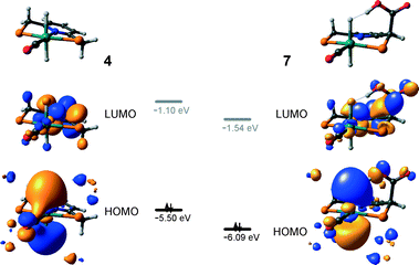
The calculated reaction energy diagram for the catalytic cycle I (Scheme 2) of CO2 hydrogenation by bis-hydrido Ru-PNP complex 447 is shown in Fig. 3. The starting point of the reaction is an energy-neutral binding of CO2 to 4 resulting in 4–CO2. Weak intermolecular contacts between the O atoms of CO2 and acidic CH2 protons of the PNP pincer arms in 4–CO2 (r(O⋯H) = 2.584 Å) direct the CO2 coordination towards the Ru–H moiety. This allows a facile attack of CO2 by Ru-bound hydride (Mulliken charge on the Ru-bound H atom is −0.152 e−) resulting in a formate anion (4–CO2 → TS4–5 → 5*). The reaction is exothermic by −13 kJ mol−1 and shows a very low activation barrier of 23 kJ mol−1. Similar to [1,3]-CO2 addition to 2, the reaction is triggered by the increased acidity of the sp2-like C atom in bent CO2 moiety formed in TS4–5 that ensures an efficient overlap between the s orbital of the H− ligand being one of the main contributors of HOMO (4) (Fig. 4) and LUMO of CO2* (Fig. 2). Note that HOMO in complex 4 lies 1 eV lower than that in 2 indicating a lower nucleophilicity of the H− ligand compared to the basic C1 centre in complexes 4 and 2, respectively. This is in line with the much higher exothermicity of the cooperative CO2 activation by 2.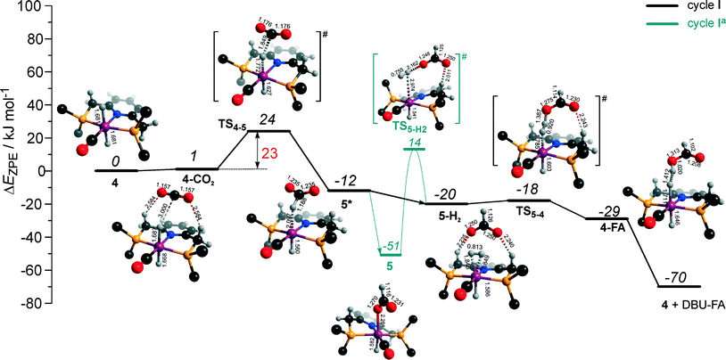 | ||
| Fig. 3 DFT computed reaction energy diagram and optimized structures of the intermediate and transition states (CH3 groups at the tBu substituents of the PNP ligand are omitted for clarity) for the hydrogenation of CO2 over 4.47 | ||
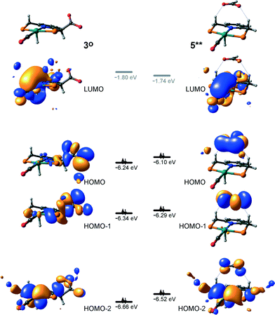
At the next step Ru⋯H-coordinated HCOO− anion is replaced by H2 yielding a cationic σ-H2 Ru-PNP complex charge-compensated by HCOO− hydrogen bonded with the CH2 moieties of the ligand (5* + H2 → 5–H2). Subsequent heterolytic dissociation of H2 over an acid–base pair composed of the Ru centre and the adjacent formate anion results in a molecular complex of formic acid with 4 (4–FA). Despite a lower nucleophilicity of the HCOO− moiety (EHOMO(5**) = −6.10 eV, Fig. 5) compared to the C1 site in 2 (EHOMO(2) = −4.55 eV, Fig. 3), the direct availability of a proton-accepting species in the immediate vicinity of the dissociating H2 molecule leads to a less strained TS5–4 transition state structure and, accordingly, to an extremely low activation barrier for the reaction. Indeed, the reactive moiety Ru⋯H–H in TS5–4 is characterized by substantially shorter interatomic distances (r(Ru⋯H) = 1.785 Å and r(H⋯H) = 0.920 Å, Fig. 3) compared to the respective parameters in TS2–4 (r(Ru⋯H) = 1.881 Å and r(H⋯H) = 0.989 Å, Fig. 3). Reaction of 4–FA with the DBU base at the next step releases DBU–FA product and regenerates the initial complex 4.
Alternatively, 5* can rearrange to a stable complex 5 (ref. 67) (5* → 5, ΔEZPE = −39 kJ mol−1, Fig. 3) featuring a direct Ru–O coordination (r(Ru–O) = 2.261 Å). Previously, this species has been proposed to be a resting state in the catalytic cycle by 4.47 To proceed with the catalytic cycle (path Ia), the ionization of 5 (i.e. the formation of an ion pair 5*) and the replacement of HCOO− with H2 has to take place. This reaction shows an activation barrier of 65 kJ mol−1.
Metal–ligand cooperative CO2 hydrogenation by 2
The dearomatized pyridine-based Ru pincer complexes have been suggested to play key role in catalytic CO2 hydrogenation.46 The catalytic cycle II over 2 largely overlaps with cycle I discussed above. The two cycles differ in the mechanism of product formation via the transformations of the formato-complex 5* (Scheme 2), which in cycle II involves a direct deprotonation of the PNP ligand resulting in a one-step FA formation. The DFT computed reaction energy diagram for CO2 hydrogenation over 2 is shown in Fig. 6. Heterolytic dissociation of H2 over 2 yielding 4 is the first and the most energy demanding step of the cycle (E‡ = 76 kJ mol−1). It is followed by a facile CO2 activation by the bis-hydrido species 4 resulting in 5*. The weakly bound HCOO− in 5* plays then a role of a base that attacks the acidic CH2 moiety at the PNP pincer arm resulting in its deprotonation and the formation of FA molecule hydrogen-bonded with a basic C1 site at Ru-PNP* (2–FA). The reaction and activation energies are very similar for this step (ΔEZPE = 46 kJ mol−1 and E‡ = 47 kJ mol−1). Because of the very high basicity of the deprotonated pincer arm in 2, the reverse FA dissociation reaction is effectively barrierless. Therefore, to promote the catalytic cycle FA has to be eliminated from the complex by a strongly exothermic (ΔEZPE = −51 kJ mol−1) reaction with DBU base. The DBU–FA product is formed at this step and the original catalytic species 2 is regenerated.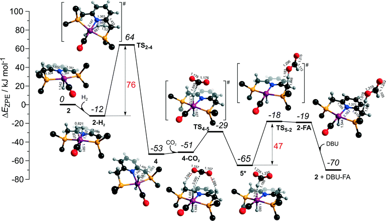 | ||
| Fig. 6 DFT computed reaction energy diagram and optimized structures of the intermediate and transition states (CH3 groups at the tBu substituents of the PNP ligand are omitted for clarity) for the direct hydrogenation of CO2 over 2 (cycle II).47 | ||
CO2 hydrogenation by 3
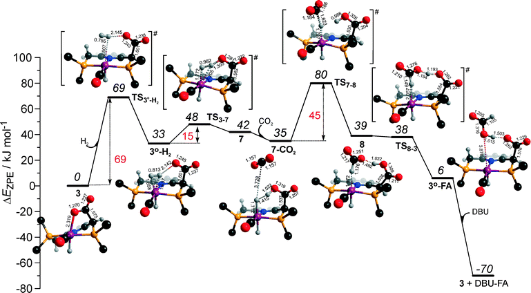
Potentially, the CO2 adduct 3 can also act as catalytic species for CO2 hydrogenation. In a very recent study by Huff and Sanford on the mechanism of CO2 hydrogenation by a related Ru-PNN catalyst, the role of an Ru-PNN CO2 adduct analogous to 3 has been discussed.46 Although the mechanism for the catalytic reaction over such species was proposed, the authors concluded that it most likely represents a minor pathway in the overall catalytic process. The catalytic activity of the CO2 adduct at elevated temperatures predominantly stems from the reversible binding of CO2 that allows its transformations to a more reactive dearomatized Ru-PNN* complex under the catalytic conditions. Similarly, in the presence of H2 or H2–CO2 mixture, 3 transforms directly to 5, from which cycle Ia can in principle be initiated. The catalytic activities of these complexes are very different47 suggesting the principle possibility of the 3-catalyzed hydrogenation of CO2.The DFT-computed reaction energy diagram for the 3-catalyzed hydrogenation of CO2 is shown in Fig. 7. To initiate the cycle III, complex 3 has to be activated via a rather unfavourable reaction (ΔE = 33 kJ mol−1, E‡ = 69 kJ mol−1) with H2 that results in an opening of the Ru–O coordination and the formation of a 3°–H2. The coordinated dihydrogen molecule undergoes then a heterolytic dissociation over a cationic Ru center and the basic carboxylate moiety on the pincer arm in 3°. The reaction in this case is less energetically favorable and proceeds with a higher barrier (3°–H2 → TS3–7 → 7, ΔE = 9 kJ mol−1, E‡ = 15 kJ mol−1) than the respective step in cycle I (5–H2 → TS5–4 → 4–FA, ΔE = −9 kJ mol−1, E‡ = 2 kJ mol−1). This is in line with the differences in energies of the frontier orbitals (Fig. 5) and, accordingly, the acid–base properties, of the reactive moieties in these complexes. Reaction of 7 with CO2 yields a formato-complex 8 that resembles 5* in cycle I. This step is slightly endothermic (ΔE = 4 kJ mol−1) and shows an activation barrier of 45 kJ mol−1. The lower reactivity of 7 towards CO2 compared to that of catalyst 4 stems from the decreased hydricity of the Ru–H moiety interacting with the carboxylic acid group at the pincer arm of 7 (Fig. 4). Subsequent barrierless proton transfer from the ligand-bound –COOH moiety to the HCOO− anion in 8 results in FA hydrogen-bonded to the activated complex 3° (FA–3°). The removal of FA by the reaction with DBU regenerates the initial CO2-adduct 3.
Implications for catalysis
The computational results presented above suggest that all candidate Ru-PNP complexes 2–4 can be formed under the CO2 hydrogenation conditions and may contribute to the overall catalytic reaction. To directly compare the above three alternative mechanism for CO2 hydrogenation by Ru-PNP, we further analysed reaction Gibbs free energy diagrams for these three catalytic cycles (Fig. 8).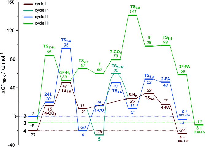 | ||
| Fig. 8 A comparison of Gibbs free energy diagrams for catalytic cycles I, II and III plotted relative to the dearomatized Ru-PNP* species 2. | ||
The bis-hydrido complex 4 provides the lowest free energy reaction path for the conversion of CO2 to FA–DBU along the cycle I (Fig. 8). The reaction in this case does not involve the metal–ligand cooperation in Ru-PNP and proceeds via the direct hydrogenolysis of transient species 5* containing a non-coordinated formate anion (5* + H2 → 5–H2 → 4–FA, Fig. 3 and 8). DFT calculations predict that the reaction along this path shows a very low apparent activation energy68 of 24 kJ mol−1 (4 + CO2 → 5*, Fig. 3) associated with the initial CO2 activation step. The free energy barrier ΔG‡ for this transformation is 67 kJ mol−1 (Fig. 8). The subsequent facile hydrogenolysis of 5* is competing with its rearrangement to a formato-complex 5. 5 is the most thermodynamically stable species among the Ru-PNP intermediates considered here. This finding is in line with the results of experimental 1H NMR reactivity studies evidencing the exclusive formation of 5 under near-catalytic conditions.47 The polarization of 5 followed by H2 insertion (5 + H2 → 5–H2, Fig. 3) is the rate-determining step (RDS) of the catalytic mechanism involving the formation of 5 (cycle Ia). This route is characterized by Eapp‡,DFT of 65 kJ mol−1 that is comparable to the activation energies predicted for the elementary reaction steps involved in the alternative catalytic cycles II and III promoted by, respectively, complexes 2 and 3.
The data in Fig. 6 and 8 suggest that the cooperative H2 activation by 2 represents the RDS of the MLC mechanism along the cycle II. Since the formation of an 2–H2 σ-complex is thermodynamically unfavourable, this route should proceed with a moderate Eapp‡,DFT of 64 kJ mol−1 (2 + H2 → 4, Fig. 6). In free energy terms this pathway shows a rather high free energy barrier of 95 kJ mol−1 (2 + H2 → 4, Fig. 8). The catalysis on the CO2 adduct 3 (cycle III) proceeds via a sequence of thermodynamically unfavourable steps (Fig. 8). Although the initial coordination of H2 (3 + H2 → 3°–H2, Fig. 7) shows an activation energy (E‡) of only 69 kJ mol−1, the overall barrier in this case is represented by the energy difference between the initial state 3 and the high energy TS7–8 for the CO2 activation (Eapp‡,DFT = 80 kJ mol−1Fig. 7, ΔGapp‡,DFT = 149 kJ mol−1Fig. 8). In line with the experimental findings,47 this points to a lower catalytic activity of 3 compared to that of 2 and 4. Under the catalytic conditions, the contribution of 2 is limited due to the low thermodynamic stability of the reaction intermediates and high activation free energy barriers along the respective MLC path II.
Catalytic CO2 hydrogenation experiments with Ru-PNP catalyst precursor 1 and a strong KOtBu support this proposition. We propose that KOtBu can promote the dearomatization of the PNP pincer ligand60 in the stable intermediates formed in the course of the reaction towards Ru-PNP* complex 2 and therefore ensure the high steady-state concentration of this activated complex under the catalytic conditions. Independent of the reaction medium, a very low activity was observed in this case. Turnover numbers after 2 hour reaction (TON(2 h)) were only 728 and 649 in THF and DMF solvents, respectively. On contrary, when a non-nucleophilic DBU base, which cannot promote the ligand dearomatization,47 was used as a promoter, much higher TON(2 h) values of 12![[thin space (1/6-em)]](https://www.rsc.org/images/entities/char_2009.gif) 829 and 38
829 and 38![[thin space (1/6-em)]](https://www.rsc.org/images/entities/char_2009.gif) 642 in THF and DMF solvents, respectively, were obtained (Table S1, ESI†).
642 in THF and DMF solvents, respectively, were obtained (Table S1, ESI†).
The catalytic CO2 hydrogenation by Ru-PNP complexes is dominated by the competing reaction paths I and Ia realized by the bis-hydrido Ru-PNP complex 4. These paths are differentiated by the mechanism of the transformation of the polarized formate complex 5*. The competing rearrangement (5* → 5, path Ia) and hydrogenolysis (5* + H2 + DBU → 4 + FA–DBU, path I) routes show similar reaction free energy changes (Fig. 8) and involve effectively barrierless transformations (Fig. 3). We therefore speculate that the latter mechanism can be promoted in the presence of an excess H2 that would ensure the rapid substitution of the non-coordinated HCOO− and its replacement with H2 towards 5–H2.
To verify this hypothesis, we investigated the kinetics of CO2 hydrogenation by Ru-PNP complex 1 (Fig. 9) in the presence of DBU with varying H2/CO2 molar ratio (ptotal = 40 bar). At a H2/CO2 molar ratio of 3/1, the reaction showed an apparent activation energy (Eapp‡) of 57 kJ mol−1 that is in very good agreement with the computed value (Eapp‡,DFT) of 65 kJ mol−1 for cycle Ia (Fig. 3).
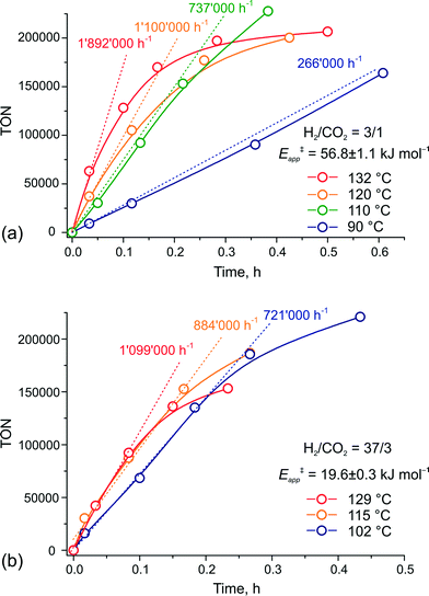 | ||
| Fig. 9 Kinetic traces for CO2 hydrogenation by 1 at different temperatures and H2–CO2 ratio of (a) 3/1 and (b) 37/3 (ptotal = 40 bar). | ||
The rate enhancement previously observed upon a slight increase of the partial pressure of H2 (ref. 22) is in line with the proposition on the rate-determining nature of the 5 + H2 → 5–H2 step in this case. As a result of the high activation energy, a strong temperature dependency of the reaction rate is observed. Whereas the reaction at 132 °C shows an initial turnover frequency (TOF) of 1![[thin space (1/6-em)]](https://www.rsc.org/images/entities/char_2009.gif) 892
892![[thin space (1/6-em)]](https://www.rsc.org/images/entities/char_2009.gif) 000 h−1, the initial TOF at 90 °C is only 266
000 h−1, the initial TOF at 90 °C is only 266![[thin space (1/6-em)]](https://www.rsc.org/images/entities/char_2009.gif) 000 h−1. When the reaction is carried out in the presence of a large excess of H2 (H2/CO2 = 37/3), the apparent activation energy drops to only 20 kJ mol−1, which is in perfect agreement with the value of 24 mol−1 predicted for the direct hydrogenolysis path I (Fig. 3). At a temperature of 129 °C, the reaction shows a TOF of 1
000 h−1. When the reaction is carried out in the presence of a large excess of H2 (H2/CO2 = 37/3), the apparent activation energy drops to only 20 kJ mol−1, which is in perfect agreement with the value of 24 mol−1 predicted for the direct hydrogenolysis path I (Fig. 3). At a temperature of 129 °C, the reaction shows a TOF of 1![[thin space (1/6-em)]](https://www.rsc.org/images/entities/char_2009.gif) 099
099![[thin space (1/6-em)]](https://www.rsc.org/images/entities/char_2009.gif) 000 h−1. In line with the proposal on the RDS nature of the CO2 activation step in cycle I, the lower reaction rate for a high temperature reaction in this case is most likely due to the decreased partial pressure of CO2. An important consequence of the low activation barrier for CO2 hydrogenation at a high H2/CO2 molar ratio is the possibility to achieve high rates of the catalytic reaction at lower temperatures (Fig. 9(b)). An initial rate of 721
000 h−1. In line with the proposal on the RDS nature of the CO2 activation step in cycle I, the lower reaction rate for a high temperature reaction in this case is most likely due to the decreased partial pressure of CO2. An important consequence of the low activation barrier for CO2 hydrogenation at a high H2/CO2 molar ratio is the possibility to achieve high rates of the catalytic reaction at lower temperatures (Fig. 9(b)). An initial rate of 721![[thin space (1/6-em)]](https://www.rsc.org/images/entities/char_2009.gif) 000 h−1 was obtained at 102 °C. From the Arrhenius plot one can estimate TOF values above 100
000 h−1 was obtained at 102 °C. From the Arrhenius plot one can estimate TOF values above 100![[thin space (1/6-em)]](https://www.rsc.org/images/entities/char_2009.gif) 000 h−1 to be reachable at ambient temperature. These findings render the Ru-PNP complex 1 in combination with non-nucleophilic DBU base one of the most active CO2 hydrogenation catalytic system reported to date.
000 h−1 to be reachable at ambient temperature. These findings render the Ru-PNP complex 1 in combination with non-nucleophilic DBU base one of the most active CO2 hydrogenation catalytic system reported to date.
Conclusions
The mechanism of CO2 hydrogenation to DBU formate salt in the presence of homogeneous pyridine-based Ru-PNP pincer catalysts was investigated by means of density functional theory calculations. The focus was on unravelling the complexity of the underlying reaction mechanisms and determining the routes for the optimization of the performance of this catalytic system. Dedicated catalytic tests and kinetic study were carried out to verify the theoretical predictions.Three major interconnected reaction paths catalysed by dearomatised Ru-PNP* complex 2 or by its cooperative adducts with CO2 and H2, Ru-PNP complexes 3 and 4, respectively, were considered. On the basis of the theoretical results it is proposed that depending on the reaction conditions, the relative concentration of these reactive species and their contribution to the overall catalytic performance varies. Whereas formation of 4 upon the reaction of 2 with H2 is thermodynamically preferred, the competing [1,3]-CO2 addition towards 3 is favoured kinetically. We propose that the latter route will dominate in excess strong base needed to ensure a high steady-state concentration of the activated precursor 2 and a high partial pressure of CO2. At increased H2 partial pressure, the reaction will be driven towards the most stable dihydrido-Ru-PNP complex.
The hydrogenation of CO2 catalysed by 3 proceeds via a sequence of highly endothermic elementary steps showing also rather high activation barriers. As a result, the highest apparent activation barrier of 80 kJ mol−1 is predicted for the respective catalytic cycle III. This cycle is also characterized by a prohibitively high overall Gibbs free energy barrier of 149 kJ mol−1. In the case of the catalysis by the dearomatised species 2, metal–ligand cooperation plays an important role in the reaction mechanism. The initial heterolytic H2 dissociation over an acid–base pair formed by the 5-coordinated Ru centre and the deprotonated CH basic site at the PNP* pincer arm is the rate-determining step (Eapp‡,DFT = 64 kJ mol−1, ΔGapp‡,DFT = 95 kJ mol−1). Despite the high intrinsic reactivity of the acid and base sites in Ru-PNP*, their distant location within the rigid dearomatised pincer complex strongly hamper the heterolytic H2 dissociation. When a much less basic HCOO− anion acts as the basic site in related steps over 3° (cycle III) and 5* (cycle I) complexes, much lower activation barriers are predicted. Most of the reaction intermediates involved in the catalytic cycles II and III are rather unstable thermodynamically and their transformations proceed with rather high free energy barriers. This suggests only minor contribution of these reaction paths under common CO2 hydrogenation conditions.
DFT calculations predict that the bis-hydrido Ru-PNP complex 4 is the most active one. CO2 hydrogenation by 4 can follow two mechanisms (cycle I and Ia) that do not involve metal–ligand cooperative steps. A facile CO2 activation by Ru–H moiety resulting in a non-coordinated HCOO− and a 5-coordinated cationic Ru-PNP (5*) represents the initial step in both catalytic cycle. The cycles are distinguished by the mechanism of the subsequent transformations of 5* that, in turn, depends on the partial pressure of H2. Under excess H2, the substitution of the non-coordinated HCOO− anion in 5* with H2 resulting in a σ-complex 5–H2 initiates an almost barrierless sequence of elementary steps towards the completion of the catalytic cycle and the formation of the FA–DBU product. The competing route Ia involves the rearrangement of 5* towards a stable formato-complex 5 that has previously been proposed to be the resting state of the catalytic reaction. The polarization of 5 followed by H2 insertion to yield 5* determines the overall reaction rate for the Ia mechanism and shows an activation barrier of 65 kJ mol−1. The initial CO2 activation is the rate-determining step in cycle I, for which an apparent activation energy of only 24 kJ mol−1 is predicted.
The analysis of experimental reaction kinetics for CO2 hydrogenation by Ru-PNP confirms these theoretical predictions. By increasing the molar H2–CO2 ratio in the catalytic experiment from 3/1 to 37/3, the apparent activation energy decreases from 57 to 20 kJ mol−1, respectively, in a perfect agreement with the computed values. A relatively small temperature dependency of the reaction rate in the latter case points to the possibility of achieving very high catalytic performance in CO2 hydrogenation by Ru-PNP under near-ambient temperatures.
Acknowledgements
E.A.P. gratefully acknowledges the Technology Foundation STW and the Netherlands Organization for Scientific Research (NWO) for his personal VENI grant. SurfSARA and NWO are acknowledged for providing access to supercomputer resources (grant SH-231). The authors thank Dr. L. Leffort (DSM) for the possibility to carry out high-throughput experiments.Notes and references
- M. Cokoja, C. Bruckmeier, B. Rieger, W. A. Herrmann and F. E. Kühn, Angew. Chem., Int. Ed., 2011, 50, 8510–8537 CrossRef CAS PubMed.
- K. Huang, C.-L. Sun and Z.-J. Shi, Chem. Soc. Rev., 2011, 40, 2435–2452 RSC.
- T. Sakakura, J.-C. Choi and H. Yasuda, Chem. Rev., 2007, 107, 2365–2387 CrossRef CAS PubMed.
- C. Maeda, Y. Miyazaki and T. Ema, Catal. Sci. Technol., 2014, 4, 1482–1497 CAS.
- C. J. Whiteoak, N. Kielland, V. Laserna, E. C. Escudero-Adán, E. Martin and A. W. Kleij, J. Am. Chem. Soc., 2013, 135, 1228–1231 CrossRef CAS PubMed.
- M. L. Lejkowski, R. Lindner, T. Kageyama, G. É. Bódizs, P. N. Plessow, I. B. Müller, A. Schäfer, F. Rominger, P. Hofmann, C. Futter, S. A. Schunk and M. Limbach, Chem. – Eur. J., 2012, 18, 14017–14025 CrossRef CAS PubMed.
- L. Zhang, J. Cheng, B. Carry and Z. Hou, J. Am. Chem. Soc., 2012, 134, 14314–14317 CrossRef CAS PubMed.
- B. Chatelet, L. Joucla, J.-P. Dutasta, A. Martinez, K. C. Szeto and V. Dufaud, J. Am. Chem. Soc., 2013, 135, 5348–5351 CrossRef CAS PubMed.
- T. Sakai, Y. Tsutsumi and T. Ema, Green Chem., 2008, 10, 337–341 RSC.
- L. Wu, Q. Liu, I. Fleischer, R. Jackstell and M. Beller, Nat. Commun., 2014, 5, 3091 Search PubMed.
- C. Federsel, R. Jackstell and M. Beller, Angew. Chem., Int. Ed., 2010, 49, 6254–6257 CrossRef CAS PubMed.
- J. F. Hull, Y. Himeda, W.-H. Wang, B. Hashiguchi, R. Periana, D. J. Szalda, J. T. Muckerman and E. Fujita, Nat. Chem., 2012, 4, 383–388 CrossRef CAS PubMed.
- C. A. Huff and M. S. Sanford, J. Am. Chem. Soc., 2011, 133, 18122–18125 CrossRef CAS PubMed.
- S. Wesselbaum, T. vom Stein, J. Klankermayer and W. Leitner, Angew. Chem., Int. Ed., 2012, 51, 7499–7502 CrossRef CAS PubMed.
- Y.-N. Li, R. Ma, L.-N. He and Z.-F. Diao, Catal. Sci. Technol., 2014, 4, 1498–1512 CAS.
- M. Nielsen, E. Alberico, W. Baumann, H.-J. Drexler, H. Junge, S. Gladiali and M. Beller, Nature, 2013, 495, 85–89 CrossRef CAS PubMed.
- R. E. Rodríguez-Lugo, M. Trincado, M. Vogt, F. Tewes, G. Santiso-Quinones and H. Grützmacher, Nat. Chem., 2013, 5, 342–347 CrossRef PubMed.
- F. Joó, ChemSusChem, 2008, 1, 805–808 CrossRef PubMed.
- S. Enthaler, ChemSusChem, 2008, 1, 801–804 CrossRef CAS PubMed.
- A. Boddien, F. Gaertner, C. Federsel, P. Sponholz, D. Mellmann, R. Jackstell, H. Junge and M. Beller, Angew. Chem., Int. Ed., 2011, 50, 6411–6414 CrossRef CAS PubMed.
- C. Fellay, P. J. Dyson and G. Laurenczy, Angew. Chem., Int. Ed., 2008, 47, 3966–3968 CrossRef CAS PubMed.
- G. A. Filonenko, R. van Putten, E. N. Schulpen, E. J. M. Hensen and E. A. Pidko, ChemCatChem, 2014, 6, 1526–1530 CrossRef CAS.
- A. Boddien, C. Federsel, P. Sponholz, D. Mellmann, R. Jackstell, H. Junge, G. Laurenczy and M. Beller, Energy Environ. Sci., 2012, 5, 8907–8911 CAS.
- S.-F. Hsu, S. Rommel, P. Eversfield, K. Muller, E. Klemm, W. R. Thiel and B. Plietker, Angew. Chem., Int. Ed., 2014 DOI:10.1002/anie.201310972.
- M. Drees, M. Cokoja and F. E. Kühn, ChemCatChem, 2012, 4, 1703–1712 CrossRef CAS.
- T. Fan, X. Chen and Z. Lin, Chem. Commun., 2012, 48, 10808–10828 RSC.
- C. Creutz, M. H. Chou, H. Hou and J. T. Muckerman, Inorg. Chem., 2010, 49, 9809–9822 CrossRef CAS PubMed.
- K.-W. Huang, J. H. Han, C. B. Musgrave and E. Fujita, Organometallics, 2006, 26, 508–513 CrossRef.
- T. Schaub and R. A. Paciello, Angew. Chem., Int. Ed., 2011, 50, 7278–7282 CrossRef CAS PubMed.
- C. Federsel, R. Jackstell and M. Beller, Angew. Chem., Int. Ed., 2010, 49, 6254–6257 CrossRef CAS PubMed.
- W. Wang, S. Wang, X. Ma and J. Gong, Chem. Soc. Rev., 2011, 40, 3703–3727 RSC.
- R. Langer, Y. Diskin-Posner, G. Leitus, L. J. W. Shimon, Y. Ben-David and D. Milstein, Angew. Chem., Int. Ed., 2011, 50, 9948–9952 CrossRef CAS PubMed.
- C. Ziebart, C. Federsel, P. Anbarasan, R. Jackstell, W. Baumann, A. Spannenberg and M. Beller, J. Am. Chem. Soc., 2012, 134, 20701–20704 CrossRef CAS PubMed.
- M. S. Jeletic, M. T. Mock, A. M. Appel and J. C. Linehan, J. Am. Chem. Soc., 2013, 135, 11533–11536 CrossRef CAS PubMed.
- P. Munshi, A. D. Main, J. C. Linehan, C.-C. Tai and P. G. Jessop, J. Am. Chem. Soc., 2002, 124, 7963–7971 CrossRef CAS PubMed.
- Y.-Y. Ohnishi, T. Matsunaga, Y. Nakao, H. Sato and S. Sakaki, J. Am. Chem. Soc., 2005, 127, 4021–4032 CrossRef CAS PubMed.
- Y.-Y. Ohnishi, Y. Nakao, H. Sato and S. Sakaki, Organometallics, 2006, 25, 3352–3363 CrossRef CAS.
- A. Urakawa, F. Jutz, G. Laurenczy and A. Baiker, Chem. – Eur. J., 2007, 13, 3886–3899 CrossRef CAS PubMed.
- R. Tanaka, M. Yamashita and K. Nozaki, J. Am. Chem. Soc., 2009, 131, 14168–14169 CrossRef CAS PubMed.
- C. Gunanathan and D. Milstein, Acc. Chem. Res., 2011, 44, 588–602 CrossRef CAS PubMed.
- J. I. van der Vlugt and J. N. H. Reek, Angew. Chem., Int. Ed., 2009, 48, 8832–8846 CrossRef CAS PubMed.
- E. Balaraman and D. Milstein, Top. Organomet. Chem., 2014, 77, 1–25 Search PubMed.
- R. Tanaka, M. Yamashita, L. W. Chung, K. Morokuma and K. Nozaki, Organometallics, 2011, 30, 6742–6750 CrossRef CAS.
- X. Yang, ACS Catal., 2011, 1, 849–854 CrossRef CAS.
- M. S. G. Ahlquist, J. Mol. Catal. A: Chem., 2010, 324, 3–8 CrossRef CAS.
- C. A. Huff and M. S. Sanford, ACS Catal., 2013, 3, 2412–2416 CrossRef CAS.
- G. A. Filonenko, M. P. Conley, C. Copéret, M. Lutz, E. J. M. Hensen and E. A. Pidko, ACS Catal., 2013, 3, 2522–2526 CrossRef CAS.
- C. A. Huff, J. W. Kampf and M. S. Sanford, Organometallics, 2012, 31, 4643–4645 CrossRef CAS.
- M. Vogt, M. Gargir, M. A. Iron, Y. Diskin-Posner, Y. Ben-David and D. Milstein, Chem. – Eur. J., 2012, 18, 9194–9197 CrossRef CAS PubMed.
- J. Zhang, G. Leitus, Y. Ben-David and D. Milstein, Angew. Chem., Int. Ed., 2006, 45, 1113–1115 CrossRef CAS PubMed.
- C. Adamo and V. Barone, J. Chem. Phys., 1999, 110, 6158–6170 CrossRef CAS.
- Gaussian 09 Revision D.01, M. J. Frisch, G. W. Trucks, H. B. Schlegel, G. E. Scuseria, M. A. Robb, J. R. Cheeseman, G. Scalmani, V. Barone, B. Mennucci, G. A. Petersson, H. Nakatsuji, M. Caricato, X. Li, H. P. Hratchian, A. F. Izmaylov, J. Bloino, G. Zheng, J. L. Sonnenberg, M. Hada, M. Ehara, K. Toyota, R. Fukuda, J. Hasegawa, M. Ishida, T. Nakajima, Y. Honda, O. Kitao, H. Nakai, T. Vreven, J. A. Montgomery Jr., J. E. Peralta, F. Ogliaro, M. Bearpark, J. J. Heyd, E. Brothers, K. N. Kudin, V. N. Staroverov, R. Kobayashi, J. Normand, K. Raghavachari, A. Rendell, J. C. Burant, S. S. Iyengar, J. Tomasi, M. Cossi, N. Rega, N. J. Millam, M. Klene, J. E. Knox, J. B. Cross, V. Bakken, C. Adamo, J. Jaramillo, R. Gomperts, R. E. Stratmann, O. Yazyev, A. J. Austin, R. Cammi, C. Pomelli, J. W. Ochterski, R. L. Martin, K. Morokuma, V. G. Zakrzewski, G. A. Voth, P. Salvador, J. J. Dannenberg, S. Dapprich, A. D. Daniels, Ö. Farkas, J. B. Foresman, J. V. Ortiz, J. Cioslowski and D. J. Fox, Gaussian, Inc., Wallingford CT, 2009 Search PubMed.
- Y. Zhao and D. G. Truhlar, J. Chem. Theory Comput., 2009, 5, 324–333 CrossRef CAS.
- R. Valero, R. Costa, I. de P. R. Moreira, D. G. Truhlar and F. Illas, J. Chem. Phys., 2008, 128, 114003 CrossRef PubMed.
- R. Krishnan, J. S. Binkley, R. Seeger and J. A. Pople, J. Chem. Phys., 1980, 72, 650–654 CrossRef CAS.
- A. D. McLean and G. S. Chandler, J. Chem. Phys., 1980, 72, 5639–5648 CrossRef CAS.
- P. J. Hay and W. R. Wadt, J. Chem. Phys., 1985, 82, 270–283 CrossRef CAS.
- P. J. Hay and W. R. Wadt, J. Chem. Phys., 1985, 82, 299–310 CrossRef CAS.
- D. Andrae, U. Häußermann, M. Dolg, H. Stoll and H. Preuß, Theor. Chim. Acta, 1990, 77, 123–141 CrossRef CAS.
- B. Gnanaprakasam, J. Zhang and D. Milstein, Angew. Chem., Int. Ed., 2010, 49, 1468–1471 CrossRef CAS PubMed.
- E. Khaskin, M. A. Iron, L. J. W. Shimon, J. Zhang and D. Milstein, J. Am. Chem. Soc., 2010, 132, 8542–8543 CrossRef CAS PubMed.
- J. Kubas Gregory, Acc. Chem. Res., 1988, 21, 120–128 CrossRef.
- V. B. Kazansky and E. A. Pidko, Catal. Today, 2005, 110, 281–293 CrossRef CAS.
- R. H. Crabtree and M. Lavin, J. Chem. Soc., Chem. Commun., 1985, 1661–1662 RSC.
- R. H. Crabtree, Acc. Chem. Res., 1990, 23, 95–101 CrossRef CAS.
- G. Alcaraz, M. Grellier and S. Sabo-Etienne, Acc. Chem. Res., 2009, 42, 1640–1649 CrossRef CAS PubMed.
- M. Ahlquist, G. Fabrizi, S. Cacchi and P.-O. Norrby, J. Am. Chem. Soc., 2006, 128, 12785–12793 CrossRef CAS PubMed.
- E app ‡,DFT is defined as the difference in ZPE-corrected energy of the species corresponding to the highest and the lowest energy point in the reaction Gibbs free energy diagram for a particular proposed catalytic cycle (Fig. 8).
Footnote |
| † Electronic supplementary information (ESI) available: Reaction free energy diagrams for catalysis by 4 in DMF, results of small-scale CO2 hydrogenation experiments with 1. See DOI: 10.1039/c4cy00568f |
| This journal is © The Royal Society of Chemistry 2014 |

