 Open Access Article
Creative Commons Attribution 3.0 Unported Licence
Coke formation in the oxidative dehydrogenation of ethylbenzene to styrene by TEOM
C.
Nederlof
a,
P.
Vijfhuizen
a,
V.
Zarubina
b,
I.
Melián-Cabrera
b,
F.
Kapteijn
a and
M.
Makkee
*a
aDelft University of Technology, Faculty of Applied Sciences, Chemical Engineering Department, Section of Catalysis Engineering, Julianalaan 136, NL 2628 BL Delft, The Netherlands. E-mail: m.makkee@tudelft.nl; Fax: +31 15 278 5006; Tel: +31 15 278 1391
bUniversity of Groningen, Institute of Technology & Management, Chemical Reaction Engineering, Nijenborgh 4, NL 9747 AG Groningen, The Netherlands
First published on 25th June 2014
Abstract
A packed bed microbalance reactor setup (TEOM-GC) is used to investigate the formation of coke as a function of time-on-stream on γ-Al2O3 and 3P/SiO2 catalyst samples under different conditions for the ODH reaction of ethylbenzene to styrene. All samples show a linear correlation of the styrene selectivity and yield with the initial coverage of coke. The COX production increases with the coverage of coke. On the 3 wt% P/SiO2 sample, the initial coke build-up is slow and the coke deposition rate increases with time. On alumina-based catalyst samples, a fast initial coke build-up takes place, decreasing with time-on-stream, but the amount of coke does not stabilize. A higher O2![[thin space (1/6-em)]](https://www.rsc.org/images/entities/char_2009.gif) :
:![[thin space (1/6-em)]](https://www.rsc.org/images/entities/char_2009.gif) EB feed ratio results in more coke, and a higher temperature results in less coke. This coking behaviour of Al2O3 can be described by existing “monolayer–multilayer” models. Further, the coverage of coke on the catalyst varies with the position in the bed. For maximal styrene selectivity, the optimal coverage of coke should be sufficient to convert all O2, but as low as possible to prevent selectivity loss by COX production. This is in favour of high temperature and low O2
EB feed ratio results in more coke, and a higher temperature results in less coke. This coking behaviour of Al2O3 can be described by existing “monolayer–multilayer” models. Further, the coverage of coke on the catalyst varies with the position in the bed. For maximal styrene selectivity, the optimal coverage of coke should be sufficient to convert all O2, but as low as possible to prevent selectivity loss by COX production. This is in favour of high temperature and low O2![[thin space (1/6-em)]](https://www.rsc.org/images/entities/char_2009.gif) :
:![[thin space (1/6-em)]](https://www.rsc.org/images/entities/char_2009.gif) EB feed ratios. The optimal coke coverage depends in a complex way on all the parameters: temperature, the O2
EB feed ratios. The optimal coke coverage depends in a complex way on all the parameters: temperature, the O2![[thin space (1/6-em)]](https://www.rsc.org/images/entities/char_2009.gif) :
:![[thin space (1/6-em)]](https://www.rsc.org/images/entities/char_2009.gif) EB feed ratio, reactant concentrations, and the type of starting material.
EB feed ratio, reactant concentrations, and the type of starting material.
Introduction
Studies on catalyst coking are usually carried out to gain insight into catalyst deactivation. In catalytic cracking, the carbon deposits block the acid sites that are active for the cracking reactions, causing catalyst deactivation.1,2 The oxidative dehydrogenation (ODH) reaction of hydrocarbons is an exception to this. The selective conversion of ethyl benzene (EB) to styrene (ST) is not catalysed by the catalyst that is loaded into the reactor but by the coke that is formed during the reaction.3–8 Similarly, in the methanol to olefins (MTO) and related processes, firstly a ‘hydrocarbon pool’ has to be formed that generates the desired products in concert with the Brønsted acid sites in the catalyst, but it also leads to deactivation.9 By studying the coke formation,10 information on the real catalyst in these processes can be obtained. In ODH, coke can be formed in several ways: oligomerisation of olefins, poly-alkylation of aromatics, and condensation of aromatics.2For ODH of EB, it is generally accepted that the oxygen groups on the surface of the deposited coke,11,12 especially the quinone groups,13 are the catalytically selective active sites. These can undergo a redox reaction where ethylbenzene (EB) is the reducing agent and oxygen is the oxidizing agent.14 It is also postulated that (oxygen) radicals take part in the dehydrogenation mechanism.15 In the past, a few ODH studies focused on the formation of carbon deposits on aluminas16,17 and the rate of formation on metal pyrophosphates.5 Several factors influence the formation of coke on Al2O3 in ODH, namely:16
• A higher oxygen partial pressure will give more coke.
• A maximum is present when varying temperature.
• The acidity of the catalyst increases the coke formation.
According to Lisovskii et al., these factors result in a stable amount of coke on an Al2O3 catalyst, a monolayer that covers the catalyst surface.16 For alumina, the amount of coke monolayer normalised for the specific surface area is about 0.54 mg m−2.16 For the metal pyrophosphate catalysts, a monolayer corresponds to about 0.8 mg m−2.5
Among the tools that are available for the study of coke formation dynamics are microbalance reactors. A special type of microbalance reactor is the tapered element oscillating microbalance (TEOM) that uses the natural frequency of the oscillating tapered element to determine mass changes.18 The TEOM reactor has a well-defined gas phase (fixed-bed reactor) and a high mass resolution and stability and can operate under conditions that are suitable for practical operations.19 It does not suffer from external mass-transfer limitations or gas bypassing, as is the case for hanging basket-type microbalance reactors.18 The TEOM has found applications in many topics such as coke deposition, adsorption and diffusion in zeolites, gas storage, and synthesis of carbon fibres.18–22
In our own work and in the literature, many catalyst samples for the ODH of EB have been tested and discussed.2–8,14–16,23–26 The optimal performances of four of our tested samples are summarized in Table 1. γ-Al2O3 is the reference sample used in this work, reaching 29% ST yield at 82% ST selectivity. The addition of a phosphorus promoter8,27–29 improves the ODH performance of the Al2O3 to some extent, 2% points increase in ST yield and 1% point increase in ST selectivity. The high-temperature (1000 °C) calcined Al2O3 sample Al-1000 shows a larger improvement in the performance with 36% ST yield and 86% ST selectivity. The 3 wt% P/SiO2 sample is one of the best-performing samples that were tested, with 51% ST yield at 91% ST selectivity.
| Sample | Temp. [°C] | O2![[thin space (1/6-em)]](https://www.rsc.org/images/entities/char_2009.gif) : :![[thin space (1/6-em)]](https://www.rsc.org/images/entities/char_2009.gif) EB EB |
ST yield | ST selectivity | COX selectivity |
|---|---|---|---|---|---|
| γ-Al2O3 | 450 | 0.6 | 29% | 82% | 16% |
| 1.3P/Al2O3 | 475 | 0.6 | 31% | 83% | 15% |
| Al-1000 | 450 | 0.6 | 36% | 86% | 13% |
| 3P/SiO2 | 475 | 0.6 | 51% | 91% | 8% |
The objective of this work is to obtain detailed real-time information on the formation of the carbon deposits on γ-Al2O3, Al2O3 calcined at 1000 °C, 1.3 wt% P/Al2O3 and 3 wt% P/SiO2 catalyst samples. Real-time information on the coke amount as a function of time-on-stream is one of the missing pieces in understanding the ODH process, as this is usually done by post-mortem analysis of the sample by TGA.17 This is done using a TEOM-GC reactor setup, which provides continuous data on the catalyst sample mass and the catalyst performance in the ODH reaction with time-on-stream (TOS).
Experimental
Catalyst preparation
The γ-Al2O3 extrudates (Ketjen CK300, 0.57 ml g−1, 190 m2 g−1, now Albemarle) are crushed, sieved to 212–425 μm particles and used as such, or calcined at 1000 °C for 8 h (Al-1000), or modified with a phosphorus promoter (H3PO4). The SiO2 support (silica NorPro, SS61138, 1.00 ml g−1, 250 m2 g−1; 213 m2 g−1 according to our internal BET measurements) is crushed, sieved to 212–425 μm and dried at 150 °C in vacuum for 4 hours. The phosphorus is introduced by impregnation using the incipient wetness method with a 5% excess of the pore volume. The required amounts of H3PO4 are mixed with Mili-Q® demineralised water, after which the support is impregnated with the solution. The wetted support is shaken vigorously with an automatic shaker to homogenize the impregnated support. Next, it is dried at 70 °C in static air overnight followed by calcination in a static air calcination oven at 500 °C for 8 hours. The heating rate is set at 4 °C min−1. The P loading is set as wt% elemental phosphorus (3 wt% is denoted as 3P/SiO2), but presumably the phosphorus is present in its oxidic form of P2O5 after calcination and under ODH reaction conditions. Similarly, sample 1.3P/Al2O3 contains 1.3 wt% elemental phosphorus. An overview of the catalyst samples and their properties is given in Table 2.The TEOM reactor setup
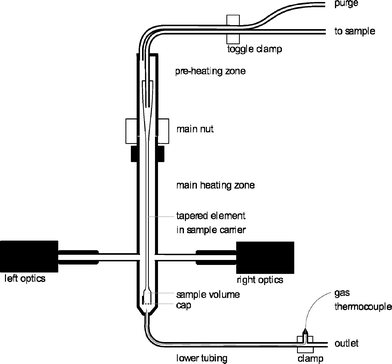
The tapered element oscillating microbalance (TEOM) reactor setup is an excellent tool for measuring the mass changes of a sample under reaction conditions. This mass change can be the result of coke formation, adsorption, desorption, oxidation, or reduction.10,18–22 A mass change of less than 1 microgram can be measured. This means that a change in the gas composition can be already detected by this method. A commercial (now discontinued) Rupprecht and Patashnick (R&P) 1500 Pulse Mass Analyser is used. A schematic layout of the reactor part is shown in Fig. 1.The working principle of the balance is based on the natural oscillation frequency of the reactor that is at the end of a tapered element. The frequency of this oscillation depends on the weight of the sample. This frequency is accurately measured using an infrared beam perpendicular to the oscillation. A change in the frequency from f0 to f1 and from time t0 to t1 results in a total mass change (of gas and solids in the sample volume) that is calculated according to eqn (1). The spring constant K0 is determined by using a calibration weight on the reactor.
 | (1) |
In the reactor setup, a catalyst sample with a maximum weight of 100 mg can be used. This is held in position by a quartz wool plug at the top and at the bottom, and a metal cap with small holes in it is used to close the reactor end. There are two temperature zones, a preheating zone that can be heated from 50 °C to 500 °C and a reaction zone that can be heated from 50 °C to 600 °C. The operating pressure is between 0 barg (ambient pressure) and 30 barg. A reaction gas mixture can be formed from three gases and one liquid feed that is evaporated. The flows are all accurately controlled by six mass flow controllers. The used gases are helium, air and carbon dioxide. All flows are reported under the normal conditions of 20 °C and 1 atm. The ethylbenzene is fed as a liquid (LMFC, max 0.6 g h−1).
At the start of an experiment, the reactor (450–500 °C) and preheating zone (200 °C) are heated up under a helium flow (25 ml min−1) through the reactor and a helium purge flow (100 ml min−1) along the reactor. When the sample mass is stabilised (normalised standard deviation <3 × 10⁻⁶), the reaction is started by switching to the reactor feed that consists of air (0.12–1.07 ml min−1), helium (25 ml min−1), and ethylbenzene vapour (0.13 g h−1 or 0.45 ml min−1 vapour). This gives an EB concentration of 1.7 vol%. The helium bypass purge flow is not changed. The O2![[thin space (1/6-em)]](https://www.rsc.org/images/entities/char_2009.gif) :
:![[thin space (1/6-em)]](https://www.rsc.org/images/entities/char_2009.gif) EB molar feed ratio is varied between 0.05 and 0.5. The (diluent + O2)
EB molar feed ratio is varied between 0.05 and 0.5. The (diluent + O2)![[thin space (1/6-em)]](https://www.rsc.org/images/entities/char_2009.gif) :
:![[thin space (1/6-em)]](https://www.rsc.org/images/entities/char_2009.gif) EB molar feed ratio is 58. The W/FEB is between 37 and 64 gcat h mol−1. The GHSVTOT is 20.000 l l−1 h−1.
EB molar feed ratio is 58. The W/FEB is between 37 and 64 gcat h mol−1. The GHSVTOT is 20.000 l l−1 h−1.
The sample is regenerated in between experiments under the reaction conditions by stopping the EB feed, yielding a diluted air mixture (0.1–0.9 vol% O2). The experiments are highly reproducible after each regeneration.
An online GC, type Chrompack CP9001, with two channels was used for analysis of the product gas stream. One channel uses an FID for the analysis of hydrocarbons with a 60-cm 12% UCW column. The other channel uses a TCD for the analysis of permanent gases (O2, N2, CO, CO2) with a Poraplot Q and a molsieve column. The molsieve column uses a bypass for CO2 and H2O analysis. The EB conversion XEB, selectivities of ST, coke and COX (Seli) and ST yield YST are based on ethylbenzene concentrations and calculated based on eqn (2)–(6). Mcoke is 120 g mol−1, assuming a molecular composition for coke of C8H8O.29 Although the mass increase by coke is measured, the overall carbon balance does not close 100% since the CO and CO2 concentrations were near the GC detection limit.
 | (2) |
 | (3) |
 | (4) |
 | (5) |
| YST = XEB × SelST | (6) |
In addition to the calibration procedure of the TEOM setup itself, the setup was also verified by separate determination of the amount of coke using a microbalance (MettlerToledo TGA/SDTA851e).
The 6-flow reactor setup
The data in Table 1 and Fig. 13 in this work are based on ODH experiments performed in a parallel fixed-bed reactor setup that was described in detail in our previous publications.23–26 To obtain the catalyst samples for Fig. 13, the total catalyst amount is split into 8 beds with glass beads in between, allowing for individual post-mortem coke amount determination of each of the 8 beds.Catalyst characterization
The final amount of coke deposited is determined off-line by TGA (MettlerToledo TGA/SDTA851e, 20 mg sample of spent catalyst, 100 ml min−1 air and 50 ml min−1 He flow mixture) using a ramp of 3 °C min−1 from RT to 723 °C. Surface area, pore volume and pore size distribution are determined by N2 adsorption at −196 °C (Quantachrome Autosorb 6B). The samples are pretreated overnight in nitrogen at 250 °C.Results
The ODH performance in the TEOM reactor
With the TEOM-GC setup, both the catalyst performance and the catalyst weight are monitored with time-on-stream (TOS). A typical example of the catalyst performance of Al2O3 in the TEOM reactor is shown in Fig. 2 (left). At the 0.15 O2![[thin space (1/6-em)]](https://www.rsc.org/images/entities/char_2009.gif) :
:![[thin space (1/6-em)]](https://www.rsc.org/images/entities/char_2009.gif) EB feed ratio, a styrene yield of 23% at a 96% ST selectivity is reached after 20 h TOS and does not change up to a TOS of 70 h. This performance is better than that expected from comparable 6-flow experiments at the 0.2 O2
EB feed ratio, a styrene yield of 23% at a 96% ST selectivity is reached after 20 h TOS and does not change up to a TOS of 70 h. This performance is better than that expected from comparable 6-flow experiments at the 0.2 O2![[thin space (1/6-em)]](https://www.rsc.org/images/entities/char_2009.gif) :
:![[thin space (1/6-em)]](https://www.rsc.org/images/entities/char_2009.gif) EB feed ratio (14% ST yield at 88% ST selectivity).23–26 The TOS required to reach this optimum performance is longer in the TEOM setup. Initially the coke selectivity is high; 15%, this quickly decreases to below 1% after 10 h TOS. The initial ST yield and ST selectivity are 8% and 77%, respectively. With increasing TOS, the ST selectivity and yield increase, but the coke selectivity and COX selectivity decrease. The catalyst performance stabilizes after about 10–20 h, depending on the reaction conditions. The O2 conversion is around 95% during the whole experiment.
EB feed ratio (14% ST yield at 88% ST selectivity).23–26 The TOS required to reach this optimum performance is longer in the TEOM setup. Initially the coke selectivity is high; 15%, this quickly decreases to below 1% after 10 h TOS. The initial ST yield and ST selectivity are 8% and 77%, respectively. With increasing TOS, the ST selectivity and yield increase, but the coke selectivity and COX selectivity decrease. The catalyst performance stabilizes after about 10–20 h, depending on the reaction conditions. The O2 conversion is around 95% during the whole experiment.
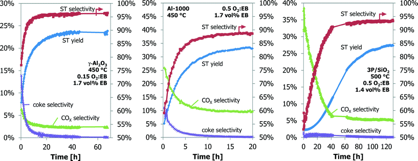 | ||
| Fig. 2 The ODH performance as a function of time-on-stream for the γ-Al2O3, Al-1000 and 3P/SiO2 samples in the TEOM reactor. | ||
The performance in the ODH reaction of the Al-1000 and 3P/SiO2 samples are shown in Fig. 2 (middle and right). With increasing TOS, both ST yield and ST selectivity increase. For Al-1000, they increase from 5% to 34% and from 60% to 89%, respectively. For 3P/SiO2, the increase is from 4% to 16% and from 57% to 87%, respectively. The oxygen conversion of Al-1000 increases from 50% to 90% after 20 h TOS. For 3P/SiO2, the oxygen conversion is constant at about 50%. Again, the ODH performance of the Al-1000 is better than that expected from the 6-flow experiments. The ODH performance of the 3P/SiO2 is, however, worse than expected.23–26
Catalyst coverage with coke
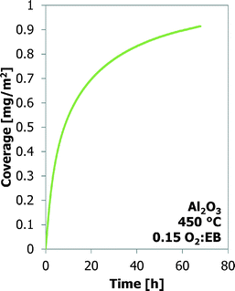
Many experiments are performed with bare γ-Al2O3 at three temperatures and four O2![[thin space (1/6-em)]](https://www.rsc.org/images/entities/char_2009.gif) :
:![[thin space (1/6-em)]](https://www.rsc.org/images/entities/char_2009.gif) EB feed ratios. These results are shown in Fig. 3. It is assumed that all the mass increases are only the result of carbon deposition. At the same O2
EB feed ratios. These results are shown in Fig. 3. It is assumed that all the mass increases are only the result of carbon deposition. At the same O2![[thin space (1/6-em)]](https://www.rsc.org/images/entities/char_2009.gif) :
:![[thin space (1/6-em)]](https://www.rsc.org/images/entities/char_2009.gif) EB feed ratio the final coke coverage at about 20 h TOS decreases from 0.71 m2 g−1 to 0.38 m2 g−1 with increasing temperature from 450 °C to 500 °C. Initially the coke formation rates are the same, but at a higher temperature the amount of coke levels off earlier. With increasing O2
EB feed ratio the final coke coverage at about 20 h TOS decreases from 0.71 m2 g−1 to 0.38 m2 g−1 with increasing temperature from 450 °C to 500 °C. Initially the coke formation rates are the same, but at a higher temperature the amount of coke levels off earlier. With increasing O2![[thin space (1/6-em)]](https://www.rsc.org/images/entities/char_2009.gif) :
:![[thin space (1/6-em)]](https://www.rsc.org/images/entities/char_2009.gif) EB feed ratio from 0.05 to 0.20 at a constant temperature, the final coverage of coke increases from 0.41 mg m−2 to 0.72 mg m−2. The initial coke formation rates increase with an increasing O2
EB feed ratio from 0.05 to 0.20 at a constant temperature, the final coverage of coke increases from 0.41 mg m−2 to 0.72 mg m−2. The initial coke formation rates increase with an increasing O2![[thin space (1/6-em)]](https://www.rsc.org/images/entities/char_2009.gif) :
:![[thin space (1/6-em)]](https://www.rsc.org/images/entities/char_2009.gif) EB feed ratio. With time-on-stream, the coke deposition becomes slower. Fig. 4 shows that the coke coverage keeps increasing with the time-on-stream, although the coke deposition rate decreases with the time-on-stream, but does not become zero.
EB feed ratio. With time-on-stream, the coke deposition becomes slower. Fig. 4 shows that the coke coverage keeps increasing with the time-on-stream, although the coke deposition rate decreases with the time-on-stream, but does not become zero.
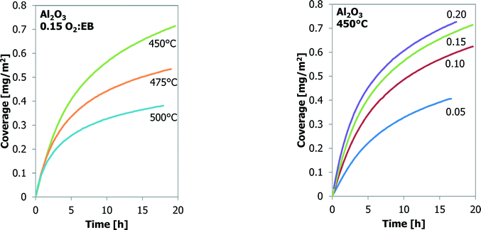 | ||
Fig. 3 The effect of temperature (left) and O2![[thin space (1/6-em)]](https://www.rsc.org/images/entities/char_2009.gif) : :![[thin space (1/6-em)]](https://www.rsc.org/images/entities/char_2009.gif) EB feed ratio (right) on coke coverage (TEOM) for Al2O3 as a function of time-on-stream. EB feed ratio (right) on coke coverage (TEOM) for Al2O3 as a function of time-on-stream. | ||
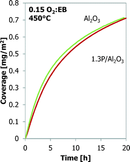
A comparison between bare alumina and phosphorus-loaded alumina is shown in Fig. 5. The latter shows better performance in the ODH reaction. The coke coverage evolution is nearly identical to that of the Al2O3 sample, even though the Al2O3 support and their surface areas are different (Table 2).
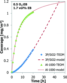
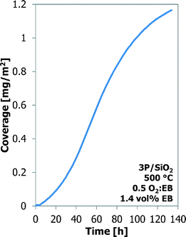
Also, a thermal treatment results in better ODH performance of the Al-1000 than that of the γ-Al2O3.24,25 A phosphorus-loaded silica support, such as 3P/SiO2, shows the best results in the ODH reaction.25,26 Their coke coverage evolution is shown in Fig. 6. The 1000 °C calcined alumina shows a behaviour similar to that of the bare alumina, but the coverage by coke is higher, 1.02 mg m−2 for Al-1000 against 0.70 mg m−2 for γ-Al2O3, after 20 h TOS. The P/SiO2 sample shows a completely different coke deposition behaviour. Initially the coke build-up is very slow, but it increases continuously in time. Also a higher temperature is required to observe sufficient coke formation and ODH on the P/SiO2 sample. After 20 h TOS only 0.38 mg m−2 of coke is deposited.
The experiment with the 3P/SiO2 sample was repeated under slightly different conditions (30 vs. 25 ml min−1 helium carrier flow, 50 vs. 46.1 mg of sample) to observe the coke build-up during a longer time-on-stream (130 h TOS). The results are presented in Fig. 7. Initially the coke build-up is very slow, but increases with TOS. After 60 h TOS or above 0.6 mg m−2 coverage the coke build-up on 3P/SiO2 becomes slower and resembles more the behaviour of the Al2O3 samples.
Modelling coke coverage
The coke build-up on alumina with time-on-stream has been modelled with the “monolayer–multilayer” model5,31,32 (eqn (7)) that describes the formation of coke with two mechanisms: monolayer coke formation on the surface of the catalyst and multilayer coke formation on top of the existing coke. The monolayer amount is related to the physical limitations of the catalyst surface, represented in the model by the constant kCm,max. Both monolayer and multilayer growth are functions of the monolayer coke amount Cm. All constants are considered to be a function of temperature and oxygen concentration (eqn (8)). | (7) |
 | (8) |
Individual fitting of each experiment and plotting of the fit parameters to temperature and O2 concentration showed that k1 and kCm,max are functions of the temperature and k1 and k2 are functions of the O2 concentration. Finally, all experiments were fitted together as a group; the resulting fit parameters are given in Table 3.
| Parameter | k n,0 | E a,n [kJ] | n O2,n | n n |
|---|---|---|---|---|
| k 1 [gcoke gcat−1 h−1] | 8.17 × 10⁷ | 99.2 | 1 | 2 |
| k 2 [h−1] | 9.92 × 10⁻² | 2 | 1 | |
| k C m,max [gcoke gcat−1 h−1] | 6.62 × 10⁻⁶ | −61.6 |
The data from the experiments with Al-1000 and 3P/SiO2 are also modelled with the “monolayer–multilayer” model5,31,32 (Fig. 6). For 3P/SiO2 to fit the model, a low kCm,max and a high k2 were found compared to the alumina samples. The S-curve behaviour of the longer TOS experiment with 3P/SiO2 in Fig. 7 could not be captured by the “monolayer–multilayer” model in eqn (7).
Styrene yield as a function of coke coverage
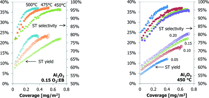
When the catalyst performance and mass data are coupled, a linear relationship is observed for the styrene yield as a function of the coke coverage (Fig. 8). The slope of the curve increases at a higher temperature. For higher O2![[thin space (1/6-em)]](https://www.rsc.org/images/entities/char_2009.gif) :
:![[thin space (1/6-em)]](https://www.rsc.org/images/entities/char_2009.gif) EB feed ratios the slope does not change, but the off-set value of the ST yield at 0 mg of coke increases. At the higher styrene yields and coke coverage, the data from the experiments start to deviate from a linear relationship. At the O2
EB feed ratios the slope does not change, but the off-set value of the ST yield at 0 mg of coke increases. At the higher styrene yields and coke coverage, the data from the experiments start to deviate from a linear relationship. At the O2![[thin space (1/6-em)]](https://www.rsc.org/images/entities/char_2009.gif) :
:![[thin space (1/6-em)]](https://www.rsc.org/images/entities/char_2009.gif) EB feed ratio of 0.15 and at 500 °C the deviation starts at a coverage of about 0.25 mg m−2, at 475 °C it is 0.40 mg m−2 and at 450 °C no deviation is observed (Fig. 8).
EB feed ratio of 0.15 and at 500 °C the deviation starts at a coverage of about 0.25 mg m−2, at 475 °C it is 0.40 mg m−2 and at 450 °C no deviation is observed (Fig. 8).
The styrene yield as a function of the coke coverage for a 70 h TOS experiment over the γ-Al2O3 is shown in Fig. 9. Under these conditions the styrene yield increases linearly with coke coverage up to 0.70 mg m−2 (20 h TOS). The yield increases slightly, but above 0.80 mg m−2 (35 h TOS) the styrene yield does not change anymore with an increase in the coke coverage.
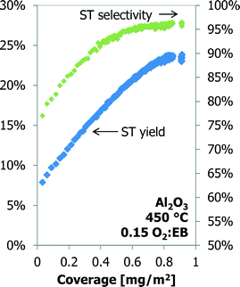 | ||
| Fig. 9 The styrene yield and selectivity as a function of coke coverage for Al2O3 up to 70 h time-on-stream. | ||
The styrene yield as a function of the coke coverage for Al-1000 and 3P/SiO2 is shown in Fig. 11. Although the temperature and sample amounts are different, both samples show an almost identical dependency of the styrene yield on the coke coverage. A linear fit gives a productivity of 7 g styrene (g coke)−1 h−1. Above a 30% styrene yield and a coverage of about 0.80 mg m−2, the calcined alumina sample shows a deviation from the linear relationship between ST yield and coke coverage.
Also for the 3P/SiO2 sample under slightly different conditions (30 vs. 25 ml min−1 helium carrier flow, 50 vs. 46.1 mg of sample) the styrene yield increases linearly with the coke coverage up to about 20% ST yield and 0.6 mg m−2 coverage, above which it starts deviating from the initial linear relationship (Fig. 10). The gap in the GC data is due to a temporary GC failure. The styrene yield curves in Fig. 10 and 11 are exactly parallel. Additionally, above a coke coverage of about 0.2 mg m−2 the amount of carbon dioxide produced also shows a linear relationship with the coke coverage. At this coverage the amount of CO2 produced is the minimum.
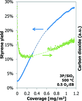 | ||
| Fig. 10 Styrene yield (closed symbols) and selectivity (open symbols) as a function of coke coverage for Al-1000 and for 3P/SiO2. | ||
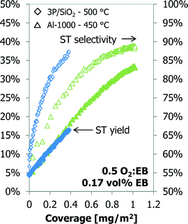 | ||
| Fig. 11 Styrene yield (left) and carbon dioxide (right) as a function of the coke coverage for 3P/SiO2. | ||
TGA analysis
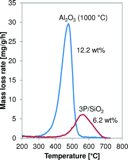
The spent Al2O3 (1000 °C) and 3P/SiO2 samples are analysed by temperature-programmed thermogravimetric analysis (TGA) in air at 3 °C min−1, and their oxidation profiles are shown in Fig. 12. The maximum oxidation temperature of the coke on 3P/SiO2 is higher than that of alumina-based coke, 565 °C versus 480 °C, respectively. This indicates a higher reactivity of the coke on the Al2O3.Distribution of coke in a catalyst bed
An experiment was done in the 6-flow reactor setup with γ-Al2O3, where the catalyst bed was split into 8 separate parts. This gives an idea of the build-up of coke over the catalyst bed length. This catalyst was tested in the 6-flow setup using our standard screening protocol.23–26 The coverage of coke as a function of the bed length is shown in Fig. 13. The maximum coverage of coke, 2 mg m−2, is located in the second section of the catalyst bed. The top section of the catalyst bed has a lower coke coverage (1.2 mg m−2). Towards the end of the bed, the coverage of coke decreases to 0.75 mg m−2. The reactor is operated in down-flow operation.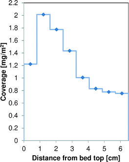 | ||
| Fig. 13 Distribution of the coke coverage on γ-Al2O3 as a function of the catalyst bed length, after the standard 62 h testing protocol in the 6-flow reactor. | ||
The characterisation by TGA also indicates small variations in the temperature of maximum soot oxidation: the top catalyst section at 466 °C, the next at 476 °C, the next two at 472 °C and the bottom four at 470 °C.
Discussion
The oxidative dehydrogenation reaction could be an attractive reaction to replace the industrially used endothermic direct dehydrogenation reaction that is equilibrium limited. The ODH reaction is catalysed by the coke that is formed and not by the initial ‘catalyst’.3–5,7,8,11–16,23–30 Therefore, it is very important to get more insight into this coke and its performance. So far, some general correlations have been found5,16,17 that are investigated in more detail in this paper with the TEOM-GC setup.ODH performance in the TEOM reactor
Before going into detail on the formation of coke and the catalytic activity of this coke, a few other observations need to be discussed, like the different performance of the TEOM reactor compared to the 6-flow reactor. In the TEOM reactor, activation is slower (10–20 h vs. 5 h) and the ODH performance is better (YST, 23% vs. 14%; SelST, 95% vs. 88%; O2![[thin space (1/6-em)]](https://www.rsc.org/images/entities/char_2009.gif) :
:![[thin space (1/6-em)]](https://www.rsc.org/images/entities/char_2009.gif) EB, 0.15 vs. 0.2). From our previous work it is known that the ODH performance over a bare alumina at different temperatures (450–500 °C) changes no more than 1%.23–26 Also, the lower O2
EB, 0.15 vs. 0.2). From our previous work it is known that the ODH performance over a bare alumina at different temperatures (450–500 °C) changes no more than 1%.23–26 Also, the lower O2![[thin space (1/6-em)]](https://www.rsc.org/images/entities/char_2009.gif) :
:![[thin space (1/6-em)]](https://www.rsc.org/images/entities/char_2009.gif) EB feed ratio contradicts with the higher ST yield.23–26 Such differences were not expected, as both setups are fixed-bed reactors that operate under similar conditions like space velocity, O2
EB feed ratio contradicts with the higher ST yield.23–26 Such differences were not expected, as both setups are fixed-bed reactors that operate under similar conditions like space velocity, O2![[thin space (1/6-em)]](https://www.rsc.org/images/entities/char_2009.gif) :
:![[thin space (1/6-em)]](https://www.rsc.org/images/entities/char_2009.gif) EB feed ratio and temperature. The obvious explanation for these differences between the two setups is found in the reactant concentrations. These are lower in the TEOM reactor, and the inlet EB concentration is 1.7 vol% against 9 vol% in the 6-flow reactor. At lower concentrations, the processes that occur (coke deposition, coke gasification and ODH) may become slower, but at the same O2
EB feed ratio and temperature. The obvious explanation for these differences between the two setups is found in the reactant concentrations. These are lower in the TEOM reactor, and the inlet EB concentration is 1.7 vol% against 9 vol% in the 6-flow reactor. At lower concentrations, the processes that occur (coke deposition, coke gasification and ODH) may become slower, but at the same O2![[thin space (1/6-em)]](https://www.rsc.org/images/entities/char_2009.gif) :
:![[thin space (1/6-em)]](https://www.rsc.org/images/entities/char_2009.gif) EB feed ratio the ST yield and selectivity hardly change.16 This is also seen in the coke build-up experiments on 3P/SiO2 in Fig. 6 and 7 that are done with the same feed of reactants, but with a slightly higher dilution (25 vs. 30 ml min−1 helium) and thus different concentrations in the gas mixture. This has a large effect on the coke build-up. After 20 h time-on-stream the amount of coke in the first experiment is 0.38 mg m−2; the second experiment needs 50 h TOS to reach this coke coverage. The reactant concentrations appear to have a large effect on the coke build-up at these very low concentrations.
EB feed ratio the ST yield and selectivity hardly change.16 This is also seen in the coke build-up experiments on 3P/SiO2 in Fig. 6 and 7 that are done with the same feed of reactants, but with a slightly higher dilution (25 vs. 30 ml min−1 helium) and thus different concentrations in the gas mixture. This has a large effect on the coke build-up. After 20 h time-on-stream the amount of coke in the first experiment is 0.38 mg m−2; the second experiment needs 50 h TOS to reach this coke coverage. The reactant concentrations appear to have a large effect on the coke build-up at these very low concentrations.
Another possible explanation for the ODH performance differences is the quality of the analysis. With the 6-flow this is more advanced because of the higher concentrations and a more accurate calibration. But even with these low concentrations, an error estimation results in only a ± 0.5% point ST selectivity difference and a ± 0.1% point difference in ST yield. An error in the O2![[thin space (1/6-em)]](https://www.rsc.org/images/entities/char_2009.gif) :
:![[thin space (1/6-em)]](https://www.rsc.org/images/entities/char_2009.gif) EB feed ratio will result in a little larger deviation, but still smaller than the differences in the ODH performance that are observed between both setups.
EB feed ratio will result in a little larger deviation, but still smaller than the differences in the ODH performance that are observed between both setups.
Axial dispersion phenomena are thought to be mainly responsible for the improved performance. The Péclet number of the TEOM reactor is about 9× smaller than that of the 6-flow reactor, implying a more CSTR-like behaviour with more averaged concentrations of reactants over the catalyst bed than the integral concentration profiles of a plug flow reactor. This can lead to improved performance over an Al2O3 catalyst.26
The worse than expected performance in the ODH reaction for the 3P/SiO2 sample is attributed to the side effects of the setup, especially when operated at >500 °C over this catalyst.25 When oxygen is still available after the reaction, as is the case with the 3P/SiO2 sample, it will react further, resulting in a worse performance than expected. Whenever possible in the experiments, full conversion of O2 over the reactor was aimed for, but with the 3P/SiO2 sample this could not be achieved.
Despite the differences between the TEOM and 6-flow setup, it can be stated that the general observed trends are similar. Although the time scales and conditions are different, their performance with regard to temperature, molar O2![[thin space (1/6-em)]](https://www.rsc.org/images/entities/char_2009.gif) :
:![[thin space (1/6-em)]](https://www.rsc.org/images/entities/char_2009.gif) EB feed ratio and catalyst samples are in agreement for both setups.
EB feed ratio and catalyst samples are in agreement for both setups.
Modelling coke formation
The temperature and oxygen dependencies of the coke deposition with TOS (Fig. 3) are very well captured in the “monolayer–multilayer” model. The maximum “monolayer” amount of coke on a catalyst (kCm,max) is a function of temperature and is less related to the available surface area (physically constant) than thought before. The “monolayer” growth rate is a function of temperature and O2![[thin space (1/6-em)]](https://www.rsc.org/images/entities/char_2009.gif) :
:![[thin space (1/6-em)]](https://www.rsc.org/images/entities/char_2009.gif) EB (1st order). The “multilayer” growth rate constant itself is not a function of temperature; however, because of its dependency on the “monolayer”, the temperature dependency is already included, and in addition it has a 2nd order O2
EB (1st order). The “multilayer” growth rate constant itself is not a function of temperature; however, because of its dependency on the “monolayer”, the temperature dependency is already included, and in addition it has a 2nd order O2![[thin space (1/6-em)]](https://www.rsc.org/images/entities/char_2009.gif) :
:![[thin space (1/6-em)]](https://www.rsc.org/images/entities/char_2009.gif) EB dependency for its growth rate. When using this model to optimize the reaction conditions for slow deactivation and thus minimum coke growth, high temperature and low O2
EB dependency for its growth rate. When using this model to optimize the reaction conditions for slow deactivation and thus minimum coke growth, high temperature and low O2![[thin space (1/6-em)]](https://www.rsc.org/images/entities/char_2009.gif) :
:![[thin space (1/6-em)]](https://www.rsc.org/images/entities/char_2009.gif) EB are favourable. This is in line with conclusions from our staged O2 feeding work.25
EB are favourable. This is in line with conclusions from our staged O2 feeding work.25
A possible extension of the “monolayer–multilayer” model would be to include a saturation of the catalyst with coke, as towards the high coke loadings there will be an effect of pore filling and rapidly reducing available surface area. Data in Fig. 13 show coverages of up to 2 mg m−2, much higher than was obtained in the TEOM. According to the model, under those conditions it would take about 30 h to reach such coverages, where in reality the experiment lasted for 62 h.
The initial coke formation on 3P/SiO2 can also be described by the “monolayer–multilayer” model, but with a low kCm,max and a high k2 it does not fit the description of “monolayer–multilayer” coke formation. Surface-coke (slow) vs. coke-on-coke (fast) formation would be a better description, where coke-on-coke is likely also taking place in the planar direction on the (inactive) surface. For higher coverages on 3P/SiO2 the “monolayer–multilayer” model cannot describe the coke formation. A different or extended model is required.
Coke coverage and ODH performance
The ODH performance is very dependent on the O2![[thin space (1/6-em)]](https://www.rsc.org/images/entities/char_2009.gif) :
:![[thin space (1/6-em)]](https://www.rsc.org/images/entities/char_2009.gif) EB feed ratio. However, the ST yield, as a function of the coke coverage (Fig. 8 (right)), initially has the same linear slope for all O2
EB feed ratio. However, the ST yield, as a function of the coke coverage (Fig. 8 (right)), initially has the same linear slope for all O2![[thin space (1/6-em)]](https://www.rsc.org/images/entities/char_2009.gif) :
:![[thin space (1/6-em)]](https://www.rsc.org/images/entities/char_2009.gif) EB feed ratios, showing that the initial activity of the coke is similar under different O2
EB feed ratios, showing that the initial activity of the coke is similar under different O2![[thin space (1/6-em)]](https://www.rsc.org/images/entities/char_2009.gif) :
:![[thin space (1/6-em)]](https://www.rsc.org/images/entities/char_2009.gif) EB feed ratio conditions. The reaction temperature does not have a large effect on the ODH performance, but it does have a large effect on the coke coverage as a function of time-on-stream (Fig. 8 (left)). At all 3 reaction temperatures, 95% SelST at 20% YST is reached, but at lower coke coverage at higher temperature. This clearly shows the temperature dependency of a catalyst like coke is in the ODH reaction.
EB feed ratio conditions. The reaction temperature does not have a large effect on the ODH performance, but it does have a large effect on the coke coverage as a function of time-on-stream (Fig. 8 (left)). At all 3 reaction temperatures, 95% SelST at 20% YST is reached, but at lower coke coverage at higher temperature. This clearly shows the temperature dependency of a catalyst like coke is in the ODH reaction.
At increasing coke coverages, the linear correlation between the styrene yield and the coverage of coke does not hold anymore (cf.Fig. 8). At the point that it starts to deviate from the initial linear correlation, sufficient coke is available to catalyse the ‘selective’ ODH reaction. The coke formation continues, whilst the ODH performance does not change. Overall, the coke catalyst becomes less efficient. Eventually the excess of coke will have an effect on the ODH performance, as more COX is produced and the styrene yield is decreasing (Fig. 10).25
Activity of coke
In the literature, it is claimed that adding a mineral acid, like phosphoric acid, changes the composition and reactivity of the coke.16,27–29 Based on the data presented in this work, the largest factor that determines the performance is the coverage of coke. Its composition and reactivity can still explain some diverging results. The phosphorus-loaded alumina shows nearly the same coke coverage as the γ-Al2O3 (Fig. 5), but has a slightly better ODH performance in the 6-flow.The coke deposits on the 3P/SiO2 and Al-1000 samples have the same productivity, but at a different temperature (Fig. 11), and the TGA data (Fig. 12) also suggest different reactivity of the coke on the samples. A comparison of all available ST yields as a function of the coke coverage is shown in Fig. 14, corrected for the yield at zero coverage. Comparing the styrene yields to the ST yield of normal γ-Al2O3 at similar coke coverage and reaction temperature, the coke on Al-1000 is more active and the coke on 3P/SiO2 is less active than that on normal γ-Al2O3. This is supported by the activity of the coke in TGA, where the coke on 3P/SiO2 needs a higher oxidation temperature.23,24 The TGA profiles in Fig. 12 cannot be compared directly to the profiles presented by Nederlof et al. (2013)23 because the heating rate was 3 °C min−1 compared to 10 °C min−1 in the other papers. This causes a shift in the oxidation temperatures. However, the trend of the activity of the coke for ODH and oxidation temperature in TGA is similar.
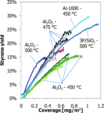 | ||
| Fig. 14 ST yields, corrected for the ST yield at zero coke coverage, as a function of coverage of coke for all experiments. | ||
Deactivation
All experiments with alumina-based catalysts show the same behaviour of quick initial coke deposition and a decreasing coking rate with time-on-stream (Fig. 3–7). For a stable catalyst operation, this is preferred, as it means that the coverage of coke on the sample will not change fast with longer time-on-stream. The ODH performance of alumina is quite stable with time, or in other words, the coke formation and gasification rates are nearly in balance. A very small net coke formation still occurs, but it takes a very long time (>50 h TOS at 10 vol% EB) before the extra coke has a negative effect on the ODH performance.25,26 Modelling gives the insight that monolayer coke coverage is quickly approached and mostly multilayer coke deposition occurs. In terms of the catalyst stability, the opposite is presented by the 3P/SiO2 sample that displays a slow initial coke build-up but increasing coking rates with time-on-stream (Fig. 7). The ODH performance of 3P/SiO2 in the 6-flow setup shows an optimum after a 3 h TOS, with a minimum COX formation, and then deactivates.25,26 This deactivation is caused by excessive coking that shifts the oxygen balance to COX production instead of styrene. The 130 h run with 3P/SiO2 also shows this increase in the COX production (Fig. 10) after a minimum in the CO2 production at a low coke coverage of 0.2 mg m−2. Any further increase in the coke coverage gives an increased CO2 production. At the optimum ODH performance in the 6-flow setup (3 h TOS), the coke formation, coke gasification and ODH reactions are not in balance. The TEOM experiment with the 3P/SiO2 catalyst shows that the coking rate will eventually decrease with time (Fig. 7), but by the time that the coke formation rate decreases, the performance of the P/SiO2 will be far from its optimum in comparison with the normal flow experiments.25Perspective to other studies
In the work of Lisovskii et al.16 it appeared that a monolayer coverage of the coke is obtained when the pseudo steady-state is reached (optimal ST yield and selectivity), which was determined at 0.54 mg m−2 over several Al2O3 samples (at O2![[thin space (1/6-em)]](https://www.rsc.org/images/entities/char_2009.gif) :
:![[thin space (1/6-em)]](https://www.rsc.org/images/entities/char_2009.gif) EB = 1, 0.17 vol% EB and 425 °C). This TEOM study shows that the coke coverage mainly depends on the O2
EB = 1, 0.17 vol% EB and 425 °C). This TEOM study shows that the coke coverage mainly depends on the O2![[thin space (1/6-em)]](https://www.rsc.org/images/entities/char_2009.gif) :
:![[thin space (1/6-em)]](https://www.rsc.org/images/entities/char_2009.gif) EB feed ratio and the reaction temperature (also at the pseudo steady-state). The theoretical coverage of a monolayer of graphene of 0.76 mg m−2 is even surpassed by the Al-1000 and 3P/SiO2 samples before reaching their optimal ST yield at a high O2
EB feed ratio and the reaction temperature (also at the pseudo steady-state). The theoretical coverage of a monolayer of graphene of 0.76 mg m−2 is even surpassed by the Al-1000 and 3P/SiO2 samples before reaching their optimal ST yield at a high O2![[thin space (1/6-em)]](https://www.rsc.org/images/entities/char_2009.gif) :
:![[thin space (1/6-em)]](https://www.rsc.org/images/entities/char_2009.gif) EB feed ratio of 0.5. Therefore, we hypothesize that coke formation occurs more like stacks of islands (3-dimensional) instead of monolayers (2-dimensional) in the case of graphene-like structures on the support surface, where every layer has a similar ODH activity. The surface density of such coke islands can be higher for supports with a high acid site density such as γ-Al2O3 and lower for supports with a low acid site density such as 3P/SiO2.28,30 Coke is able to form at the acid sites and also at the edges and on top of existing coke (‘multilayer’), but at a slower rate. This is supported by the presented modelling results with the “monolayer–multilayer” models.5,31,32
EB feed ratio of 0.5. Therefore, we hypothesize that coke formation occurs more like stacks of islands (3-dimensional) instead of monolayers (2-dimensional) in the case of graphene-like structures on the support surface, where every layer has a similar ODH activity. The surface density of such coke islands can be higher for supports with a high acid site density such as γ-Al2O3 and lower for supports with a low acid site density such as 3P/SiO2.28,30 Coke is able to form at the acid sites and also at the edges and on top of existing coke (‘multilayer’), but at a slower rate. This is supported by the presented modelling results with the “monolayer–multilayer” models.5,31,32
The presented data are not in full agreement with the claim by Lisovskii et al.16 that the amount of coke is stable. There is a continuous net build-up of coke on the catalyst (Fig. 4), but this is very small and only clearly observed on a longer time scale of tens of hours. On an hour-to-hour basis the amount of coke is nearly constant, especially when less sensitive equipment than a TEOM is used to determine the amount of coke.
Distribution of coke along the catalyst bed
The build-up of coke along the catalyst bed in the 6-flow setup is intriguing (Fig. 13). At the first section of the catalyst bed where the oxygen concentration is the highest, less coke is present than in the next section of the catalyst bed. The reactivity of the coke is also highest in this top section, as indicated by the temperature of maximum coke oxidation. Perhaps most of the COX is already formed in the top part of the catalyst bed, reducing the local coverage of coke, but also lowering the oxygen concentration, which is beneficial for the ST selectivity.25 Remember that COX formation requires 6.5–10.5 moles of O2 per mole of EB, and ST production requires only 0.5. Most of the styrene will be formed just below the top part of the bed that already contains sufficient coke to have full oxygen conversion. However, for coke to form, it also needs O2 to be available. The contributions of these 3 reactions (COX, ST, and coke formation) result in an O2 profile over the reactor like the one shown in Fig. 15 and a coke profile over the reactor like the one in Fig. 13, that look very similar when excluding the first part of the bed. More coke will be formed where more oxygen is available. It is also possible that the top sections of the bed are already partly deactivated due to the high coke coverage. The slightly higher temperatures of maximum coke oxidation in the top sections of the bed could indicate this. It is emphasized that these experiments are done in an integral mode and not in a differential mode.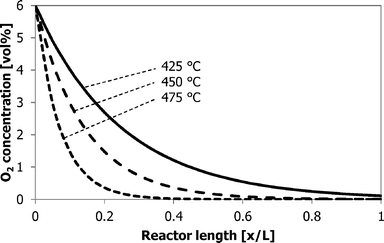 | ||
| Fig. 15 Schematic O2 concentration profile as a function of the reactor bed length at the different reaction temperatures. | ||
Conclusions
This investigation into the formation of coke and the rate thereof on several catalysts and under different conditions again shows the complexity of the ODH process. Coke is the catalyst for the reaction. Modification of the support material can change the activity and selectivity of the coke, but deactivation is inherent to the ODH reaction, as after initial fast coke formation all samples continuously show a very small, but positive coke build-up with time-on-stream as a result of nearly balancing coke formation and gasification rates. The coke build-up on alumina can be modelled with existing “monolayer–multilayer” models. This shows that the “monolayer” coke amount depends on temperature, where “monolayer” and “multilayer” coke formation are a function of both temperature and O2![[thin space (1/6-em)]](https://www.rsc.org/images/entities/char_2009.gif) :
:![[thin space (1/6-em)]](https://www.rsc.org/images/entities/char_2009.gif) EB feed ratio, 1st and 2nd order, respectively. This work supports the existing correlations:
EB feed ratio, 1st and 2nd order, respectively. This work supports the existing correlations:
• The styrene yield shows a linear correlation with the initial coke build-up.
• A higher oxygen partial pressure gives more coke.
• Under operation at full oxygen conversion, a higher temperature will result in less coke without a change in the ODH performance.
• A higher coke loading results in more COX.
The amount of coke depends on the temperature, O2![[thin space (1/6-em)]](https://www.rsc.org/images/entities/char_2009.gif) :
:![[thin space (1/6-em)]](https://www.rsc.org/images/entities/char_2009.gif) EB feed ratio, reactant concentrations, time-on-stream, and the type of starting material. Furthermore, in the integral reactor operation the coverage of coke varies with the position in the bed. For an optimal performance in ODH, a sufficient but low coverage of coke needs to be available, converting all oxygen at minimal CO2 formation. This will lead to high temperature and low O2
EB feed ratio, reactant concentrations, time-on-stream, and the type of starting material. Furthermore, in the integral reactor operation the coverage of coke varies with the position in the bed. For an optimal performance in ODH, a sufficient but low coverage of coke needs to be available, converting all oxygen at minimal CO2 formation. This will lead to high temperature and low O2![[thin space (1/6-em)]](https://www.rsc.org/images/entities/char_2009.gif) :
:![[thin space (1/6-em)]](https://www.rsc.org/images/entities/char_2009.gif) EB feed ratios (staged feeding).25 The exact optimal coverage depends on all of the abovementioned parameters.
EB feed ratios (staged feeding).25 The exact optimal coverage depends on all of the abovementioned parameters.
Acknowledgements
This research is supported by the Dutch Technology Foundation STW, which is the applied science division of NWO, and the Technology Program of the Ministry of Economic Affairs, Agriculture and Innovation (Green and Smart Process Technologies, GSPT). CB&I is acknowledged for financial support.References
- D. L. Trimm, Appl. Catal., 1983, 5, 263–290 CrossRef CAS.
- J. R. RostrupNielsen, Catal. Today, 1997, 37, 225–232 CrossRef CAS.
- M. F. R. Pereira, J. J. M. Orfao and J. L. Figueiredo, Appl. Catal., A, 1999, 184, 153–160 CrossRef CAS.
- F. Cavani and F. Trifiro, Appl. Catal., A, 1995, 133, 219–239 CrossRef CAS.
- G. E. Vrieland, J. Catal., 1988, 111, 14–22 CrossRef CAS.
- G. R. Meima and P. G. Menon, Appl. Catal., A, 2001, 212, 239–245 CrossRef CAS.
- M. F. R. Pereira, J. J. M. Orfao and J. L. Figueiredo, Appl. Catal., A, 2001, 218, 307–318 CrossRef CAS.
- E. Echigoya, H. Sano and M. Tanaka, Proc. 8th Int. Congr. Catal., DECHEMA, Frankfurt, 1984, vol. V, p. 623 Search PubMed.
- B. T. L. Bleken, D. Wragg, B. Arstad, A. E. Gunnæs, J. Mouzon, S. Helveg, L. F. Lundegaard, P. Beato, S. Bordiga, U. Olsbye, S. Svelle, L. Svelle and K. Petter, Top. Catal., 2013, 56, 558–566 CrossRef CAS PubMed.
- D. Chen, E. Bjørgum, K. Omdahl Christensen, R. Lødeng and A. Holmen, Adv. Catal., 2007, 51, 351 CAS.
- M. F. R. Pereira, J. J. M. Orfao and J. L. Figueiredo, Appl. Catal., A, 2000, 196, 43–54 CrossRef CAS.
- J. A. Maciá-Agulló, D. Cazorla-Amorós, A. Linares-Solano, U. Wild, D. S. Su and R. Schlögl, Catal. Today, 2005, 102–103, 248–253 CrossRef PubMed.
- W. Qi, W. Liu, B. Zhang, X. Gu, X. Guo and D. S. Su, Angew. Chem., Int. Ed., 2013, 52, 14224–14228 CrossRef CAS PubMed.
- G. Emig and H. Hofmann, J. Catal., 1983, 84, 15–26 CrossRef CAS.
- A. Schraut, G. Emig and H. G. Sockel, Appl. Catal., 1987, 29, 311–326 CrossRef CAS.
- A. E. Lisovskii and C. Aharoni, Catal. Rev.: Sci. Eng., 1994, 36, 25–74 CAS.
- J. J. Kim and S. W. Weller, Appl. Catal., 1987, 33, 15–29 CrossRef CAS.
- D. Chen, A. Gronvold, H. P. Rebo, K. Moljord and A. Holmen, Appl. Catal., A, 1996, 137, L1–L8 CrossRef CAS.
- W. Zhu, J. M. van de Graaf, L. J. P. van den Broeke, F. Kapteijn and J. A. Moulijn, Ind. Eng. Chem. Res., 1998, 37, 1934–1942 CrossRef CAS.
- R. J. Berger, F. Kapteijn, J. A. Moulijn, G. B. Marin, J. De Wilde, M. Olea, D. Chen, A. Holmen, L. Lietti, E. Tronconi and Y. Schuurman, Appl. Catal., A, 2008, 342, 3–28 CrossRef CAS PubMed.
- C. K. Lee, L. F. Gladden and P. J. Barrie, Appl. Catal., A, 2004, 274, 269–274 CrossRef CAS PubMed.
- O. Sánchez-Galofré, Y. Segura and J. Pérez-Ramírez, J. Catal., 2007, 249, 123–133 CrossRef PubMed.
- C. Nederlof, V. Zarubina, I. V. Melián-Cabrera, H. J. Heeres, F. Kapteijn and M. Makkee, Catal. Sci. Technol., 2013, 3, 519–526 CAS.
- V. Zarubina, C. Nederlof, B. van der Linden, F. Kapteijn, H. J. Heeres, M. Makkee and I. V. Melián-Cabrera, J. Mol. Catal. A: Chem., 2014, 381, 179–187 CrossRef CAS PubMed.
- C. Nederlof, V. Zarubina, I. V. Melián-Cabrera, H. J. Heeres, F. Kapteijn and M. Makkee, Appl. Catal., A, 2014, 476, 204–214 CrossRef CAS PubMed.
- C. Nederlof, PhD thesis, Catalytic Dehydrogenations of Ethylbenzene to Styrene, Delft University of Technology, 2012 Search PubMed.
- T. Tagawa, S. Kataoka, T. Hattori and Y. Murakami, Appl. Catal., 1982, 4, 1–4 CrossRef CAS.
- T. Tagawa, K. Iwayama, Y. Ishida, T. Hattori and Y. Murakami, J. Catal., 1983, 79, 47–57 CrossRef CAS.
- Y. Murakami, K. Iwayama, H. Uchida, T. Hattori and T. Tagawa, J. Catal., 1981, 71, 257–269 CrossRef CAS.
- R. Fiedorow, W. Przystajko and M. Sopa, J. Catal., 1981, 68, 33–41 CrossRef CAS.
- I. S. Nam and J. R. Kittrell, Ind. Eng. Chem. Process Des. Dev., 1984, 23, 237–242 CAS.
- J. Gascon, C. Tellez, J. Herguido and M. Menendez, Appl. Catal., A, 2003, 248, 105–116 CrossRef CAS.
| This journal is © The Royal Society of Chemistry 2014 |

