 Open Access Article
Creative Commons Attribution 3.0 Unported Licence
Alkali- and nitrate-free synthesis of highly active Mg–Al hydrotalcite-coated alumina for FAME production†
Julia J.
Creasey
a,
Alessandro
Chieregato
b,
Jinesh C.
Manayil
c,
Christopher M. A.
Parlett
a,
Karen
Wilson
c and
Adam F.
Lee
*ad
aDepartment of Chemistry, University of Warwick, Coventry CV4 7AL, UK. E-mail: A.F.Lee@warwick.ac.uk; Adam.Lee@monash.edu
bCardiff Catalysis Institute, School of Chemistry, Cardiff University, Cardiff, UK
cEuropean Bioenergy Research Institute, Aston University, Aston Triangle, Birmingham B4 7ET, UK
dSchool of Chemistry, Monash University, Victoria 3800, Australia
First published on 22nd January 2014
Abstract
Mg–Al hydrotalcite coatings have been grown on alumina via a novel alkali- and nitrate-free impregnation route and subsequent calcination and hydrothermal treatment. The resulting Mg–HT/Al2O3 catalysts significantly outperform conventional bulk hydrotalcites prepared via co-precipitation in the transesterification of C4–C18 triglycerides for fatty acid methyl ester (FAME) production, with rate enhancements increasing with alkyl chain length. This promotion is attributed to improved accessibility of bulky triglycerides to active surface base sites over the higher area alumina support compared to conventional hydrotalcites wherein many active sites are confined within the micropores.
Introduction
Global energy consumption is predicted to rise from 550 EJ in 2020 to 865 by 2040,1 placing a growing strain on existing fossil fuel reserves and driving controversial efforts to develop new engineering approaches to accessing recalcitrant hydrocarbons through e.g. fracking or bituminous 'tar' sand extraction.2 However, more environmentally friendly routes to (low cost) liquid transportation fuels are potentially available from biomass.3,4 In order for such 'second generation' bio-fuels to be sustainable, they should be sourced from either non-edible crop components (e.g. stems, leaves and husks), forestry waste, or alternative non-food plants such as switchgrass, Miscanthus or Jatropha curcas,5 which require minimal cultivation and do not compete with traditional arable land or drive deforestation, or algal sources.Biodiesel is a clean burning and biodegradable fuel which, when derived from non-food plant or algal oils or animal fats, is viewed as a viable alternative (or additive) to current petroleum-derived diesel.6 Commercial biodiesel is currently synthesised via liquid base catalysed transesterification of C14–C20 triacylglyceride (TAG) components of lipids with C1–C2 alcohols7–10 into fatty acid methyl esters (FAMEs) which constitute biodiesel, alongside glycerol by-product.11 While the use of higher (e.g. C4) alcohols is also possible,12 and advantageous in respect of producing a less polar and corrosive FAME13 with reduced cloud and pour points,14 the current high cost of longer chain alcohols, and difficulties associated with separating the heavier FAME product from unreacted alcohol and glycerol, remain problematic.
The predominant liquid base catalysts employed in biodiesel synthesis are NaOH and KOH. Extraction of the biodiesel product and removal/neutralisation of the base catalysts is hampered by competing saponification and emulsification side reactions,15 but is essential to prevent corrosion of vehicle fuel tanks and injector systems. The attendant quenching and processing steps contaminate the glycerol by-product with alkali salts and water, rendering the former unusable as a commodity chemical for the food and cosmetics industry. Heterogeneous catalysts offer facile product separation, eliminating the requirement for such quenching steps and permitting process intensification via continuous biodiesel production,16,17 and are hence the subject of intensive academic and industrial research.18,19 Solid base catalysts such as hydrotalcites,20,21 alkaline earth oxides22–26 and alkali-doped mesoporous silicas27 exhibit good activity for TAG transesterification to biodiesel. Dispersing alkali or alkaline earth elements over high surface area materials such as silica28 or alumina29 is a well-documented method to lower the cost and increase the stability of such solid base catalysts.30 High area supports permit good dispersions of a small amount of these catalytically active metals,31–33 and aid recovery of the resulting spent catalyst. Judiciously chosen porous supports can also ameliorate mass transport limitations inherent to heterogeneous catalysts in the liquid phase34 by improving the accessibility of reactants to in-pore active sites and accelerating product removal to the bulk solution.35
Hydrotalcites ([M(II)1−xM(III)x(OH)2]x+(Ax/nn−)·mH2O) are conventionally synthesised via co-precipitation from their nitrates using alkalis as both pH regulators and a carbonate source.19,36–38 This is problematic, since alkali residues may leach during transesterification thereby contaminating the FAME product and mitigating the benefits of a solid versus soluble base catalyst.39–43 Alumina supported hydrotalcites have been reported via co-precipitation routes employing a γ-alumina substrate44,45 (or Al-containing glass46), by the hydrothermal reaction of alumina with brucite47,48 or Co, Mn or Ni nitrates,49 or by addition of an M(II) salt solution to alumina at near neutral pH,50,51 causing the partial dissolution and release of aluminium cations thereby forming a hydrotalcite coating. Some of these routes afford crystalline hydrotalcites, however they provide little control over the morphology or intralayer porosity of such coatings. Furthermore, the most facile, low cost impregnation routes employ nitrate precursors and require high temperature (hydro)thermal processing, typically ~500 °C, which can promote competitive brucite and boehmite crystallisation.48 Davis and co-workers have shown that thermal processing and subsequent rehydration of conventionally (co-precipitated) Mg–Al nitrates is critical to forming well-ordered brucite-like layers with a high density of Brönsted base sites,19,52 which whose density is directly proportional to the rate constant for tributyrin transesterification. High temperature thermal treatment alone results in a mixed Mg–Al oxide spinel with few (Lewis) base sites, hence moderate temperature (100–400 °C) hydrothermal protocols are favoured in the synthesis of unsupported and supported zeolite Mg–Al hydrotalcites.37 Environmental considerations are also a powerful driver to eliminate the use of nitrate precursors in catalyst syntheses53 due to their attendant contamination of wastewater streams54 and/or NOx emissions.
In an attempt to overcome mass transport limitations in biodiesel synthesis from viscous oils in bulk microporous hydrotalcites, we have developed a new alkali/nitrate-free hydrothermal route to tunable Mg–Al hydrotalcite coatings dispersed on alumina from a Mg(OCH3)2 precursor. The resulting materials exhibit Turnover Frequencies (TOFs) for the transesterification of short and long chain TAGs far exceeding those achievable over conventional hydrotalcites produced by co-precipitation, providing new possibilities to heterogeneously catalysed biodiesel production.
Experimental
Catalyst synthesis
Commercial γ-alumina (Degussa 110 m2 g−1, 5 g) was dried at 80 °C for 1 h. To this, 21.8 cm3 magnesium methoxide solution (Aldrich 6–10 wt% in methanol) was added to form a homogeneous paste on mixing. After 15 min stirring, the mixture was dried under vacuum at 80 °C for 1 h to remove excess methanol and yield a 10 wt% Mg sample. In order to incorporate higher magnesium loadings, additional magnesium methoxide treatments were performed identically to above, with each impregnation nominally adding 10 wt% Mg. The progressive decrease in pore volume of these magnesium impregnated aluminas necessitated removal of excess solvent via rotary evaporation prior to drying in a vacuum oven.The nominal 10 wt% Mg, 20 wt% Mg, 40 wt% Mg and 50 wt% Mg samples (~500 mg yield each) were calcined at 450 °C for 15 h under 20 mL min−1 O2 (ramp rate 1 °C min−1). After cooling to room temperature under N2 (20 mL min−1), powdered samples were added to a 100 mL Ace round-bottomed, glass pressure vessel containing deionised water (50 cm3 per 300 mg of impregnated alumina) and heated to 125 °C with stirring for 21 h. After cooling the flasks to room temperature, the final samples (designated Mg–HT/Al2O3) were filtered, washed with deionised water, and dried in a vacuum oven overnight at 80 °C and stored in a desiccator. Conventional, hydrotalcite reference materials (ConvHTs) were prepared via our alkali-free co-precipitation method from Mg(NO3)2·6H2O and Al(NO3)3·9H2O precursors, with Mg![[thin space (1/6-em)]](https://www.rsc.org/images/entities/char_2009.gif) :
:![[thin space (1/6-em)]](https://www.rsc.org/images/entities/char_2009.gif) Al atomic ratios varying between 0.5
Al atomic ratios varying between 0.5![[thin space (1/6-em)]](https://www.rsc.org/images/entities/char_2009.gif) :
:![[thin space (1/6-em)]](https://www.rsc.org/images/entities/char_2009.gif) 1 and 2
1 and 2![[thin space (1/6-em)]](https://www.rsc.org/images/entities/char_2009.gif) :
:![[thin space (1/6-em)]](https://www.rsc.org/images/entities/char_2009.gif) 1.20
1.20
Materials characterisation
Nitrogen porosimetry was undertaken on Quantachrome Nova 1200 and Autosorb porosimeters. Samples were degassed at 120 °C for 2 h prior to analysis. Multi-point BET surface areas were calculated over the relative pressure range 0.01–0.3. Pore diameters and volumes were calculated applying either the HK or BJH methods to the desorption isotherm for relative pressures and <0.02 and >0.35 respectively. Powder XRD patterns were recorded on a PANalytical X'pertPro diffractometer fitted with an X'celerator detector and Cu Kα source for 2θ = 10–80° with a step size of 0.02°. The Scherrer equation was used to calculate HT crystallite sizes. XPS was performed on a Kratos Axis HSi X-ray photoelectron spectrometer fitted with a charge neutraliser and magnetic focusing lens employing Al Kα monochromated radiation (1486.7 eV). Spectral fitting was performed using CasaXPS version 2.3.15. Binding energies were corrected to the C 1s peak at 284.5 eV. Base site densities were measured via CO2 pulse chemisorption and subsequent temperature programmed desorption (TPD) on a Quantachrome ChemBET 3000 system coupled to an MKS Minilab QMS. Samples were outgassed at 120 °C under flowing He (120 ml min−1) for 1 h, prior to CO2 titration at 40 °C and subsequent desorption under a temperature ramp of 8 °C min−1. EDX analysis was carried out on a Oxford Instruments EVO SEM utilising Inca software. Prior to analysis samples were uniformly dispersed over a carbon disc on an aluminium stub, and sputter coated with 90![[thin space (1/6-em)]](https://www.rsc.org/images/entities/char_2009.gif) :
:![[thin space (1/6-em)]](https://www.rsc.org/images/entities/char_2009.gif) 10 mixture of gold and palladium to minimise charging.
10 mixture of gold and palladium to minimise charging.
Transesterification
Transesterification was performed using a Radleys Starfish parallel reactor at 60 °C. Glass round-bottomed flasks were charged with 10 mmols of individual saturated TAGs C3H5(OOR)3 (R = C4 and C8) or the unsaturated glyceryl trioleate (Aldrich, 98%) in methanol (12.5 mL, i.e. 170 mmols), with dihexyl ether (0.0025 mol, Aldrich, 97%) as an internal standard. 18.5 wt% butanol was added to ensure complete TAG solubility (35 wt% for the glyceryl trioleate). Reactions were performed in air using 50 mg of catalyst. Aliquots were periodically withdrawn and filtered prior to detailed analysis of TAG conversion and FAME production on a Varian 450 GC with 8400 autosampler. C4–C8 TAGs and reaction products were analysed using a Zebron Inferno ZB-5HT capillary column (15 m × 0.32 mm i.d. and 0.1 μm film thickness), while triolein and associated products were analysed via on-column injection on a CP-simdist wide-bore column (10 m × 0.53 mm and 0.1 μm film thickness) with temperature-programmed injector. The maximum conversion of tributyrin in the absence of any catalyst or presence of the bare alumina was <4% under our mild reaction conditions, falling below the limits of detection (±1%) for tricaprylin and triolein. Initial rates were calculated from the linear portion of the conversion profile during the first 60 min of reaction. Percentage FAME selectivity is defined as [FAME]/{[DAG]+[MAG]+[FAME]} × 100, where DAG and MAG are diglyceride and monoglyceride intermediates. TOFs were determined by normalising initial rates to the corresponding base site density of each sample. GC chromatograms evidenced only trace butyl esters under our reaction conditions, amounting to 0.3–0.5% of the total methyl esters formed, suggesting that low temperature TAG transesterification by butanol has negligible impact on our reported TAG conversions.Results and discussion
Characterisation
The magnesium content of the Mg–HT/Al2O3 samples was first quantified by EDX, which showed a systematic increase from 5 wt% to 17 wt% across the series. These values are significantly lower than the nominal Mg loading added during synthesis which we attribute to coincident hydroxide and water incorporation during grafting. XRD patterns of the materials reveal a common set of reflections at 11.6°, 23.4°, 35°, 39.6°, 47.1°, and 61.1° characteristic of Mg–Al hydrotalcites,55,56 in good agreement with those observed for the co-precipitated HT standard (Fig. 1). Volume-averaged crystallite sizes determined from line broadening using the Scherrer equation were similar for all samples (Table 1) at around 30 nm, but significantly larger than that derived for the conventionally prepared (unsupported) Mg–Al hydrotalcite of 6 nm.20 This shows that the hydrotalcite phase present in Mg–HT/Al2O3 exhibits longer range order, likely reflecting its extended hydrothermal treatment compared to the less aggressive vapour phase rehydration method used to prepare the conventional HT. For example, low temperature (liquid phase) rehydration is more effective in crystallising unsupported hydrotalcites than higher temperature (vapour phase) rehydration (Fig. S1†), although the surface area and accessibility of Brönsted base sites is generally greater following vapour phase rehydration treatment. Interlayer spacings for Mg–HT/Al2O3 samples calculated from the d(003) and d(006) reflections were consistent with a hydroxide-intercalated hydrotalcite structure.57 There was no evidence for brucite in any Mg–HT/Al2O3 sample or the conventionally prepared hydrotalcite, however a weak reflection at 42.6° was indicative of a small contribution from MgO.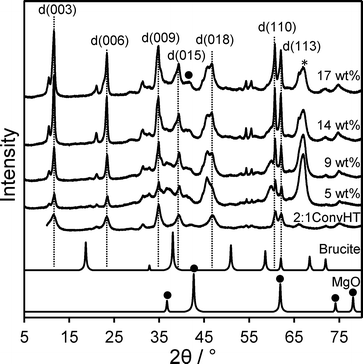 | ||
Fig. 1 XRD patterns for Mg–HT/Al2O3 series as a function of bulk Mg loading alongside 2![[thin space (1/6-em)]](https://www.rsc.org/images/entities/char_2009.gif) : :![[thin space (1/6-em)]](https://www.rsc.org/images/entities/char_2009.gif) 1ConvHT reference (* indicates parent Al2O3 and ● MgO). 1ConvHT reference (* indicates parent Al2O3 and ● MgO). | ||
| Mg loadinga/wt% | HT crystallite sizeb/nm | HT interlayer spacing d/nm | HT lattice parameter a/Å | Mg![[thin space (1/6-em)]](https://www.rsc.org/images/entities/char_2009.gif) : :![[thin space (1/6-em)]](https://www.rsc.org/images/entities/char_2009.gif) Al ratioc Al ratioc |
|---|---|---|---|---|
| a Bulk content from EDX. b XRD line broadening from Scherrer equation. c Calculated from Vegard's law. | ||||
| 5 | 27 ± 2.2 | 0.76 | 3.046 | 1.79![[thin space (1/6-em)]](https://www.rsc.org/images/entities/char_2009.gif) : :![[thin space (1/6-em)]](https://www.rsc.org/images/entities/char_2009.gif) 1 1 |
| 9 | 33 ± 2.6 | 0.76 | 3.050 | 1.90![[thin space (1/6-em)]](https://www.rsc.org/images/entities/char_2009.gif) : :![[thin space (1/6-em)]](https://www.rsc.org/images/entities/char_2009.gif) 1 1 |
| 14 | 36 ± 2.9 | 0.76 | 3.052 | 2.13![[thin space (1/6-em)]](https://www.rsc.org/images/entities/char_2009.gif) : :![[thin space (1/6-em)]](https://www.rsc.org/images/entities/char_2009.gif) 1 1 |
| 17 | 31 ± 2.5 | 0.77 | 3.051 | 2.08![[thin space (1/6-em)]](https://www.rsc.org/images/entities/char_2009.gif) : :![[thin space (1/6-em)]](https://www.rsc.org/images/entities/char_2009.gif) 1 1 |
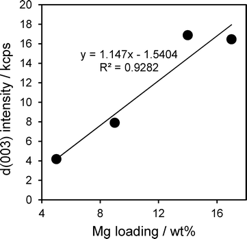
The intensity of hydrotalcite reflections increased linearly with Mg loading across the Mg–HT/Al2O3 series (Fig. 2), indicating that magnesium is exclusively incorporated into hydrotalcite phases and not e.g. undesired brucite or additional MgO. The relative intensities of hydrotalcite reflections from all the Mg–HT/Al2O3 materials were very similar to that of the 2![[thin space (1/6-em)]](https://www.rsc.org/images/entities/char_2009.gif) :
:![[thin space (1/6-em)]](https://www.rsc.org/images/entities/char_2009.gif) 1ConvHT reference, indicating they possess similar, three-dimensional crystallite morphologies (Table S1†).
1ConvHT reference, indicating they possess similar, three-dimensional crystallite morphologies (Table S1†).
In order to calculate the composition of hydrotalcite present within our Mg–HT/Al2O3 series, Vegard's law was first applied to quantify the relationship between the lattice parameter and Mg:Al ratio of pure, nanocrystalline hydrotalcites prepared via conventional co-precipitation (0.5![[thin space (1/6-em)]](https://www.rsc.org/images/entities/char_2009.gif) :
:![[thin space (1/6-em)]](https://www.rsc.org/images/entities/char_2009.gif) 1ConvHT–2
1ConvHT–2![[thin space (1/6-em)]](https://www.rsc.org/images/entities/char_2009.gif) :
:![[thin space (1/6-em)]](https://www.rsc.org/images/entities/char_2009.gif) 1ConvHT).20 As anticipated, the bulk Mg
1ConvHT).20 As anticipated, the bulk Mg![[thin space (1/6-em)]](https://www.rsc.org/images/entities/char_2009.gif) :
:![[thin space (1/6-em)]](https://www.rsc.org/images/entities/char_2009.gif) Al atomic ratio determined by EDX varied linearly with lattice parameter for the reference materials (Fig. 3).58 This relationship was utilised in conjunction with the XRD-derived lattice parameters from Table 1 to calculate the nominal Mg
Al atomic ratio determined by EDX varied linearly with lattice parameter for the reference materials (Fig. 3).58 This relationship was utilised in conjunction with the XRD-derived lattice parameters from Table 1 to calculate the nominal Mg![[thin space (1/6-em)]](https://www.rsc.org/images/entities/char_2009.gif) :
:![[thin space (1/6-em)]](https://www.rsc.org/images/entities/char_2009.gif) Al ratio within the hydrotalcite phase for each Mg–HT/Al2O3 sample without interference from the alumina support. The resulting Mg
Al ratio within the hydrotalcite phase for each Mg–HT/Al2O3 sample without interference from the alumina support. The resulting Mg![[thin space (1/6-em)]](https://www.rsc.org/images/entities/char_2009.gif) :
:![[thin space (1/6-em)]](https://www.rsc.org/images/entities/char_2009.gif) Al ratios for Mg–HT/Al2O3 show only a small increase with Mg content, remaining close to the 2
Al ratios for Mg–HT/Al2O3 show only a small increase with Mg content, remaining close to the 2![[thin space (1/6-em)]](https://www.rsc.org/images/entities/char_2009.gif) :
:![[thin space (1/6-em)]](https://www.rsc.org/images/entities/char_2009.gif) 1 ratio most commonly observed for co-precipitated hydrotalcites wherein crystallites are most ordered possessing a honeycomb structure with each Mg2+ ion surrounded by three Mg2+ and three Al3+ octahedra, and each Al3+ ion surrounded by six Mg2+ octahedra.59 This equates to a molecular formula of [Mg0.66Al0.33(OH)2]0.33+((CO32−)0.17)·mH2O. Since hydrotalcite compositions remains essentially unchanged across our Mg–HT/Al2O3 series, consecutive Mg(OCH3)2 impregnation cycles afford a simple means to tune the density of hydrotalcite crystallites, independent of their size, local interlayer spacing or surface basicity.
1 ratio most commonly observed for co-precipitated hydrotalcites wherein crystallites are most ordered possessing a honeycomb structure with each Mg2+ ion surrounded by three Mg2+ and three Al3+ octahedra, and each Al3+ ion surrounded by six Mg2+ octahedra.59 This equates to a molecular formula of [Mg0.66Al0.33(OH)2]0.33+((CO32−)0.17)·mH2O. Since hydrotalcite compositions remains essentially unchanged across our Mg–HT/Al2O3 series, consecutive Mg(OCH3)2 impregnation cycles afford a simple means to tune the density of hydrotalcite crystallites, independent of their size, local interlayer spacing or surface basicity.
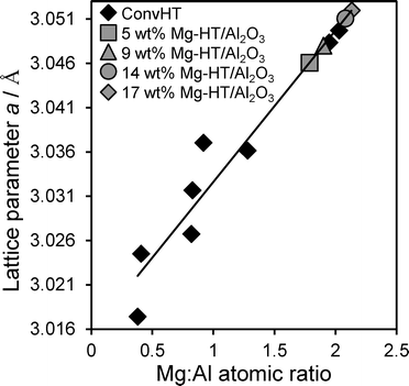 | ||
Fig. 3 Lattice parameter versus experimental Mg![[thin space (1/6-em)]](https://www.rsc.org/images/entities/char_2009.gif) : :![[thin space (1/6-em)]](https://www.rsc.org/images/entities/char_2009.gif) Al atomic ratio for co-precipitated Mg–Al hydrotalcites (ConvHTs), and theoretical Mg Al atomic ratio for co-precipitated Mg–Al hydrotalcites (ConvHTs), and theoretical Mg![[thin space (1/6-em)]](https://www.rsc.org/images/entities/char_2009.gif) : :![[thin space (1/6-em)]](https://www.rsc.org/images/entities/char_2009.gif) Al ratio derived for Mg–HT/Al2O3. Al ratio derived for Mg–HT/Al2O3. | ||
N2 porosimetry (Fig. S2†) reveals the BET surface areas Mg–HT/Al2O3 are comparable to the alumina support for low Mg loadings, but decrease >9 wt% Mg, although still twice that of the pure 2![[thin space (1/6-em)]](https://www.rsc.org/images/entities/char_2009.gif) :
:![[thin space (1/6-em)]](https://www.rsc.org/images/entities/char_2009.gif) 1ConvHT (Table 2). The BJH pore volumes for the Mg–HT/Al2O3 series are significantly higher than the parent alumina support, but fall likewise fall at high Mg loadings. We hypothesise that hydrotalcite crystallites initially nucleate widely spaced over the alumina surface, creating intercrystallite mesoporous voids; as the number of (similar sized) hydrotalcite crystallites rises with consecutive impregnation cycles, these interparticle voids are eliminated. The mean pore diameter may also rise due to blockage of micro- and smaller mesopores in the alumina support by preferential hydrotalcite crystallisation at such pore entrances. Thermal analysis of Mg–HT/Al2O3 samples showed the expected weight losses due to desorption of interlayer hydroxide anions (Fig. S3†) which increased with Mg loading consistent with their greater hydrotalcite content seen by XRD.
1ConvHT (Table 2). The BJH pore volumes for the Mg–HT/Al2O3 series are significantly higher than the parent alumina support, but fall likewise fall at high Mg loadings. We hypothesise that hydrotalcite crystallites initially nucleate widely spaced over the alumina surface, creating intercrystallite mesoporous voids; as the number of (similar sized) hydrotalcite crystallites rises with consecutive impregnation cycles, these interparticle voids are eliminated. The mean pore diameter may also rise due to blockage of micro- and smaller mesopores in the alumina support by preferential hydrotalcite crystallisation at such pore entrances. Thermal analysis of Mg–HT/Al2O3 samples showed the expected weight losses due to desorption of interlayer hydroxide anions (Fig. S3†) which increased with Mg loading consistent with their greater hydrotalcite content seen by XRD.
![[thin space (1/6-em)]](https://www.rsc.org/images/entities/char_2009.gif) :
:![[thin space (1/6-em)]](https://www.rsc.org/images/entities/char_2009.gif) 1ConvHT and parent Al2O3 support references
1ConvHT and parent Al2O3 support references
| Material | BET surface area/m2 g−1 | BJH pore volume/cm3 g−1 | Average BJH pore diameter/nm |
|---|---|---|---|
| Al2O3 | 110 ± 11 | 0.23 ± 0.02 | 1.2 ± 0.1 |
| 5 wt% | 119 ± 12 | 0.81 ± 0.10 | 21 ± 3 |
| 9 wt% | 113 ± 11 | 0.75 ± 0.09 | 26 ± 5 |
| 14 wt% | 90 ± 9 | 0.59 ± 0.07 | 26 ± 5 |
| 17 wt% | 88 ± 9 | 0.57 ± 0.07 | 17 ± 2 |
| 2:1ConvHT | 48 ± 5 | 0.21 ± 0.01 | 3.4 ± 0.4 |
Surface basicity of Mg–HT/Al2O3 was assessed via CO2 TPD of the pre-saturated materials. Fig. 4 shows that all supported hydrotalcites possess significantly lower base site densities than the co-precipitated 2![[thin space (1/6-em)]](https://www.rsc.org/images/entities/char_2009.gif) :
:![[thin space (1/6-em)]](https://www.rsc.org/images/entities/char_2009.gif) 1ConvHT reference. However, in contrast to the pure hydrotalcite which only exhibits a single well-defined desorption peak ~350 °C, all the Mg–HT/Al2O3 samples display two distinct CO2 desorptions. The low temperature desorption (centred ~300 °C) is assigned to bicarbonate species formed at surface hydroxide anions exposed on the external surface of hydrotalcite crystallites and the parent alumina.60,61 These are weaker bases than the interlayer hydroxide anions,62 hence the higher temperature feature (>370 °C) is assigned to CO2 bound between the brucite-like sheets.63 The desorption areas, and hence densities, of both types of base sites present within Mg–HT/Al2O3 increase with Mg content (Table 3), consistent with increased hydrotalcite formation apparent by XRD and TGA. The desorption peak maximum for interlayer bicarbonate shifts to lower temperature with increasing Mg content, converging towards that of the 2
1ConvHT reference. However, in contrast to the pure hydrotalcite which only exhibits a single well-defined desorption peak ~350 °C, all the Mg–HT/Al2O3 samples display two distinct CO2 desorptions. The low temperature desorption (centred ~300 °C) is assigned to bicarbonate species formed at surface hydroxide anions exposed on the external surface of hydrotalcite crystallites and the parent alumina.60,61 These are weaker bases than the interlayer hydroxide anions,62 hence the higher temperature feature (>370 °C) is assigned to CO2 bound between the brucite-like sheets.63 The desorption areas, and hence densities, of both types of base sites present within Mg–HT/Al2O3 increase with Mg content (Table 3), consistent with increased hydrotalcite formation apparent by XRD and TGA. The desorption peak maximum for interlayer bicarbonate shifts to lower temperature with increasing Mg content, converging towards that of the 2![[thin space (1/6-em)]](https://www.rsc.org/images/entities/char_2009.gif) :
:![[thin space (1/6-em)]](https://www.rsc.org/images/entities/char_2009.gif) 1ConvHT for the 17 wt% Mg–HT/Al2O3 sample. We attribute the higher initial desorption temperature to contributions from a disordered MgO phase at the alumina interface as evidenced by XPS in the following section.
1ConvHT for the 17 wt% Mg–HT/Al2O3 sample. We attribute the higher initial desorption temperature to contributions from a disordered MgO phase at the alumina interface as evidenced by XPS in the following section.
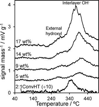 | ||
Fig. 4 CO2 TPD profiles for Mg–HT/Al2O3 series and 2![[thin space (1/6-em)]](https://www.rsc.org/images/entities/char_2009.gif) : :![[thin space (1/6-em)]](https://www.rsc.org/images/entities/char_2009.gif) 1 ConvHT reference as a function of bulk Mg loading. 1 ConvHT reference as a function of bulk Mg loading. | ||
![[thin space (1/6-em)]](https://www.rsc.org/images/entities/char_2009.gif) :
:![[thin space (1/6-em)]](https://www.rsc.org/images/entities/char_2009.gif) 1ConvHT reference determined via CO2 TPD analysis
1ConvHT reference determined via CO2 TPD analysis
| Material | External density/g−1 | External Tmaxa/°C | Interlayer density/g−1 | Interlayer Tmaxa/°C | Total density/g−1 |
|---|---|---|---|---|---|
| a Experimental error ±0.2 °C. | |||||
| 5 wt% | 1.03 × 10¹⁸ | 283.9 | 3.66 × 10¹⁸ | 397.63 | 4.69 × 10¹⁸ |
| 9 wt% | 1.12 × 10¹⁸ | 297.1 | 5.30 × 10¹⁸ | 397.2 | 6.43 × 10¹⁸ |
| 14 wt% | 1.63 × 10¹⁸ | 314.0 | 1.09 × 10¹⁹ | 391.5 | 1.25 × 10¹⁹ |
| 17 wt% | 3.77 × 10¹⁸ | 291.0 | 1.82 × 10¹⁹ | 374.6 | 2.20 × 10¹⁹ |
2![[thin space (1/6-em)]](https://www.rsc.org/images/entities/char_2009.gif) : :![[thin space (1/6-em)]](https://www.rsc.org/images/entities/char_2009.gif) 1ConvHT 1ConvHT |
— | — | 8.55 × 10¹⁹ | 349.8 | 8.55 × 10¹⁹ |
Further insight into the Mg–HT/Al2O3 surface composition was obtained from XPS. Fig. 5 shows the resulting background subtracted, fitted Al 2p and Mg 2s XP spectra as a function of bulk Mg content, alongside pure alumina and MgO reference compounds. Considering the Al 2p spectra of the parent alumina first, two distinct sets of spin–orbit split doublets are apparent, with 2p3/2 binding energies (BE) of 73.8 and 74.7 eV, attributed to respective octahedral and tetrahedral Al3+ sites within the underlying γ-Al2O3 support,64 in the expected ~2![[thin space (1/6-em)]](https://www.rsc.org/images/entities/char_2009.gif) :
:![[thin space (1/6-em)]](https://www.rsc.org/images/entities/char_2009.gif) 1 ratio for a defective spinel structure.65 Magnesium impregnation results in the appearance of a new doublet at 73.5 eV, whose intensity increase monotonically with Mg loading and we assign to the hydrotalcite phase. Coincident attenuation of alumina features demonstrates that hydrotalcite crystallites coat the support surface, presumably via the dissolution and reaction of aluminium cations as previously hypothesised from EXAFS studies.50,51 The Mg 2s XP spectra of Mg–HT/Al2O3 materials reveal a high BE component at 87.9 eV characteristic of MgO,65 and a second component at 88.5 eV which grows with Mg loading and is likewise assigned to hydrotalcite formation.
1 ratio for a defective spinel structure.65 Magnesium impregnation results in the appearance of a new doublet at 73.5 eV, whose intensity increase monotonically with Mg loading and we assign to the hydrotalcite phase. Coincident attenuation of alumina features demonstrates that hydrotalcite crystallites coat the support surface, presumably via the dissolution and reaction of aluminium cations as previously hypothesised from EXAFS studies.50,51 The Mg 2s XP spectra of Mg–HT/Al2O3 materials reveal a high BE component at 87.9 eV characteristic of MgO,65 and a second component at 88.5 eV which grows with Mg loading and is likewise assigned to hydrotalcite formation.
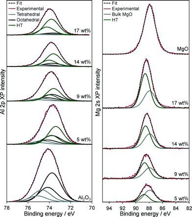 | ||
| Fig. 5 (Left) Al 2p and (Right) Mg 2s XP spectra of Mg–HT/Al2O3 series as a function of bulk Mg loading and pure Al2O3 and MgO references. | ||
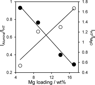
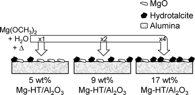
Attenuation of the underlying alumina XP signal at 74.7 eV relative to the summed hydrotalcite (Al 2p3/2 73.5 eV and Mg 2 s 88.5 eV) XP signals is directly proportional to the Mg content (Fig. 6), indicating that successive magnesium additions produce new hydrotalcite crystallites over exposed patches of the support, resulting in a conformal coating, rather than a rough/porous three-dimensional film. This is consistent with the loss of (intercrystallite) mesopore voids at higher Mg loadings seen in Table 2. The proportion of surface magnesium incorporated into the [Mg0.66Al0.33(OH)2]0.33+((CO32−)0.17)·mH2O hydrotalcite phase thus rises from 38% to 64% across the Mg–HT/Al2O3 series. Attenuation of the alumina XP signal can also be used to estimate the fractional coverage of the hydrotalcite coating. Since the mean hydrotalcite crystallite size of ~30 nm is sufficient to fully screen any contribution from the underlying support, the remaining alumina XP signal detected must arise from exposed areas. The surface coverage of the 17 wt% Mg–HT/Al2O3 hydrotalcite coating is around 0.55 of a monolayer, similar to that estimated from the parent alumina surface area and the surface density of Mg atoms within a 2![[thin space (1/6-em)]](https://www.rsc.org/images/entities/char_2009.gif) :
:![[thin space (1/6-em)]](https://www.rsc.org/images/entities/char_2009.gif) 1 Mg–Al hydrotalcite phase (Table S2†). Scheme 1 summarises the proposed growth mode of the hydrotalcite coating over alumina.
1 Mg–Al hydrotalcite phase (Table S2†). Scheme 1 summarises the proposed growth mode of the hydrotalcite coating over alumina.
Catalytic transesterification
The efficacy of our Mg–HT/Al2O3 materials for FAME production was evaluated via the transesterification of increasingly bulky TAGs, from tributyrin (C4) through to glyceryl trioleate (C18), with methanol under mild conditions. Reaction profiles for resulting FAME production are shown in Fig. 7 for the highest loading 14 wt% and 17 wt% Mg–HT/Al2O3, alongside the conventionally prepared 2![[thin space (1/6-em)]](https://www.rsc.org/images/entities/char_2009.gif) :
:![[thin space (1/6-em)]](https://www.rsc.org/images/entities/char_2009.gif) 1ConvHT material. Two reaction regimes were observed for all catalysts and substrates; rapid esterification during the initial 50–200 min of reaction wherein the FAME yield increases linearly with time, followed by a slower phase with TAG conversion reaching a plateau between 26–55%.
1ConvHT material. Two reaction regimes were observed for all catalysts and substrates; rapid esterification during the initial 50–200 min of reaction wherein the FAME yield increases linearly with time, followed by a slower phase with TAG conversion reaching a plateau between 26–55%.
 | ||
Fig. 7 FAME productivity via the transesterification of tributyrin, tricaprylin and triolein with methanol at 60 °C over Mg–HT/Al2O3 and 2![[thin space (1/6-em)]](https://www.rsc.org/images/entities/char_2009.gif) : :![[thin space (1/6-em)]](https://www.rsc.org/images/entities/char_2009.gif) 1ConvHT catalysts. 1ConvHT catalysts. | ||
Table 4 compares the initial rates of TAG conversion (determined directly by GC analysis and not inferred from FAME yields) and limiting conversion and selectivity after 24 h reaction across the Mg–HT/Al2O3 series. Note that the low loading 5 wt% and 9 wt% Mg–HT/Al2O3 were not tested in triolein transesterification since their low base site densities prohibited accurate conversion measurements during the early stage of reaction. The absolute initial rate increased almost linearly with Mg loading, closely mirroring the rise in total and interlayer base site densities. Despite the 50 mg 2![[thin space (1/6-em)]](https://www.rsc.org/images/entities/char_2009.gif) :
:![[thin space (1/6-em)]](https://www.rsc.org/images/entities/char_2009.gif) 1ConvHT catalyst charge comprising pure hydrotalcite with a high base site density, the associated initial rate of TAG conversion was comparable to that of the 17 wt% Mg–HT/Al2O3 catalyst. Resulting Turnover Frequencies for the coated aluminas are thus far superior to that of the co-precipitated reference catalyst, offering three- (C4/C8) to ten-fold (C18) rate enhancements (Fig. 8). This indicates that the majority of active sites in the 2
1ConvHT catalyst charge comprising pure hydrotalcite with a high base site density, the associated initial rate of TAG conversion was comparable to that of the 17 wt% Mg–HT/Al2O3 catalyst. Resulting Turnover Frequencies for the coated aluminas are thus far superior to that of the co-precipitated reference catalyst, offering three- (C4/C8) to ten-fold (C18) rate enhancements (Fig. 8). This indicates that the majority of active sites in the 2![[thin space (1/6-em)]](https://www.rsc.org/images/entities/char_2009.gif) :
:![[thin space (1/6-em)]](https://www.rsc.org/images/entities/char_2009.gif) 1ConvHT reference do not participate in esterification, even though individual crystallites are significantly more highly dispersed (6 nm) and afford a far higher density of base sites accessible by CO2 than those in the coated aluminas (~30 nm). Nanocrystallite aggregation during the conventional hydrotalcite preparation seems the likely culprit for its poorer performance.
1ConvHT reference do not participate in esterification, even though individual crystallites are significantly more highly dispersed (6 nm) and afford a far higher density of base sites accessible by CO2 than those in the coated aluminas (~30 nm). Nanocrystallite aggregation during the conventional hydrotalcite preparation seems the likely culprit for its poorer performance.
![[thin space (1/6-em)]](https://www.rsc.org/images/entities/char_2009.gif) :
:![[thin space (1/6-em)]](https://www.rsc.org/images/entities/char_2009.gif) 1ConvHT catalysts as a function of bulk Mg loading and TAG chain length
1ConvHT catalysts as a function of bulk Mg loading and TAG chain length
| C4 TAG | C8 TAG | C18 TAG | |||||||
|---|---|---|---|---|---|---|---|---|---|
| Initial rate/mmol min−1 g−1 | Conversiona/% | FAME selectivitybc/% | Initial rate/mmol min−1 g−1 | Conversiona/% | FAME selectivitybc/% | Initial rate/mmol min−1 g−1 | Conversiona/% | FAME selectivitybc/% | |
a GC analysis of TAG after 24 h reaction at 60 °C.
b 0.05 g catalyst, and MeOH![[thin space (1/6-em)]](https://www.rsc.org/images/entities/char_2009.gif) : :![[thin space (1/6-em)]](https://www.rsc.org/images/entities/char_2009.gif) TAG = 30 TAG = 30![[thin space (1/6-em)]](https://www.rsc.org/images/entities/char_2009.gif) : :![[thin space (1/6-em)]](https://www.rsc.org/images/entities/char_2009.gif) 1.
c GC analysis, error of 1.5%. 1.
c GC analysis, error of 1.5%.
|
|||||||||
| 2:1ConvHT | 0.78 ± 0.01 | 42 | 43 | 0.42 ± 0.13 | 30 | 54 | 0.026 ± 0.01 | 16 | 67 |
| 5 wt% Mg | 0.15 ± 0.01 | 13 | 7 | 0.10 ± 0.02 | 5 | 14 | n/a | n/a | n/a |
| 9 wt% Mg | 0.21 ± 0.03 | 14 | 8 | 0.16 ± 0.03 | 5 | 18 | n/a | n/a | n/a |
| 14 wt% Mg | 0.40 ± 0.02 | 19 | 14 | 0.30 ± 0.05 | 10 | 25 | 0.024 ± 0.002 | 4 | 26 |
| 17 wt% Mg | 0.66 ± 0.03 | 25 | 20 | 0.49 ± 0.09 | 15 | 40 | 0.042 ± 0.004 | 6 | 42 |
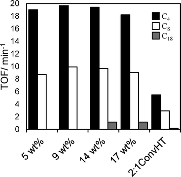 | ||
Fig. 8 TOF values for Mg–HT/Al2O3 catalysts compared to a 2![[thin space (1/6-em)]](https://www.rsc.org/images/entities/char_2009.gif) : :![[thin space (1/6-em)]](https://www.rsc.org/images/entities/char_2009.gif) 1ConvHT reference catalyst as a function of bulk Mg loading and TAG chain length. 1ConvHT reference catalyst as a function of bulk Mg loading and TAG chain length. | ||
TOFs for Mg–HT/Al2O3 were almost identical whether calculated per base site or per interlayer base site, and crucially, were independent of Mg loading for all TAGs (Fig. 8). The latter observation is consistent with our model of a two-dimensional (nanocrystalline) hydrotalcite coating spreading over the alumina support, rather of than three-dimensional growth at higher Mg loadings which would impede TAG diffusion and access to active base sites lowering the apparent TOFs. Indeed, absolute TOF values for the Mg–HT/Al2O3 catalysts are comparable to those recently reported employing a (pure) macroporous Mg–Al hydrotalcite to overcome mass-transport limitations even for bulky triglycerides.20 Since the proportion of surface MgO and hydrotalcite varies with loading (Fig. 6), the observation of a common TOF value for the C4 and C8 TAGs suggests either both phases have the same intrinsic activity towards transesterification, or that only the hydrotalcite coating participates in reaction; as mentioned above, the absolute TOF values of 10–20 min−1 are in excellent agreement with literature values for hydrotalcites, and an order of magnitude greater than expected for MgO,25,66,67 hence we favour the latter hypothesis. Observation of a constant TOF when normalising rates to the (more strongly basic) interlayer OH− density suggests that these are the active sites responsible for transesterification, rather than weaker hydroxyls on the external surface of hydrotalcite crystallites (for which a volcano dependence of TOF on loading is obtained).
This conclusion is also in accordance with the other key finding from Fig. 8, namely the decrease in TOF for each Mg–HT/Al2O3 with alkyl chain length from 19 (C4) > 9 (C8) > 1 (C18); access to base sites within the microporous interlayers is expected to fall significantly as the molecular size of TAGs increases.
Selectivity to the desired FAME product increases with TAG conversion in all cases, as expected, since more active catalysts are likely to favour esterification of the diglyceride (DAG) and monoglyceride (MAG) intermediates (Fig. S4†). The lower selectivity of the Mg–HT/Al2O3 catalysts simply reflects their lower conversions relative to conventional, pure hydrotalcites (unsurprisingly since they contain far fewer base sites), and hence greater yield of intermediate DAGs and MAGs, which are precursors to the desired FAME product. Hence lower selectivity is not a result of alternative side-products, or subsequent reaction of FAME, but merely that, as for any sequential reaction, the higher the initial TAG conversion (and thus greater concentration of reactive intermediates), the greater probability that DAG and MAG liberated into the reaction media will compete effectively with the TAG feedstock to re-adsorb and further react at surface base sites – the pre-requisite for FAME production. However, Table 4 also reveals that for all catalysts FAME selectivity increases with TAG chain length, e.g. from 20% to 42% for the 17 wt% Mg–HT/Al2O3. We suggest this relates to the increasingly poor solubility of the heavier DAG/MAG intermediates in the methanol–butanol solvent, and hence longer residence time within the HT interlayer of crystallite edges and consequent propensity to undergo consecutive esterification reactions. In contrast, the highly soluble di- and monobutyrin are readily solubilised in the alcoholic bulk medium resulting in poor FAME selectivities.
Stability of the active HT phase within Mg–HT/Al2O3 catalysts was assessed by bulk and surface analysis following recovery via hot filtration and methanol washing (50 cm3) after a 24 h tributyrin transesterification. EDX showed no change in the Mg![[thin space (1/6-em)]](https://www.rsc.org/images/entities/char_2009.gif) :
:![[thin space (1/6-em)]](https://www.rsc.org/images/entities/char_2009.gif) Al ratios for any loading, suggesting minimal Mg leaching during reaction. XRD revealed the hydrotalcite structure was preserved in all cases with negligible change in the interlayer spacing post-reaction, although crystallite sizes decreased slightly (Fig. S5†). The HT lattice parameter also exhibited a small decrease from e.g. 2.08
Al ratios for any loading, suggesting minimal Mg leaching during reaction. XRD revealed the hydrotalcite structure was preserved in all cases with negligible change in the interlayer spacing post-reaction, although crystallite sizes decreased slightly (Fig. S5†). The HT lattice parameter also exhibited a small decrease from e.g. 2.08![[thin space (1/6-em)]](https://www.rsc.org/images/entities/char_2009.gif) :
:![[thin space (1/6-em)]](https://www.rsc.org/images/entities/char_2009.gif) 1 to 1.87
1 to 1.87![[thin space (1/6-em)]](https://www.rsc.org/images/entities/char_2009.gif) :
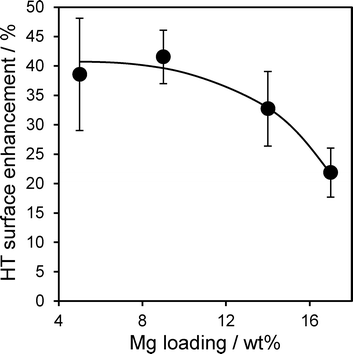
:![[thin space (1/6-em)]](https://www.rsc.org/images/entities/char_2009.gif) 1 for 17 wt% Mg–HT/Al2O3 suggesting a small amount of aluminium was incorporated in the hydrotalcite coating during esterification. The latter conclusion is supported by the higher intensity of HT versus alumina reflections post-reaction, whose ratio increases by ~120 ± 30% across the coated aluminas. This surprising observation that the spent catalyst contains more of the desired active hydrotalcite phase than the fresh material was further supported by XPS. Fig. 9 plots the mean change in Mg 2s and Al 2p derived HT surface populations (as a function of Mg loading), following tributryin esterification. All Mg–HT/Al2O3 catalysts expose significantly more hydrotalcite post-reaction, at the expense of MgO and alumina, which we suggest react in situ via ion-exchange under the mild, solvothermal conditions. This enhancement is less for higher Mg loadings, wherein the freshly prepared surface HT coatings already encapsulate more of the alumina support (Fig. 6).
1 for 17 wt% Mg–HT/Al2O3 suggesting a small amount of aluminium was incorporated in the hydrotalcite coating during esterification. The latter conclusion is supported by the higher intensity of HT versus alumina reflections post-reaction, whose ratio increases by ~120 ± 30% across the coated aluminas. This surprising observation that the spent catalyst contains more of the desired active hydrotalcite phase than the fresh material was further supported by XPS. Fig. 9 plots the mean change in Mg 2s and Al 2p derived HT surface populations (as a function of Mg loading), following tributryin esterification. All Mg–HT/Al2O3 catalysts expose significantly more hydrotalcite post-reaction, at the expense of MgO and alumina, which we suggest react in situ via ion-exchange under the mild, solvothermal conditions. This enhancement is less for higher Mg loadings, wherein the freshly prepared surface HT coatings already encapsulate more of the alumina support (Fig. 6).
In light of the preceding observation that XPS indicates no degradation of the hydrotalcite coating in spent catalysts, we examine the catalytic stability of the 17 wt% Mg–HT/Al2O3 material towards tributyrin transesterification under repeated re-use (Fig. 10). The spent catalyst was simply filtered and washed with 80 cm−3 of methanol after each reaction to remove any reversibly adsorbed TAG or products, dried at 80 °C in air, and then re-introduced to the reactor with a fresh tributyrin/methanol charge without further pretreatment. This rapid, low cost and energy efficient regeneration protocol proved effect, with only a 10% drop activity after the first reaction, and no further change from second to third recycles. We attribute this small, one-off drop to site-blocking of the strongest base sites by strongly bound carboxylate residues which cannot be removed by our extremely mild solvent wash between cycles. It is likely that recalcination/rehydration of spent catalysts would suffice to fully regenerate this small deactivation.
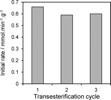 | ||
| Fig. 10 Activity of 17 wt% Mg–HT/Al2O3 catalyst following the consecutive transesterification of tributyrin with methanol at 60 °C highlighting excellent stability under re-use. | ||
Conclusions
A uniform and tunable coating of Mg–Al hydrotalcite nanocrystallites has been grown over amorphous alumina via an environmentally-friendly route employing impregnation and subsequent hydrothermal processing of magnesium methoxide, without recourse to alkali- or nitrogen-containing precursors. The hydrotalcite coating has a constant Mg![[thin space (1/6-em)]](https://www.rsc.org/images/entities/char_2009.gif) :
:![[thin space (1/6-em)]](https://www.rsc.org/images/entities/char_2009.gif) Al stoichiometry of 2
Al stoichiometry of 2![[thin space (1/6-em)]](https://www.rsc.org/images/entities/char_2009.gif) :
:![[thin space (1/6-em)]](https://www.rsc.org/images/entities/char_2009.gif) 1 and interlayer spacing of ~1 nm, and wets the alumina support with a coverage proportional to the magnesium concentration. Chemisorption measurements reveal two distinct base sites; minority, weakly basic surface hydroxyls, and majority, medium basicity interlayer hydroxide anions. Turnover frequencies for C4–C18 triglyceride tranesterification with methanol over Mg–HT/Al2O3 are superior to those of conventional (pure) hydrotalcites prepared via co-precipitation, particularly for the long chain triolein naturally occurring at 8–15% in Jatropha curcas seed oil,68,69 highlighting the potential application of these hydrotalcite coatings in biodiesel production from sustainable biomass. This enhanced reactivity is attributed to the high dispersion of hydrotalcite nanocrystallites over the parent alumina surface and associated intercrystallite mesopore voids, which eliminate mass-transport barriers to the diffusion of bulky TAGs prevalent within co-precipitated hydrotalcite catalysts. Indeed the TOFs observed herein for Mg–HT/Al2O3 catalysts are comparable to those for macroporous hydrotalcites20 synthesised through less cost-effective and more complex hard-templating protocols employing sacrificial polystyrene nanospheres. In summary, we have developed a simple, low cost route to depositing crystalline hydrotalcite coatings over high area alumina from benign precursors that affords highly active solid base catalysts for FAME production under mild reaction conditions.
1 and interlayer spacing of ~1 nm, and wets the alumina support with a coverage proportional to the magnesium concentration. Chemisorption measurements reveal two distinct base sites; minority, weakly basic surface hydroxyls, and majority, medium basicity interlayer hydroxide anions. Turnover frequencies for C4–C18 triglyceride tranesterification with methanol over Mg–HT/Al2O3 are superior to those of conventional (pure) hydrotalcites prepared via co-precipitation, particularly for the long chain triolein naturally occurring at 8–15% in Jatropha curcas seed oil,68,69 highlighting the potential application of these hydrotalcite coatings in biodiesel production from sustainable biomass. This enhanced reactivity is attributed to the high dispersion of hydrotalcite nanocrystallites over the parent alumina surface and associated intercrystallite mesopore voids, which eliminate mass-transport barriers to the diffusion of bulky TAGs prevalent within co-precipitated hydrotalcite catalysts. Indeed the TOFs observed herein for Mg–HT/Al2O3 catalysts are comparable to those for macroporous hydrotalcites20 synthesised through less cost-effective and more complex hard-templating protocols employing sacrificial polystyrene nanospheres. In summary, we have developed a simple, low cost route to depositing crystalline hydrotalcite coatings over high area alumina from benign precursors that affords highly active solid base catalysts for FAME production under mild reaction conditions.
Acknowledgements
We thank the EPSRC (EP/G007594/3) for financial support and a Leadership Fellowship (AFL) and studentship (JJC), and the Royal Society for the award of an Industry Fellowship (KW).Notes and references
- International Energy Outlook 2013, Report DOE/EIA-0484(2013), 2013 Search PubMed.
- N. Armaroli and V. Balzani, Angew. Chem., Int. Ed., 2007, 46, 52–66 CrossRef CAS PubMed.
- R. Luque, L. Herrero-Davila, J. M. Campelo, J. H. Clark, J. M. Hidalgo, D. Luna, J. M. Marinas and A. A. Romero, Energy Environ. Sci., 2008, 1, 542–564 CAS.
- X. Y. Yan, O. R. Inderwildi and D. A. King, Energy Environ. Sci., 2010, 3, 190–197 CAS.
- W. M. J. Achten, L. Verchot, Y. J. Franken, E. Mathijs, V. P. Singh, R. Aerts and B. Muys, Biomass Bioenergy, 2008, 32, 1063–1084 CrossRef CAS PubMed.
- G. Knothe, Top. Catal., 2010, 53, 714–720 CrossRef CAS.
- M. J. Climent, A. Corma, S. Iborra and A. Velty, J. Catal., 2004, 221, 474–482 CrossRef CAS PubMed.
- U. Constantino, F. Marmottini, M. Nocchetti and R. Vivani, Eur. J. Inorg. Chem., 1998, 1439–1446 CrossRef.
- K. Narasimharao, A. Lee and K. Wilson, J. Biobased Mater. Bioenergy, 2007, 1, 19–30 Search PubMed.
- M. R. Othman, Z. Helwani, Martunus and W. J. N. Fernando, Appl. Organomet. Chem., 2009, 23, 335–346 CrossRef CAS.
- Y. Liu, E. Lotero, J. G. Goodwin and X. Mo, Appl. Catal., A, 2007, 33, 138–148 CrossRef PubMed.
- J. Geuens, J. M. Kremsner, B. A. Nebel, S. Schober, R. A. Dommisse, M. Mittelbach, S. Tavernier, C. O. Kappe and B. U. W. Maes, Energy Fuels, 2007, 22, 643–645 CrossRef.
- Jianbo, Zexue, Z. Tang and Enze, Ind. Eng. Chem. Res., 2004, 43, 7928–7931 CrossRef.
- G. Knothe, Fuel Process. Technol., 2005, 86, 1059–1070 CrossRef CAS PubMed.
- T. M. Mata, A. A. Martins and N. S. Caetano, Renewable Sustainable Energy Rev., 2010, 14, 217 CrossRef CAS PubMed.
- K. Wilson and A. F. Lee, Catal. Sci. Technol., 2012, 2, 884–897 CAS.
- K. N. Rao, A. F. Lee and K. Wilson, J. Biobased Mater. Bioenergy, 2007, 1, 19 Search PubMed.
- M. J. Kim, S. M. Park, D. R. Chang and G. Seo, Fuel Process. Technol., 2010, 91, 618–624 CrossRef CAS PubMed.
- Y. Xi and R. J. Davis, J. Catal., 2008, 254, 190–197 CrossRef CAS PubMed.
- J. J. Woodford, J.-P. Dacquin, K. Wilson and A. F. Lee, Energy Environ. Sci., 2012, 5, 6145–6150 CAS.
- D. G. Cantrell, L. J. Gillie, A. F. Lee and K. Wilson, Appl. Catal., A, 2005, 287, 183–190 CrossRef CAS PubMed.
- T. F. Dossin, M.-F. Reyniers, R. J. Berger and G. B. Marin, Appl. Catal., B, 2006, 67, 136–148 CrossRef CAS PubMed.
- R. S. Watkins, A. F. Lee and K. Wilson, Green Chem., 2004, 6, 335–340 RSC.
- K. Wilson, C. Hardacre, A. F. Lee, J. M. Montero and L. Shellard, Green Chem., 2008, 10, 654–659 RSC.
- J. M. Montero, P. Gai, K. Wilson and A. F. Lee, Green Chem., 2009, 11, 265–268 RSC.
- M. Verziu, B. Cojocaru, J. Hu, R. Richards, C. Ciuculescu, P. Filip and V. I. Parvulescu, Green Chem., 2008, 10, 373–381 RSC.
- M. C. G. Albuquerque, I. Jimenez-Urbistondo, J. Santamaria-Gonzalez, J. M. Merida-Robles, R. Moreno-Tost, E. Rodriguez-Castellon, A. Jimenez-Lopez, D. C. S. Azevedo, C. L. Cavalcante Jr. and P. Maireles-Torres, Appl. Catal., A, 2008, 334, 35–43 CrossRef CAS PubMed.
- H. A. Pearce and N. Sheppard, Surf. Sci., 1976, 59, 205–217 CrossRef CAS.
- H. Pines and W. O. Haag, J. Am. Chem. Soc., 1960, 82, 2471–2483 CrossRef CAS.
- B. R. Cuenya, Thin Solid Films, 2010, 518, 3127–3150 CrossRef CAS PubMed.
- C. M. A. Parlett, D. W. Bruce, N. S. Hondow, A. F. Lee and K. Wilson, ACS Catal., 2011, 1, 636–640 CrossRef CAS.
- J. M. Campelo, A. F. Lee, R. Luque, D. Luna, J. M. Marinas and A. A. Romero, Chem.–Eur. J., 2008, 14, 5988–5995 CrossRef CAS PubMed.
- N. F. Zheng and G. D. Stucky, J. Am. Chem. Soc., 2006, 128, 14278–14280 CrossRef CAS PubMed.
- M. Zabeti, W. M. A. Wan Daud and M. K. Aroua, Fuel Process. Technol., 2009, 90, 770–777 CrossRef CAS PubMed.
- I. Chorkendorff and J. W. Niemantsverdriet, Concepts of Modern Catalysis and Kinetics, Wiley-VCH, Germany, 2003 Search PubMed.
- F. Cavani, F. Trifirò and A. Vaccari, Catal. Today, 1991, 11, 173–301 CrossRef CAS.
- M. R. Othman, N. M. Rasid and W. J. N. Fernando, Chem. Eng. Sci., 2006, 61, 1555–1560 CrossRef CAS PubMed.
- I. Reyero, I. Velasco, O. Sanz, M. Montes, G. Arzamendi and L. M. Gandía, Catal. Today, 2013, 216, 211–219 CrossRef CAS PubMed.
- D. M. Alonso, R. Mariscal, M. L. Granados and P. Maireles-Torres, Catal. Today, 2009, 143, 167–171 CrossRef CAS PubMed.
- D.-W. Lee, Y.-M. Park and K.-Y. Lee, Catal. Surv. Asia, 2009, 13, 63–77 CrossRef CAS.
- M. Di Serio, R. Tesser, L. Casale, A. D'Angelo, M. Trifuoggi and E. Santacesaria, Top. Catal., 2010, 53, 811–819 CrossRef CAS.
- Y. C. Sharma, B. Singh and J. Korstad, Fuel, 2011, 90, 1309–1324 CrossRef CAS PubMed.
- A. A. Refaat, Int. J. Environ. Sci. Technol., 2011, 8, 203–221 CrossRef CAS.
- BASF AG, UK Patent, 1,462,059-60, 1973 Search PubMed.
- J. L. Paulhiac and O. Clause, J. Am. Chem. Soc., 1993, 115, 11602–11603 CrossRef CAS.
- Y. F. Gao, A. Nagai, Y. Masuda, F. Sato, W. S. Seo and K. Koumoto, Langmuir, 2006, 22, 3521–3527 CrossRef CAS PubMed.
- S. P. Newman, W. Jones, P. O'Connor and D. N. Stamires, J. Mater. Chem., 2002, 12, 153–155 RSC.
- S. Mitchell, T. Biswick, W. Jones, G. WIlliams and D. O'Hare, Green Chem., 2007, 9, 373–378 RSC.
- F. Kovanda, P. Masatova, P. Novotna and K. Jiratova, Clays Clay Miner., 2009, 57, 425–432 CrossRef CAS.
- T. P. Trainor, G. E. Brown Jr and G. A. Parks, J. Colloid Interface Sci., 2000, 231, 359–372 CrossRef CAS PubMed.
- J. B. D. Delacaillerie, M. Kermarec and O. Clause, J. Am. Chem. Soc., 1995, 117, 11471–11481 CrossRef.
- Y. Xi and R. J. Davis, J. Catal., 2009, 268, 307–317 CrossRef CAS PubMed.
- M. Behrens, S. Kißner, F. Girsgdies, I. Kasatkin, F. Hermerschmidt, K. Mette, H. Ruland, M. Muhler and R. Schlogl, Chem. Commun., 2011, 47, 1701–1703 RSC.
- C. J. Johnson and B. C. Kross, Am. J. Ind. Med., 1990, 18, 449–456 CrossRef CAS.
- K. Chibwe and W. Jones, J. Chem. Soc., Chem. Commun., 1989, 926 RSC.
- F. Cavani, F. Trifiro and A. Vaccari, Catal. Today, 1991, 11, 173–291 CrossRef CAS.
- S. Miyata, Clays Clay Miner., 1983, 31, 305–311 CAS.
- A. R. Denton and N. W. Ashcroft, Phys. Rev. A: At., Mol., Opt. Phys., 1991, 43, 3161–3164 CrossRef CAS.
- H. Pfeiffer, L. Martinez-dIcruz, E. Lima, J. Flores, M. A. Vera and J. S. Valente, J. Phys. Chem. C, 2010, 114, 8485–8492 CAS.
- M. A. Al-Daous, A. A. Manda and H. Hattori, J. Mol. Catal. A: Chem., 2012, 363, 512–520 CrossRef PubMed.
- A. Tarlani and M. P. Zarabadi, Solid State Sci., 2013, 16, 76–80 CrossRef CAS PubMed.
- R. Philipp and K. Fujimoto, J. Phys. Chem., 1992, 96, 9035–9038 CrossRef CAS.
- S. Abello, F. Medina, D. Tichit, J. Perez-Ramirez, X. Rodriguez, J. E. Sueiras, P. Salagre and Y. Cesteros, Appl. Catal., A, 2005, 281, 191–198 CrossRef CAS PubMed.
- S. G. Gagarin and Y. A. Teterin, Theor. Exp. Chem., 1985, 21, 193–197 CrossRef.
- M. H. Lee, C.-F. Cheng, V. Heine and J. Klinowski, Chem. Phys. Lett., 1997, 265, 673–676 CrossRef CAS.
- J. Montero, K. Wilson and A. Lee, Top. Catal., 2010, 53, 737–745 CrossRef CAS.
- J. J. Woodford, C. M. A. Parlett, J.-P. Dacquin, G. Cibin, A. Dent, J. Montero, K. Wilson and A. F. Lee, J. Chem. Technol. Biotechnol., 2014, 89, 73–80 CrossRef CAS.
- J. Salimon and R. Abdullah, Sains Malays., 2008, 37, 379–382 CAS.
- J. Salimon and W. A. Ahmed, Sains Malays., 2012, 41, 313–317 CAS.
Footnote |
| † Electronic supplementary information (ESI) available: Additional bulk and surface materials characterisation. See DOI: 10.1039/c3cy00902e |
| This journal is © The Royal Society of Chemistry 2014 |

