 Open Access Article
A supermolecular building approach for the design and construction of metal–organic frameworks
Vincent
Guillerm
a,
Dongwook
Kim
b,
Jarrod F.
Eubank
c,
Ryan
Luebke
a,
Xinfang
Liu
b,
Karim
Adil
a,
Myoung Soo
Lah
*b and
Mohamed
Eddaoudi
*ad
aFunctional Materials Design, Discovery and Development (FMD3), Advanced Membranes and Porous Materials Center, Division of Physical Sciences and Engineering, King Abdullah University of Science and Technology (KAUST), Thuwal 23955-6900, Kingdom of Saudi Arabia. E-mail: mohamed.eddaoudi@kaust.edu.sa
bDepartment of Chemistry, Ulsan National Institute of Science and Technology, Ulsan, 689-798, Korea. E-mail: mslah@unist.ac.kr; Fax: +82-52-217-2019; Tel: +82-52-217-2931
cDepartment of Chemistry and Physics, Florida Southern College, Lakeland, FL 33801, USA
dDepartment of Chemistry, University of South Florida, 4202 East Fowler Avenue, Tampa, FL 33620, USA
First published on 10th July 2014
Abstract
In this review, we describe two recently implemented conceptual approaches facilitating the design and deliberate construction of metal–organic frameworks (MOFs), namely supermolecular building block (SBB) and supermolecular building layer (SBL) approaches. Our main objective is to offer an appropriate means to assist/aid chemists and material designers alike to rationally construct desired functional MOF materials, made-to-order MOFs. We introduce the concept of net-coded building units (net-cBUs), where precise embedded geometrical information codes uniquely and matchlessly a selected net, as a compelling route for the rational design of MOFs. This concept is based on employing pre-selected 0-periodic metal–organic polyhedra or 2-periodic metal–organic layers, SBBs or SBLs respectively, as a pathway to access the requisite net-cBUs. In this review, inspired by our success with the original rht-MOF, we extrapolated our strategy to other known MOFs via their deconstruction into more elaborate building units (namely polyhedra or layers) to (i) elucidate the unique relationship between edge-transitive polyhedra or layers and minimal edge-transitive 3-periodic nets, and (ii) illustrate the potential of the SBB and SBL approaches as a rational pathway for the design and construction of 3-periodic MOFs. Using this design strategy, we have also identified several new hypothetical MOFs which are synthetically targetable.
1. Introduction
Over the past two decades, the research community has witnessed the prominent growth of a special class of materials, namely metal–organic frameworks (MOFs), that have risen to the forefront of solid-state chemistry.1,2 This particular class of crystalline materials offers a high degree of structural and functional tunability3,4 that is not available with other conventional porous materials (e.g., zeolites, activated carbons).2 The resultant structural modularity (e.g., use of different metals, reticular chemistry,5 post-synthetic modifications,6etc.) and exceptional controlled porosity make MOFs ideal candidate materials to address many enduring societal challenges pertaining to energy and environmental sustainability and beyond.7,8MOF crystal chemistry offers the potential to introduce desired properties and functionality prior to the assembly process by pre-selecting building blocks to contain desired structural and geometrical information that codes for a given underlying net. The aforementioned assembly process, referred to as the molecular building block (MBB) approach, permits access to MOFs with simple topologies, such as edge-transitive nets (nets with one kind of edge).1 The successful implementation of the MBB approach for the rational design and construction of MOFs necessitates the satisfaction of key prerequisites: (1) selection of an ideal blueprint net that is exclusive for the assembly of its corresponding basic building units, and (2) isolation of the reaction conditions that consistently allow the in situ formation of the desired inorganic MBB, matching the augmented basic building units (vertex figures) of the targeted net. Notably, uninodal and binodal nets with high connectivity, that is having at least one node with connectivity n > 8, are suitable targets in crystal chemistry, as they offer a limited number of plausible nets for the assembly of their related highly-connected MBBs.9
The difficulty in isolating reaction conditions that permit the formation of highly-connected MBBs (i.e., ≥12) is directly evident by the relatively scarce number of MOFs with high connectivities.10–19 It should be mentioned that simple MBBs with connectivity of 8 or greater are often too intricate to be systematically obtained by means of simple organic ligands or polynuclear clusters. Nonetheless, such complex and elaborate building blocks can be designed and attained as supermolecular building blocks (SBBs), larger building units based on the assembly of relatively simple and readily accessible (typically) 3- or 4-connected (3-c or 4-c) MBBs. Utilization of these SBBs with a high degree of symmetry and connectivity, as well as the needed elaborate directional and structural information, permits access to novel MOF platforms, as recently demonstrated by the use of 24-, 18-, or 12-connected metal–organic polyhedra (MOPs) as SBBs for the intended formation of highly-connected rht-MOFs,12,13,20,21gea-MOFs,10 and fcu-MOFs, respectively.22,23
The aforementioned SBB approach calls for utilization of MOPs as SBBs in the construction of MOFs, an approach with great potential to enhance control over the targeted framework.12,24 In this approach, the SBB, formed in situ through association of MBBs, is employed as a building unit with larger dimensions and more complex connectivity.12 In general, when constructing MOFs from SBBs the peripheral points of extension of the SBB define a geometric building unit that is equivalent to augmenting a node in a network, a net vertex figure. Programming the SBB with a hierarchy of proper information to promote the synthesis of targeted structures, while simultaneously avoiding other easily attainable low-connectivity nets,25,26 represents a significant advancement in framework design.10
Evidently, the more directional and structural information that can be incorporated into the building unit, the higher the degree of predictability and potential for design. Of special interest in crystal chemistry are minimal edge-transitive 3-periodic nets—a net with only one or two kinds of edges—enclosing edge-transitive polyhedra or layers as hierarchical building units that are distinctively coding for the associated net.
Inspired by our success with the design of the original rht-MOF, we extrapolated our strategy to other known MOFs via their deconstruction into more elaborate building units, namely polyhedra; we took the strategy one step further, and explored other potential elaborate building units, namely metal–organic layers, resulting in the realization of the analogous supermolecular building layer (SBL) approach. The combined efforts allowed us to (i) elucidate the unique relationship between edge-transitive polyhedra or layers and minimal edge-transitive 3-periodic nets, and (ii) illustrate the potential of the SBB and SBL approaches as rational pathways for the design and construction of 3-periodic MOFs. In this review, we introduce the concept of net-coded building units (net-cBUs), where precise embedded geometrical information codes uniquely and matchlessly a select net, as a compelling route for the rational design of MOFs. This concept is based on employing pre-selected 0-periodic metal–organic polyhedra or 2-periodic metal–organic layers, SBBs or SBLs respectively, as a pathway to access the requisite net-cBUs.
In this review, we will enumerate the most notable MOFs comprised of MOPs, obtained either by serendipity or designed through the powerful SBB approach, as well as another class of MOFs that are built from simple or highly elaborate pillaring of layers, some recently designed via the SBL approach. This review focuses on selected examples that can be rationally designed via the unique supermolecular building approaches, rather than presenting an exhaustive catalog. For detailed analysis of network topologies and their corresponding basic vertex connectivities, we suggest the reader to refer to seminal work by O'Keeffe and Yaghi, et al.27–29
Markedly, our aim is to provide the material designers the required tools permitting the access to and practice of the SBB and the SBL approaches for the rational design and construction of MOFs, tailored for specific applications. Accordingly, this review is divided into two parts: The first section includes a list of pre-programmed MOPs, as well as various ways for their subsequent cross-linking into targeted specific net topologies; in the second part, the SBL approach will be detailed, offering the kind of layers that can be targeted and enumerating the various possibilities for their subsequent pillaring.
2. Supermolecular building blocks (SBBs)
The SBB approach relies on the use of a MOP as an elaborate building entity, coded to contain the requisite information to construct a targeted MOF with a given topology. For this purpose, the MOP must contain the geometrical information and desired peripheral points of extension (connectivity) that match the net-cBUs, which codes uniquely for a select targeted net.Our groups demonstrate that it is possible to utilize externally functionalized MOPs as SBBs for the synthesis of MOFs with unique and predictable nets.13,23,24 The SBB approach, conceived and introduced by Eddaoudi's group,24 is well-positioned to address the enduring scarcity of highly-connected building units required to construct MOFs based on high-connectivity nets. Indeed, simple MBBs with connectivity of 8 or greater are often too intricate to systematically obtain by means of simple organic ligands or multinuclear clusters. Such complex structures can be more easily designed by utilizing SBBs with a high degree of symmetry and connectivity; consequently, enhanced directional and structural information is available for the SBB. In principle, there is a degree of predictability in such a strategy that is not present with low-connectivity basic MBBs, thus novel structures can be targeted. Practically, highly-connected nets with at least one node ≥12 are suitable targets in crystal chemistry, as they limit the number of outcome nets for the assembly of their associated highly-connected building blocks. Additionally, selection of blueprint nets based on minimal edge-transitive 3-periodic nets offers great potential for the rational design and construction of MOFs.
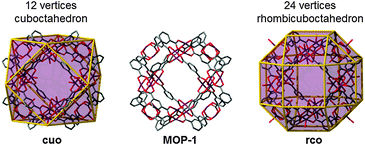
Fascinatingly, there exist only nine polyhedra that are edge-transitive. This feature is of prime importance in crystal chemistry as their augmented (truncated) polyhedron can be ideally employed as a polyhedron-blueprint to target the associated MOP and their subsequent assembly into related MOFs. Fig. 1 shows the edge-transitive polyhedra along with their derived truncated polyhedra. A closer look at these edge-transitive polyhedra reveals that seven out of nine are constructed exclusively from 3-c nodes, 4-c nodes or a combination of 3-c and 4-c nodes (i.e., tet, cub, oct, cuo, rdo, dod, and ido). Markedly, the three edge-transitive polyhedra (i.e., oct, cuo, ido) based on 4-c nodes have a similar corresponding square vertex figure, and are ideal targets in crystal chemistry for the construction of MOPs. That is, there are only three ways to link squares with one kind of edge into a polyhedron. It is to be mentioned that a vertex figure in a given polyhedron defines the points at which the MBBs are joined together to form the associated MOP (Fig. 2).
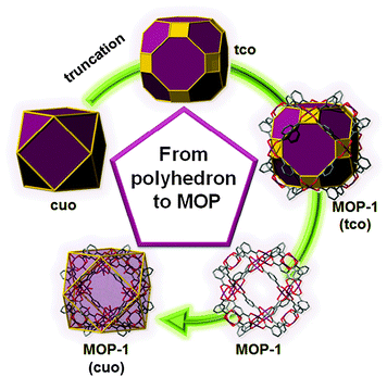 | ||
| Fig. 2 Schematic showing the relation between the edge-transitive cuboctahedron and the copper-isophthalate MOP-1. | ||
The requisite inorganic 4-connected square MBBs are readily accessible via metal–ligand directed coordination chemistry. This is exemplified by the dinuclear square paddlewheel cluster occurring with various metals (Ru, Cu, Rh, No, Fe, Ni, Co, Re, Cr, Zn, Mn, W, Tc, Os, Bi, Rh/Bi, Pt, Al, Mg, In, Pd/Co, Pd/Mn, Pd/Zn).30 The paddlewheel-shaped MBB offers access to a plethora of structures,31 due to its relatively low connectivity (4-c or 6-c, typically); its combination with organic ligands has been extensively studied and some synthetic conditions are already well-established permitting access to the aforementioned MBB in situ, and its transposition into specific structural motifs.
2.1. Metal–organic polyhedra (MOPs)
![[thin space (1/6-em)]](https://www.rsc.org/images/entities/char_2009.gif) :
:![[thin space (1/6-em)]](https://www.rsc.org/images/entities/char_2009.gif) 2 M to L ratio. Interestingly, the M24L48 MOP obtained can be regarded as a rhombicuboctahedron, which is not an edge-transitive polyhedron. The expected edge-transitive MOP for the assembly of squares with bent ligands having angles in the range of 134–149° should have been an M30L60ido-MOP (with an ideal bent angle of 144°). This finding reveals the capability of isolating additional closely-related MOPs that could each offer potential for the rational design and construction of MOFs. Along the same line, since the first use of the name metal–organic polyhedron and the abbreviation of MOP, with the report of Cu-paddlewheel-based MOP-1,34,35 exploration of similar systems based on paddlewheels (Mo, Cu, etc.) linked through dicarboxylate-based ligands has led to the isolation of several MOPs (M2L4, M3L6, M6L12, M12L24) by varying the bent angles of the ligands from 0 to 120°.36–38
2 M to L ratio. Interestingly, the M24L48 MOP obtained can be regarded as a rhombicuboctahedron, which is not an edge-transitive polyhedron. The expected edge-transitive MOP for the assembly of squares with bent ligands having angles in the range of 134–149° should have been an M30L60ido-MOP (with an ideal bent angle of 144°). This finding reveals the capability of isolating additional closely-related MOPs that could each offer potential for the rational design and construction of MOFs. Along the same line, since the first use of the name metal–organic polyhedron and the abbreviation of MOP, with the report of Cu-paddlewheel-based MOP-1,34,35 exploration of similar systems based on paddlewheels (Mo, Cu, etc.) linked through dicarboxylate-based ligands has led to the isolation of several MOPs (M2L4, M3L6, M6L12, M12L24) by varying the bent angles of the ligands from 0 to 120°.36–38
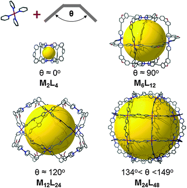 | ||
| Fig. 3 Illustration of the strong influence of the bent angle of the ligand on the geometry of the resulting MOP. | ||
Furthermore, the possibility for synthesis of expanded MOPs has been demonstrated, either by extending the lengths of a ligand,39 or by the incorporation of ligands with various angles in the same polyhedron.40 This mixed-ligand strategy allows the discovery of more complex and finely-tailored MOPs that can surely be used in fine for the formation of very complex extended structures.10 For a more complete overview of the fascinating MOP structures, the reader is invited to read the excellent and well-documented reviews of Stang et al.41,42 and Zaworotko et al.43
2.2. MOPs for MOF design
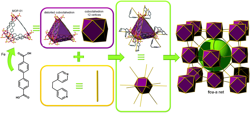
![[4 with combining macron]](https://www.rsc.org/images/entities/char_0034_0304.gif) 3m symmetry; contractions of only 0.4 Å between adjacent tetrahedra in IRMOP-51 are required for connection to occur in MOF-500.
3m symmetry; contractions of only 0.4 Å between adjacent tetrahedra in IRMOP-51 are required for connection to occur in MOF-500.
While considering the structure of MOF-500 as bridging of MOP-51 (distorted cuboctahedron, 12 points of extension) through 2-c ligands, the structure can be defined as having fcu topology. However this net can also be regarded as crs topology with a [Fe3O(SO4)3(–O2CR)3(py)3] unit as a uninodal 6-c MBB, where the MBBs form two different kinds of corner-shared tetrahedral MOPs in a staggered fashion (Fig. 6). In the network, the 6-c [Fe3O(SO4)3(–O2CR)3(py)3] MBB of C3v (3m) point symmetry is interconnected via three 2-c BPDC ligands (where, H2BPDC = 4,4′-biphenyldicarboxylic acid) and three 2-c BPE ligands. Four MBBs are interconnected via six BPDC ligands to form a tetrahedral MOP and other four 6-c MBBs are similarly interconnected via six BPE ligands to another tetrahedral MOP. These two different kinds of tetrahedral MOPs are corner-shared in a staggered fashion and the topology of the network is a dia-b-e (an edge net of dia-b (binary dia)). It is worth mentioning that dia (diamond) is the default (most commonly occurring) net for the assembly of tetrahedra.
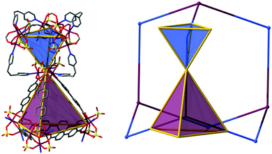 | ||
| Fig. 6 MOF-500 can be regarded as the assembly of two distinct tetrahedral cages. In this case, the resulting topology is dia (or dia-b-e). | ||
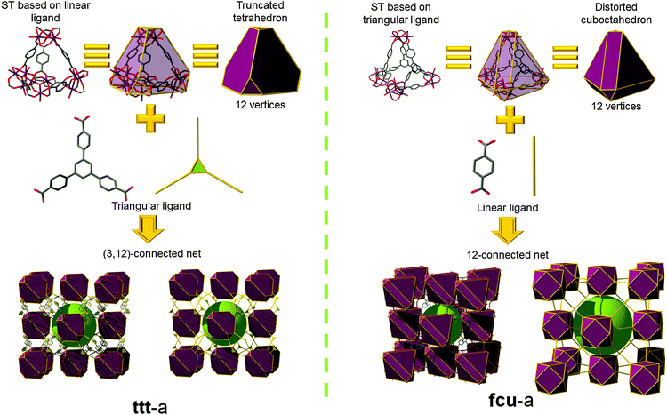
Férey et al. reported a key contribution based on corner-shared tetrahedral SBBs, resulting in the discovery of mesoporous MOFs having a zeolite topology; at the time of their discovery these MOFs had some of the highest specific surface areas reported. These unique MOFs, namely MIL-100 and MIL-101, are based on the self-assembly of similar metal–organic supertetrahedra (STs).46–48 The arrangement of organic linkers, respectively 1,3,5-benzenetricarboxylate (1,3,5-BTC; trimesate) and 1,4-benzenedicarboxylate (1,4-BDC; p-BDC, terephthalate), and inorganic trimers leads to the formation of a large ST. The ST is built in such a way that the four vertices of the ST are occupied by trimers while the organic linkers are located at the four faces or six edges of the ST. The connection of STs is established through vertices to ensure a 3-periodic network of corner-shared tetrahedral SBBs. When considering the assembly of these STs in MIL-100 and MIL-101, the MOFs exhibit the same topology (mtn) related to the MTN zeolite, but a precise analysis of points of extension reveals an important difference. Despite the fact that both have 12 points of extension, an ST built up from inorganic trimers (M = Cr, Fe, Al, etc.) and the 2-c 1,4-BDC (MIL-101) possesses vertices which match those from a truncated tetrahedron, while an ST built from the same types of inorganic trimers but with the 3-c 1,3,5-BTC ligand (MIL-100) can be regarded as a distorted cuboctahedron. This difference is of prime importance as it exemplifies the possibility of using STs as SBBs for synthesizing structurally-related MOFs.
Indeed, Serre and co-workers have recently reported a novel mesoporous MOF, MIL-143, synthesized using a mixed-ligand strategy. MIL-143 is built up from two kinds of STs (the one from MIL-101, and a benzene-tribenzoate (BTB) expansion of the ST from MIL-100).49 From a topological point of view, this structure can be interpreted in several different ways (Fig. 7). The first one is to consider the truncated tetrahedron STs (composed of six linear 1,4-BDC ligands) as the SBBs; which, when connected through the triangular BTB ligands leads to the binodal (3,12)-c network with ttt topology. Alternatively, if the expanded STs (with BTB on the faces) are considered as the SBBs, they are then linked through the linear 1,4-BDC ligands, which results in the interpretation of the structure as the well-known fcu topology. Both fcu and ttt are edge-transitive nets, therefore the obtained structures are those with the higher probability to form. Similarly to MOF-500, these MOPs can be considered as tetrahedra, which are corner-shared in a staggered fashion, and the topology of the network is dia-b-e. This is actually the only way for linking corner-shared staggered tetrahedra with a 180° angle.
Thus, the use of tetrahedral SBBs can provide access to diamond topologies, diamond-related topologies, and the zeolitic mtn topology. In fact, Férey and coworkers have shown the potential to construct other MOFs related to additional zeolitic topologies through molecular modelling of hypo-MIL-1 and hypo-MIL-2.50
Vertex-linked MOCs. Eddaoudi et al. reported the utilization of these MOCs as SBBs, highlighting the ability to cross-link them into 3-periodic MOF structures with zeolite-like topologies, i.e., zeolite-like metal–organic-frameworks (ZMOFs). The ZMOFs could be constructed by linking these MOCs via linear links, thus giving rise to MOFs having lta26 or aco52 (also known as pcb) topologies (Fig. 8). Alternatively, linking these MOCs through 4-c nodes should result in ZMOFs having ast (Fig. 8)26 or asv topologies. The aforementioned zeolite nets (aco, ast, asv, and lta) are especially interesting to reticular chemistry as their nets correspond to the augmentation of the edge-transitive nets bcu, flu, scu, and reo, respectively, where the d4Rs serve as the cube-like vertex figures.53 Specifically, bcu and reo are both semi-regular 8-c nets, and scu and flu are edge-transitive (4,8)-c nets.26,52
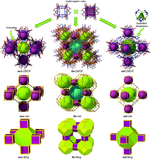 | ||
| Fig. 8 MOCs can be externally functionalized to serve as SBBs for the assembly of MOFs with zeolitic topologies. | ||
Different research groups have contributed to the development of MOC-based materials, using the vertex-linked strategy showing exclusively pcu or aco topologies.54,55 Feng et al. also reported the reaction of Zn(II), imidazole (HIm), and 5-methylbenzimidazole (HMBIm) in the presence of (±)-2-amino-1-butanol and benzene, which yielded the zeolitic network, TIF-3, with aco topology based on the [Zn8(Im)6(MBIm)6]4− cluster as a cubic MOP.55
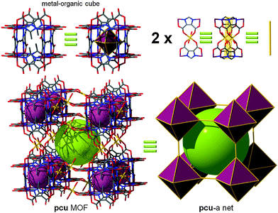
Edge-linked MOCs. Xu et al. reported ([Li11(Ni8L12)(H2O)12]Li9(H2O)20)n in which [Ni8L12]20− MOPs are bridged via the four oxygen atoms from two edge-ligands of two adjacent cubic MOPs. Of the twelve edges of the cubic MOP, only six edges are alternately linked to the six adjacent cubic MOPs. This MOP can be considered as an octahedral 6-c node, and hence, the network can be viewed as having a distorted pcu network topology (Fig. 9).54 Chen et al. reported a MOF based on a doubly edge-center-linked cubic MOP exhibiting a pcu topology. Indeed, the arrangement of doubly-linked cubic MOPs, considered as a 6-c octahedral node, displays primitive cubic packing (Fig. 10).56
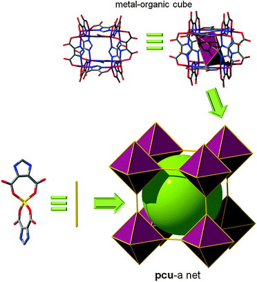 | ||
| Fig. 9 Cross-linkage of Ni-based MOCs by half of their vertices with Li leads to a MOF with underlying pcu topology, where the MOC is 6-c, forming an octahedral SBB. | ||
In 2009, Zhou et al. reported a related MOP built up from 9H-carbazole-3,6-dicarboxylate (CDC). It was anticipated that the N–H functional groups of the ligands would form hydrogen bonds with appropriate solvent molecules, improving the solubility of the ensuing MOP. The Cu2(–O2CR)4 paddlewheel clusters occupy the six corners of an octahedron, while labile terminal ligands cap the two axial positions of paddlewheel units. The ligand substitution of the outer labile axial ligands with bridging ditopic organic linkers, here 4,4′-bipyridine, leads to the formation of an extended structure from this MOP with pcu topology (Fig. 11).38 The resulting MOF can alternatively be described as a 5-c net of cab topology. Specifically, the net corresponds to cab-c (twofold catenated cab) topology and contains the octahedral MOP based on CDC as a 2-c bent edge and the paddlewheel cluster [Cu2(–O2CR)4] as a 4-c square planar MBB. The octahedral MOP is further interconnected via 4,4′-bipyridine linkers to the network of a cab (pcu-a) topology based on the octahedral MOP as a 6-c octahedral SBB.
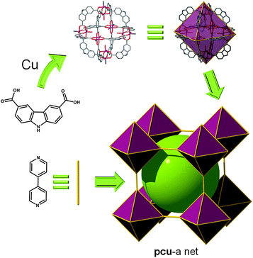 | ||
| Fig. 11 Linear bridging of the CDC-based MOP through the apical position of the six paddlewheels leads to an SBB-based MOF with pcu topology. | ||
Furthermore, by using the versatility of the above described CDC-based SBB, but now bridging them through functionalization of the bent position of the ligand, this octahedral SBB can also be regarded as a 12-c cuboctahedron (the same principle as depicted in Fig. 4). This SBB is amenable to the formation of a MOF with fcu topology (Fig. 12).22
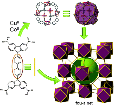 | ||
| Fig. 12 Linear bridging of the CDC-based MOP by the bent position of the twelve ligands (i.e., using a tetracarboxylate ligand) leads to an SBB-based MOF with fcu topology. | ||
In fact, the first examples of SBB-based fcu-MOFs were published by Eddaoudi, Zaworotko, et al. in 2008.23 The topology of the resultant MOFs (e.g., [Ni2(ABTC)(H2O)3] (H4ABTC = 3,5-dicarboxyl-(3′,5′-dicarboxylazophenyl)benzene)) can be rationalized in two different but equally valid ways. The octahedral building unit can be interpreted as a 12-c SBB, in which the squares are assembled by connecting the centroids of the benzene rings. A decorated cuboctahedron SBB of formula M6L12 is thereby revealed. The SBBs are connected through the ligand to generate the observed face-centered cubic (fcu) network. On the other hand, if one selects to choose the carbons of the carboxylates as a point of extension, then the framework can be interpreted as a MOF assembled from two distinct 4-c nodes: a square MBB and a rectangular ligand. The M6L12 moieties would be regarded as an assembly of squares, rectangles, and hexagons, generating cages resembling those in the zeolite structure sodalite. In these MOFs, the twelve-connected SBB is not made from regular paddlewheels, as the 120° angle from the terminal isophthalate moieties would not allow the formation of a cuboctahedron. The SBB is then made from “pseudo-paddlewheels” constructed from two crystallographically independent metals, which adjusts for the necessary angle.23
This MOF can alternatively be described as an nbo-MOF, or as a (3,4)-c net of a tfb topology when the 4-c ligand is regarded as two 3-c nodes.58 Twelve 1,3-benzenedicarboxylate (1,3-BDC; m-BDC; isophthalate) groups of the tetracarboxylate ligands and six M(II) ions from an octahedral MOP as 2-c edges and 4-c corners, respectively, in the network. The MOP as an SBB was further interconnected to the twelve neighboring/surrounding MOPs in cubic close packing arrangement through the twelve edge-centers of the octahedral MOP in the (3,4)-c network of tfb topology.
pcu topology. To the best of our knowledge, only the first way of decoration described previously can be applied to allow the crystallization of MOFs with pcu topology. Moreover, the functionalization of the 5-position of the bent ligand involves, depending on its length and flexibility, three kinds of linkage of the cuboctahedra between: (i) the same two square faces, called A–A, (ii) the same square nodes, called B–B, or (iii) between one square face and one square node, called A–B (Fig. 13).
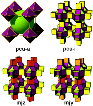 | ||
| Fig. 13 Different possible ways for the quadruple cross-linking of 24-coordinated rhombicuboctahedron affording underlying pcu topology. | ||
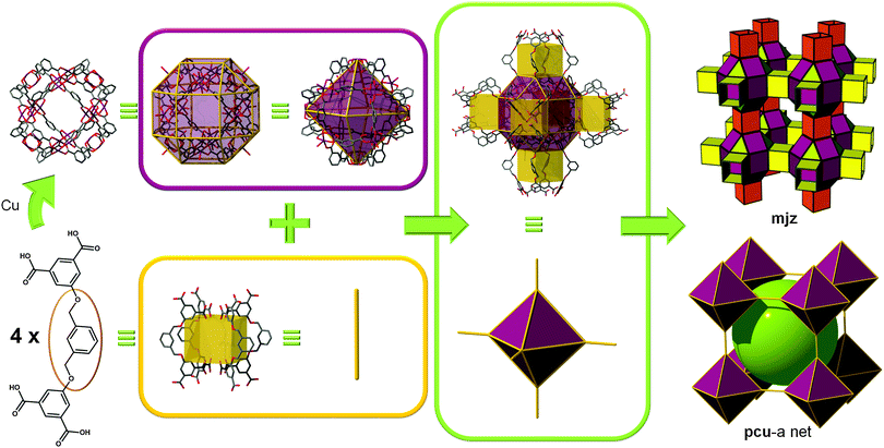
In 2007, Zaworotko et al. reported a MOF built from such an SBB. A tetracarboxylate ligand was designed with the aim of employing/linking MOPs via the 5-position of 1,3-benzenedicarboxylate moieties. The authors noted that one cuboctahedral MOP is quadruply edge-center interlinked to the six neighboring MOPs in a primitive cubic arrangement via the 24 edge-centers of the MOP (Fig. 14). In other words, two different kinds of quadruple linkages, two AA-type and four BB-type are observed leading to a pcu underlying topology.60,61 Alternatively, the structure can be deconstructed in a different way to afford mjz topology. In 2009, Lah et al. reported an isoreticular analogue using 1,3-bis(3,5-dicarboxylphenylethynyl)benzene as the ligand.62
Zhou et al. reported another MOF, PCN-12,63 illustrating a quadruply edge-center-linked cuboctahedral MOP. However, although the net has the same pcu underlying topology, the types of the quadruple linkages differ from those described in the previously cited MOFs. While two different kinds of quadruple edge-center-linkages, AA-type and BB-type, are observed in the former, only one different kind of quadruple edge-center-linkage, AB-type, between the square face of the cuboctahedral MOP and the square node of the cuboctahedral MOP is observed in the current MOF.
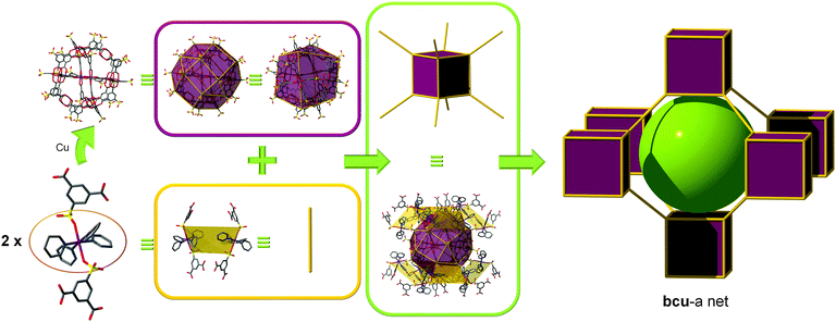
bcu topology. To the best of our knowledge, only one SBB-based MOF exhibiting a bcu topology is reported. Zaworotko et al. isolated the conditions to synthesize a sulfonated anionic MOP, formulated as ([Cu2(5-SO3-1,3-BDC)2(4-methoxypyridine)0.50(MeOH)x(H2O)1.50−x]12)24−, by modular self-assembly in MeOH under ambient conditions of 5-SO3-1,3-BDC moieties, Cu(II) cations, and coordinated base (4-methoxypyridine) molecules.64 Importantly, all 24 sulfonate moieties are exposed at the exterior of the nanoball, which is pseudooctahedral in symmetry. They are therefore predisposed for coordination to Cu(II), and, in the presence of excess copper(II) nitrate, 16 sulfonate moieties bind to 16 [Cu(methoxypyridine)4]2+ cations, thus facilitating cross-linking via axial coordination to a second sulfonate moiety in the adjacent nanoball. The cuboctahedral MOPs are doubly interconnected to the edge-centers of the eight adjacent MOPs via the coordination of the sulfonate group at an edge-center to a 2-c [Cu(methoxypyridine)4] node. Because of the symmetry of the MOP, the crystal packing is necessarily bcc giving rise to a bcu underlying topology (Fig. 15). This MOF can alternatively be described as having a gjm topology.
fcu topology. The deliberate construction of MOFs displaying a 12-c fcu topology using this type of cuboctahedron MOP is achievable only by functionalization of the axial position of the paddlewheel with a linear ligand due to the symmetry of the MOP. Of course, the modularity of the MOP (e.g., different metals, the large choice of ditopic bent ligands, functionalized or unfunctionalized) leads to a high number of possible combinations and hence a large number of potential MOFs.
To illustrate this strategy, we describe here the first example, [Zn4(1,3-BDC)4(DABCO)(OH2)2] (DABCO = 1,4-diazabicyclo[2.2.2]octane), reported by Chun (Fig. 16).65 The twelve corners of the cuboctahedral MOPs represented by the Zn(II) paddlewheel are then connected to the other neighboring cuboctahedral MOPs via the ditopic DABCO. This structure can alternatively be described by considering the Zn(II) paddlewheel as a 5-c MBB giving rise to a ubt topology.
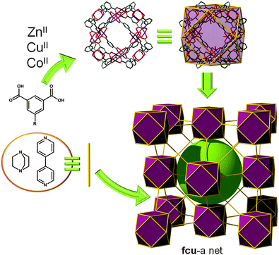 | ||
| Fig. 16 Linear bridging (using DABCO or 4,4-bipyridine) of MOP-1 analogues by the apical position of the twelve paddlewheels leads to an SBB-based MOF with fcu topology. | ||
To exemplify the versatility of this SBB-based fcu platform, other examples have been reported, substituting Zn with Co (i.e., metal substitution),66 replacing the m-BDC by 2,7-naphthalenedicarboxylate (i.e., enlargement of the 12-c SBB),66 or using the amino-functionalized MOP-14 (i.e., decoration of the 12-c SBB)67 with bipyridine (i.e., expanding the available space between the SBBs).67
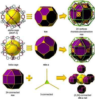
rht topology. As depicted in Fig. 4, the cuboctahedral MOP-1 can also be regarded as a 24-connected rhombicuboctahedron SBB, where the MOP can be externally functionalized at the 5-position of the 1,3-BDC ligand, and thus afford the establishment and peripheral exposure of 24 points of extension for potentially linking the MOPs into a 3-periodic MOF. Although MOP-1 was first reported in 2001, its potential use as an SBB was not fully recognized until 2007 by Eddaoudi et al. This foreseen deferred recognition is mainly due to the late enumeration of the singular (3,24)-c edge-transitive net, rht net, with associated vertex figures as a rhombicuboctahedron for the 24-connected vertex and a triangle for the 3-connected vertex, overlooked in the original list of enumerated 3-periodic edge-transitive nets and then recognized and appended to the list by O'Keeffe et al. mid-2007.68 The disclosure of the rht net, the only (3,24)-c edge-transitive net, combined with the fact that edge-transitive nets are suitable targets in crystal chemistry immediately prompted Eddaoudi's group to explore various avenues to transpose and reveal the rht topology in MOF chemistry. Nevertheless, MBBs with connectivity of 24 are presently too intricate to be systematically obtained by means of simple organic ligands or polynuclear clusters. The scarcity of 24-connected MBBs, in particular, and the difficulty in isolating reaction conditions that permit the formation of highly-connected MBBs (i.e., ≥12) have triggered the naissance of the idea and founding of the SBB approach as a means to access highly-connected (i.e., ≥8) building blocks and subsequently use them for the construction of highly-connected MOFs.
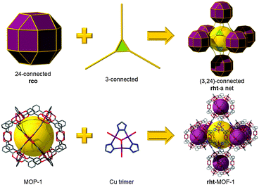
As soon as this edge-transitive rht net was disclosed as a plausible net for the assembly of 3- and 24-connected building units (not as a chemical structure), Eddaoudi et al. pioneered and employed the SBB approach for the deliberate construction of MOFs with rht topology. Introduction of rht-MOFs was based on the employment of the functionalized cuboctahedral MOP-1 as a 24-connected rhombicuboctahedron SBB, where the MOP is externally functionalized at the 5-position of the 1,3-BDC, and a Cu-trimer as the cross-linking 3-connected MBB (Fig. 17).13 Concurrently, Lah et al. employed a hexacarboxylate (what we term “trefoil”) ligand that afforded the construction of the first disclosed rht-MOF based on covalently linked 3-c nodes.69
Comprehensively, the rht net is a singular net for the assembly of 24-c vertices (rhombicuboctahedral, rco) and 3-c vertices (triangular). Indeed, trigonal or 3-c organic ligands can be readily synthesized, allowing for a high degree of tunability or choice in the trigonal MBBs (Fig. 19). In contrast, 24-c MBBs are relatively rare, and organic molecules with high connectivity typically lack sufficient solubility required for MOF synthesis. Therefore, the SBB approach is ideal, utilizing externally (based on the bent position of the ligand) functionalized cuboctahedral MOPs as rhombicuboctahedral SBBs and thus allowing access to the requisite high-connected vertices (i.e., rco) necessary for the construction rht-MOFs.
The SBB strategy was exemplified in the original report of the first rht-MOF.13 By including tetrazole functionality at the 5-position of the isophthalic acid (1,3-BDC) precursor, a rhombicuboctahedron having 24 external tetrazole groups (a 24-c vertex with rhombicuboctahedral geometry) could be formed in situ. Under appropriate conditions, the external tetrazoles form trimers having triangular geometry, thus allowing the linking of the MOPs, resulting in the formation of rht-MOF-1.
It is worth mentioning, from a pure topological analysis perspective, that the rht-MOF-1 can be deconstructed into basic building blocks, namely 3-c and 4-c MBBs. Accordingly, as stated in the original paper, rht-MOF-1 can be alternatively described as a (3,3,4)-c net based on its basic building blocks (recently dubbed ntt). Nevertheless, such a description, based on employment of the information solely built in the 3-c and 4-c MBBs, does not provide the requisite coded information for the directed formation of rht-MOFs, i.e., simple combination of three distinct basic 3-c and 4-c MBBs is not sufficient for the design of rht-MOFs. Whereas, the SBB approach permits the use of the functionalized cuboctahedral MOP-1 as a 24-connected rhombicuboctahedron SBB, the rht-coded building units (rht-cBUs), where precise embedded geometrical information codes uniquely and matchlessly for the rht net and the deliberate construction of rht-MOFs.
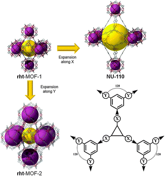
It has recently been demonstrated that this rht platform can be tuned via five basic pathways (Fig. 18):12
(1) Expansion of the SBB
(2) Modification of the distance between the SBB and the trigonal MBB
(3) Substitution/modification of the triangular MBB
(4) Functionalization of the ligand
(5) Use of different metals (Cu, Zn, Co, etc.).
Thus, this patented strategy24 allows the easy expansion and decoration of the SBBs on demand and also allows us to “choose” a cationic or neutral MOF through use of the tetrazole-based trigonal MBB or use of the purely organic MBB (trefoil ligand), respectively.12
The singular nature of the rht net (i.e., the sole net for the combination of 3-c and 24-c nodes) offers a high/unprecedented degree of predictability toward its successful transposition in MOF chemistry. Of additional importance, the rht-MOF platform offers independent expansion parameters (without concern for interpenetration; i.e., not self-dual), which has led to one of the highest levels of tunability achieved in MOFs. This feature is clearly reflected in the large number of rht-MOF structures reported in the open literature; since the first public report in January 2008,13 almost fifty derivative rht-MOFs have been reported (Fig. 19).12,13,20,21,69–85 The rht-MOF platform allows access to MOFs with unprecedented surface areas; namely NU-110, based on an expanded trefoil ligand, has exhibited one of the highest BET surface areas (SBET = 7140 m2 g−1).86,87
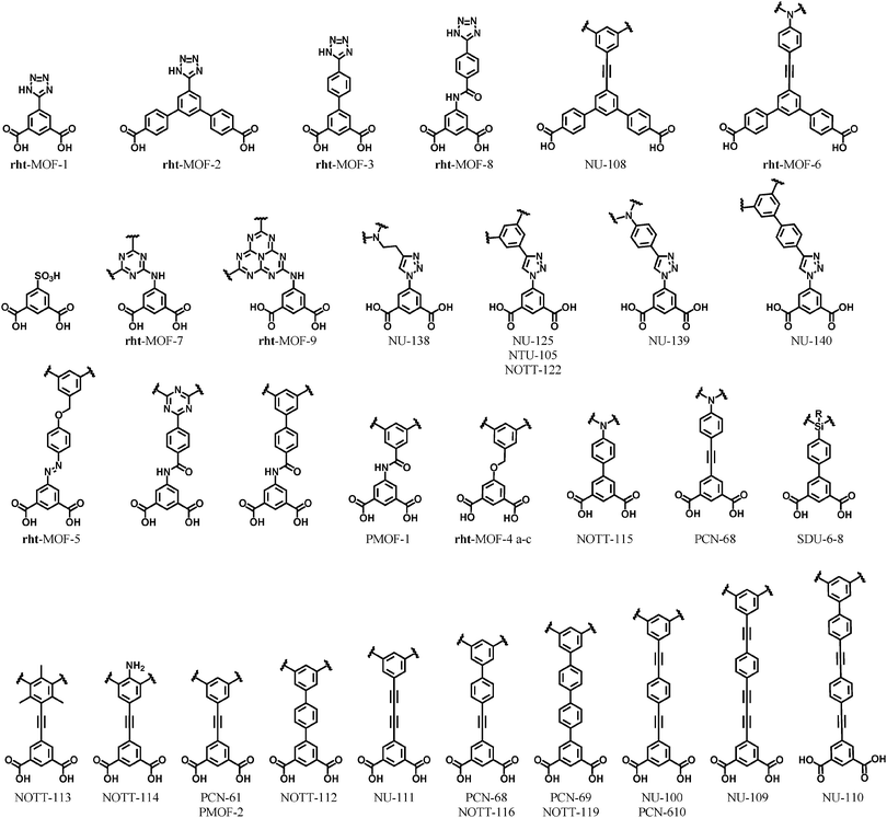 | ||
| Fig. 19 Tetrazole and trefoil ligands utilized for rht-MOF synthesis. Given name(s) for the related MOF are listed, when applicable. | ||
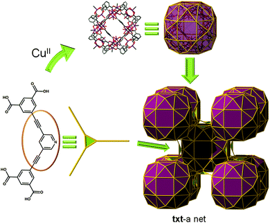
txt topology. Up to now, the linkage between cuboctahedron MOPs can be realized in two separate ways: (i) Vertex-to-vertex, where the MOP is regarded as a 12-c SBB, or (ii) edge-to-edge fashion, where the MOP is acting as a 24-c SBB. A third possible configuration, i.e., vertex-to-edge connection, is evident, which results in the cuboctahedron MOP being viewed as a 36-c SBB.
Indeed, Zhang et al. reported a txt-MOF with txt topology based on the (3,36)-c net. A 1,3-bis(3,5-dicarboxylphenylethynyl)pyridine ligand was employed as a 3-c node (Fig. 20).88 The cuboctahedral MOP is connected via the 24 edge-centers and the 12 corners (apical position of the copper paddlewheel cluster) of the MOP to six adjacent MOPs in primitive cubic arrangement via quadruple edge-center linkages. An amide-functionalized analogue (PCN-124) was recently found to show improved CO2 uptake at 273 K.89 The network is alternatively described as a (3,5)-c net with a pzh topology, where the ligand was considered as a (3,3)-c node consisting of two different kinds of 3-c nodes and the [Cu2(–O2CR)4(pyridyl)] cluster as a 5-c node.
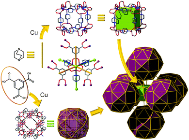
Other topologies. Lian et al. also reported a 3-periodic network, [Cu24(–NRx)4(1,3,5-BTC)12(DABCO)9(H2O)6]·8(NO3),90 containing a cuboctahedral MOP as a 36-c SBB (Fig. 21). The network contains the characteristics of the nets of fcu and of ubt simultaneously. A 1,3-BDC unit of the 1,3,5-BTC ligand acts as an edge and the [Cu2(–O2CR)4] paddlewheel cluster as a 4-c MBB, forming cuboctahedral MOP as an SBB. The 4-c [Cu2(–O2CR)4] paddlewheel clusters of the cuboctahedral MOP are interconnected to twelve other cuboctahedral MOPs in a cubic close packing arrangement via DABCO linkers, as in the network of the fcu topology, and the three adjacent cuboctahedral MOPs in the network are further interconnected via a 3-c [Cu3(–NRx)(–O2CR)3] cluster, as in the network of the rht topology. In addition, the eight [Cu3(–NRx)(–O2CR)3] clusters at the corners of a cube are further interlinked via DABCO linkers to a cubic cage at the octahedral cavity of the cubic close packing arrangement of the cuboctahedral MOPs leading to a (3,5,6)-c net of ott topology (Fig. 21).
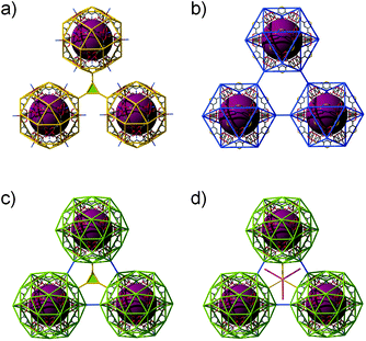
Comparison of ntt, ubt, nut, and ott topologies. All the nets of ntt, ubt, nut, and ott topologies are based on the same cuboctahedra, as an SBB, in cubic close packing arrangement (Fig. 22). In the (3,4)-c net of ntt topology, three cuboctahedra in close contact are interconnected via 3-c node through the edge-centers of the cuboctahedron (Fig. 22a). Whereas the three cuboctahedra in the 5-c net of ubt topology are interconnected via 2-c nodes through the corners of the cuboctahedron (Fig. 22b), in the (3,5)-c net of nut topology, the three cuboctahedra are interconnected via both 3-c node through the edge-centers of the cuboctahedron and 2-c node through the corners of the cuboctahedron (Fig. 22c). The networks with (3,5)-c nut topology are yet to be found synthetically. In the (3,5,6)-c net of an ott topology, in addition to the aforementioned linkages between the cuboctahedra in the net of the nut topology, the eight 3-c nodes, in a primitive cubic arrangement at the octahedral cavity of the cubic close packing arrangement of the cuboctahedra, are further interconnected via 2-c node (Fig. 22d).
pcu topology. Lah et al.91 reported the use of a 3-c organic node and a 4-c node leading to a (3,4)-c rhombic dodecahedral MOP. When the 4-c node of the MOP is further linked via an additional 2-c linker, the network based on a corner-linked rhombic dodecahedral MOP as an SBB could be achieved (Fig. 23). In this case, the rhombic dodecahedral MOP is considered as a 6-c SBB (octahedron) giving rise to a net of pcu underlying topology.
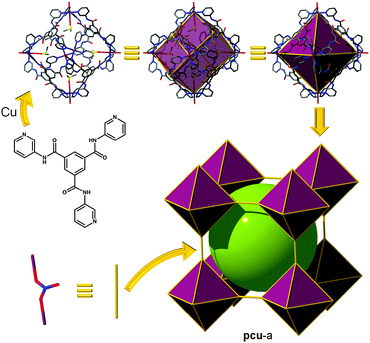 | ||
| Fig. 23 Linking rhombic dodecahedral MOPs by nitrate anions leads to an SBB-based MOF with pcu topology. | ||
Zhang et al.92 reported a rhombic dodecahedral (rdo) based SBB built using six [Zn2(–O2CR)4] clusters as 4-c MBBs, eight [Zn2(–O2CR)3] (or Zn(–O2CR)3) clusters as 3-c MBBs and the 1,3-BDC groups as the 24 edges. Each of the rhombic dodecahedral MOPs are quadruply interconnected between two square nodes of six neighboring MOPs in a primitive cubic packing arrangement giving rise to a pcu underlying topology. However, the rhombic dodecahedral MOP can alternatively be regarded a (3,4)-c net having zjz topology (Fig. 24).
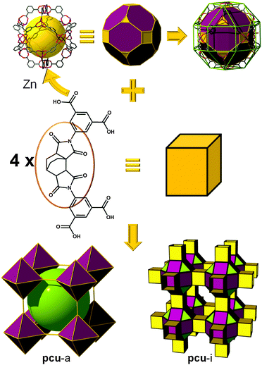 | ||
| Fig. 24 Quadruple crosslinking of rdo SBB (points of extension defining a rhombicuboctahedron) leads to an SBB-based MOF with pcu topology. | ||
rht topology. Recently, Sun et al. reported a very interesting zinc hexacarboxylate, containing both 3-c and 4-c paddlewheels.93 As in the previous example, the structure contains the rhombic dodecahedral (rdo) cage built from six 4-c paddlewheels and eight 3-c paddlewheels, bridged by 24 isophthalate moieties from a trefoil-like ligand. These 24 isophthalates are cross-linked through the central ring of the ligand in a similar fashion as the rht-MOFs described earlier in this review. This arrangement leads to a “beta” version of the ubiquitous (3,24)-c rht-MOFs (Fig. 25). The structure of this beta-rht-MOF can be alternatively described as a (3,3,4)-c net with tfe topology.
Interestingly, Yuan et al. simultaneously reported a zinc-trimesate, where the trigonal MBB is now substituted by another 3-c paddlewheel.94 Of course, there is no doubt this type of structure (beta-rht-MOFs) can be expanded by increasing the size of the branches between the 3-c central core (organic or 3-c paddlewheel) and the rdo cage, similar to what Eddaoudi et al. reported for the classical “alpha” rht-MOFs.12 Interestingly, the occurrence of the first beta-rht-MOF can be retroactively traced back to 2001 for a (3,3,4)-c structure reported by Zaworotko et al.95 It is not surprising that the beta-rht-MOF was not recognized back then, as the SBB approach to describe and construct MOFs, a more elaborate tool permitting to recognize net-cBUs, was not introduced until years later in 2007.13,23,24
gea topology. Finally, one of the latest additions to those highly-connected nets that are amenable to the SBB approach has been introduced recently by the Eddaoudi group, starting from the discovery of a novel (3,18)-c net, now in the RCSR and referred to as gea (Fig. 26).10 The initial MOF, gea-MOF-1, revealed the discovery of a nonanuclear rare earth cluster acting as an 18-c MBB linked by triangular tricarboxylate ligands. Immediately, upon the discovery of this new MOF system, Eddaoudi's group recognized the potential of this highly-connected net to be employed as a blueprint for the practice of the SBB approach. The requisite MOP (M9L18), containing the coded information suitable to transpose the observed connectivity of the inorganic cluster in the parent gea-MOF-1, has been previously reported.40 The aforementioned MOP results from the assembly of two types of bent ligands (6 × 90° and 12 × 120° angles) with copper paddlewheels. After careful geometrical analysis, a trefoil-like hexacarboxylate ligand, similar to those utilized for rht-MOFs, was designed to include one of the predisposed dicarboxylate moieties at a 90° angle, and the remaining two at 120°. As expected, the synthesized ligand, in combination with copper (paddlewheels), resulted in the formation of the MOP-based SBB in situ, which are also cross-linked to form the pre-targeted gea-MOF-2, the first SBB-based gea-MOF.
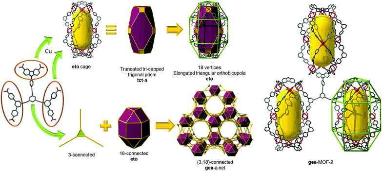 | ||
| Fig. 26 Schematic showing the design path followed to achieve the construction of gea-MOF-2, the first SBB-based gea-MOF. | ||
It is to be mentioned that the topology of gea-MOF-2 can be described as a (3,3,3,4,4)-c net having gwe topology. Nevertheless, such a penta-nodal net is far too complicated to allow for intuitive design of this material, a gwe-MOF, from simple combination of five distinct basic 3-c and 4-c MBBs.
2.3. MOPs for MOFs: Conclusion
As elucidated through all the aforementioned examples, the SBB approach relies on the use of a MOP as an elaborate building entity, programmed in order to contain the coded information essential to construct a targeted MOF with a given topology. The MOP encloses the requisite geometrical information with desired peripheral points of extension (connectivity) that match the net-cBUs' coding for a selected targeted net.The key perquisites to use the SBB approach for the design of a MOF are: (1) A blueprint net with minimal edge-transitivity, preferably singular, that is exclusive for the assembly of given building units, and not susceptible to self-interpenetration upon net expansion and/or decoration and (2) reaction conditions that permit us to consistently form the desired SBB.
3. Supermolecular building layers (SBLs)
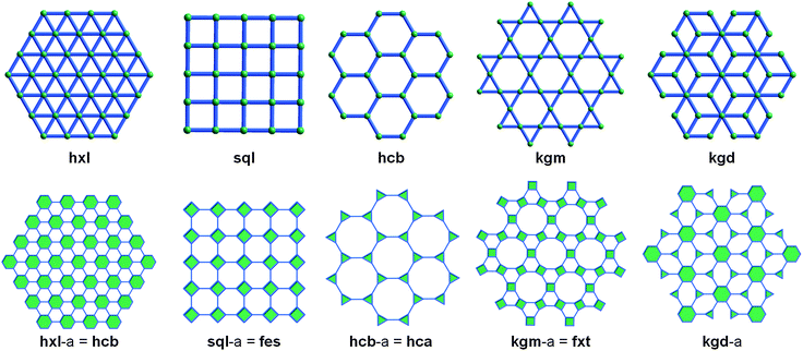
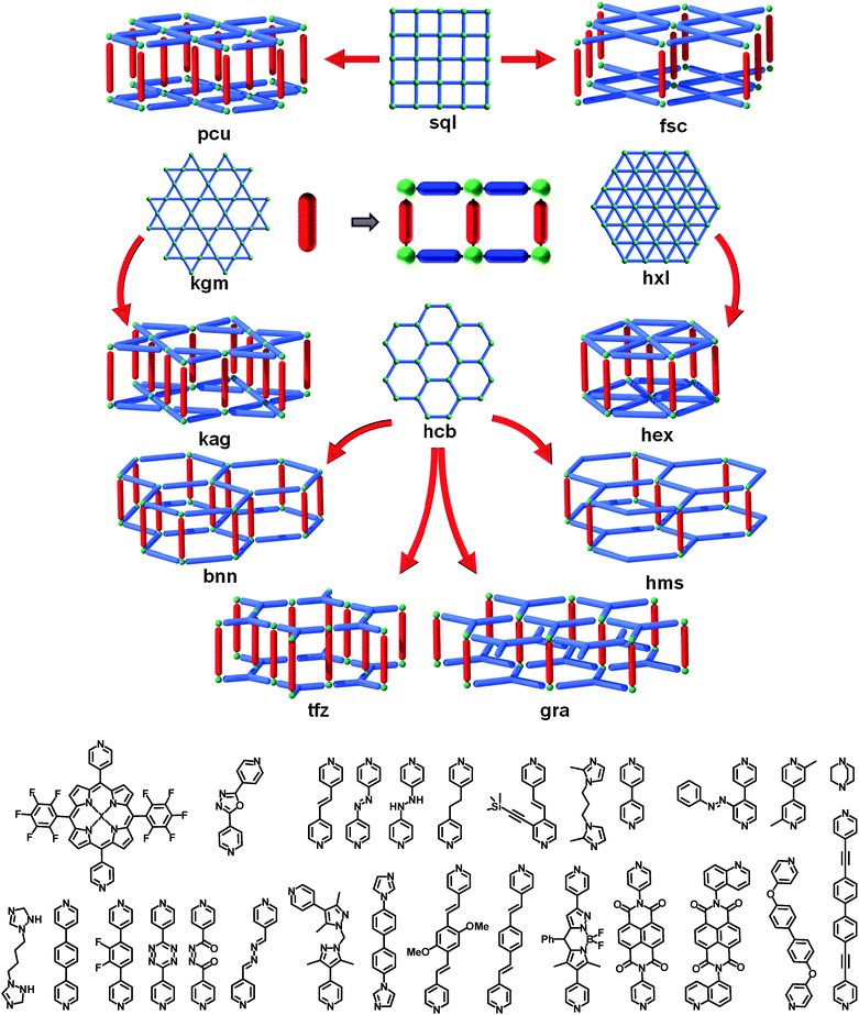
Many existing 3-periodic MOFs can be interpreted as consisting of inter-connected (e.g., pillared) layers (i.e., 2-periodic sheets). The underlying layers can be isolated through deconstruction of the crystal structure, and in fine, designed and constructed from judiciously selected metals and ligands. As mentioned earlier in this review, edge-transitive nets are ideal targets in crystal chemistry. To apply this to pillared-layer structures, it is important to recognize that there are only five edge-transitive 2-periodic nets that exist, sql (square lattice), kgm (Kagomé), hcb (honeycomb), kgd (Kagomé dual), and hex (hexagonal lattice). Targeting these nets and their corresponding pillared versions can facilitate rational design of MOFs (Fig. 27).Moreover, when regarded as augmented layers, it appears that, out of these five edge-transitive layered nets, two of them, sql and kgm, can be regarded as the assembly of squares (i.e., they are solely composed of 4-c vertices). These nets are thus suitable to target with metals able to form the ubiquitous (and aforementioned) 4-c paddlewheel (Cu, Ni, Fe, Zn, Co, etc.).31,96
Hundreds of examples of pillared MOFs can be found in the Cambridge Structural Database (CSD),97 most of them being quite simple pillaring, as will be described below. However, in 2011, Eddaoudi et al. introduced a powerful concept/strategy, namely supermolecular building layers (SBLs), that allowed the design and discovery of pillared MOFs with a much higher degree of complexity.98 Of course, this unique strategy is not restricted to complex pillaring, and is also applicable to simple pillaring.
The SBL approach leverages the possibility to utilize the readily targeted 2-periodic MOF layers (SBLs) as building blocks to construct, functional 3-periodic porous MOFs. This is accomplished by chemically cross-linking the layers through accessible bridging sites on the layers (e.g., open-metal site or functionalizable position of the organic linker). This design method requires judicious selection of organic ligands that will pillar the layers. As a result of the countless cross-linking combinations, myriad MOFs having specific underlying 3-periodic network topologies can be designed and synthesized utilizing the pre-targeted SBLs. An additional advantage of this approach is the fact that the overall framework and network topology will remain constant, based on the pillared layers, allowing practically endless expansion of the confined space (e.g., cavities, porosity). It can also be noted that, if the pores or windows of the layers remain unexpanded (i.e., expansion of the pillar only), any concern for interpenetration, a plague of many expanded MOFs, is precluded. The inherent modularity of this method allows for facile functionalization or introduction of additional functionalities (e.g., free carboxylic acid groups98) to target specific applications (e.g., MOF platforms for CO2 capture, gas separation, controlled drug release, etc.).99
3.1. Axial-to-axial pillaring
The first and, apparently, most obvious way for the pillaring of MOF layers takes advantage of neighboring accessible metal sites; this can be referred to as axial-to-axial (A–A) pillaring. Perhaps the most common, readily constructed, and well-known examples involve MOFs having sql or kgm topology and are based on the aforementioned square paddlewheel dimer MBBs [M2(–O2CR)4(A)2; M = metal, A = axial ligand] bridged by ditopic organic ligands [e.g., benzenedicarboxylates, such as terephthalate or isophthalate].31,96,100 In these examples, the axial sites of the square (4-c) paddlewheel orient outward toward the upper and lower surfaces of the MOF layer. In 2-periodic materials, these sites are typically occupied by terminal ligands (e.g., water, pyridine, or DMF) that do not play a role in the network topology. Thus, utilizing a linear, bifunctional or ditopic ligand (e.g., azolated ligands, such as DABCO101–128 or bipyridine113,126,129–141) allows coordination to neighboring open-metal/axial sites (i.e., now 6-c, octahedral) and resultant cross-linking of separate/independent layers (Fig. 28). Thus, the sql-MOFs could be employed as SBLs amenable to pillaring via cross-linking through linear organic linkers to construct the desired MOF platform having pcu topology, pcu-MOF, based on linear bridging of 6-c (octahedral) nodes. Surprisingly, the first and intended formation of such a MOF by Seki, Mori, et al. in 2001, has been barely cited,101 despite a large series of isoreticular mixed-ligand pcu-MOFs that have since been produced, derived from their pioneering approach.Indeed, there are many distinct examples of such pcu-MOFs, due to the exceptional tunability of this platform. It is possible to substitute the original Cu103,108,110,125,129,131,137,140 from the SBL with other metals, such as Zn,102,104–106,108,110–119,122–126,130,132,133,135,136,138,142–157 Ni,109,127,139 Co,107,120,121,134,139,141,158,159 Mn,160 Fe,128 Cu/Zn,125etc., but also to vary the length (1,4-BDC,105,107,109,110,113,118,121–126,128,132,135,142,143,145–149,160 2,6-NDC,103–111,113,119,120 4,4-BPDC,135etc.135) or functionality (–NH2,111,114,119,160 –NO2,106 –F,103,113,146 –Me,113,134 –Cl,116,119 –Br,116,119 –COOH,114,129,130,137 –OH,111,117 –naphthalene–,108,113,144 –anthracene–,112,115,138etc.102,104,136) of the dicarboxylate ligand, as well as the pillars (e.g., DABCO,102–128 bipyridine,113,126,129–141 benzene-bipyridine,146 functionalized bipyridines,143,152,154 di-triazole,148etc.,131,133,135,140,142,144–147,149–151,153,155–157,159,160Fig. 28).
In addition to the paddlewheel-based SBL, the SBLs can be constructed from a variety of metal clusters and/or single-metal ions and organic bridging ligands,161 and the pillar can be any other ditopic entity, such as organic dicarboxylates162 or inorganic (e.g., SiF6),163 resulting in limitless possibilities for novel 3-periodic MOFs.
Another type of sql layered material, mainly explored by Hupp et al.164–175 and Choe et al.,176–180 can be constructed from 4-c carboxylate ligands, such as porphyrin tetra-benzoates, leading, in most cases, to MOFs with a (4,6)-c fsc topology. They can be seen as variations of the above described pcu-MOFs, where half of the pillars are missing, offering therefore more potential accessible voids. Interestingly, the simultaneous pillaring of paddlewheels and porphyrins can sometimes occur, leading to MOFs with pcu topology, but also more complex nets that we will not describe here, as they are not reasonably targetable as part of the SBL design strategy.176–180 The first fsc-MOF was reported in 2007 by Feng et al., based on Cu6I6 and Cu8I8 MBBs bridged by DABCO, but again, would be difficult to employ in a pillaring strategy.181
Interestingly, the number of kag-MOFs, i.e., kgm layers pillared in the same A–A fashion is scarce. These MOFs would potentially offer more void space than their pcu analogues.109,123,126
Other two-dimensional layers are well-known in coordination chemistry182–184 and in 2003, another example of A–A pillaring was reported by Rosseinsky et al. based on Ni3BTC2 honeycomb layers, pillared by 4,4-bipyridine, leading to a (3,4)-c tfz-MOF.185 Interestingly, in this SBL, Ni plays the role of a 2-c node that bridges the 3-c BTC ligands; also, it is possible to “inverse” the roles and find in the literature a layer constructed of 3-c Zn paddlewheels bridged by triptycene–dicarboxylate.162 In this particular case, the ligands also act as pillars to form a 5-c net with bnn topology. These pillars are connected in a monodentate coordination fashion, and one can reasonably imagine replacing them by other types of ligands without affecting the formation of the SBL, as exemplified by the occurrence of related 2-periodic SBLs in the open literature.186
A variant of the bnn net can be achieved using Ni and trimesic acid (i.e., an hcb SBL where both the ligand and Ni play the role of 3-c nodes), pillared by ligands such as 4,4′-bipyridine, as reported by Sun et al. in 2007.187 In this specific case, the N-based ligand pillars the Ni, the other 3-c nodes from the layer (trimesate) remain unchanged. The resulting hms-MOF is then regarded as a variant of a bnn-MOF, with half of the pillars missing. Interestingly, Lah et al. reported in 2013 an interesting post-synthetic pillar exchange with DABCO, leading to fully exchanged pillars, or SBLs alternatively pillared by 4,4′-bipyridine and DABCO.188 The same group gave even further contribution as they also reported a fourth type of hcb pillaring (gra), where the SBLs are staggered from one another (versus eclipsed in hms).189
By choosing the hxl layer as a starting point for a pillaring strategy, it is evident to target 6-c hex-MOFs. Despite the fact that this kind of SBL190 or corresponding pillared MOFs seem difficult to produce, Vittal et al. reported such a hex-MOF in 2012.150
Finally, to the best of our knowledge, there is no reported example of pillared kgd SBLs. This is surely related to the unique nature of the kgd layer, which requires two types of nodes for its formation (3-c and 6-c nodes), making it extremely challenging to target. If such a 2-periodic MOF is achieved, it will not necessarily be compatible with the SBL approach (i.e., may not be “pillar-able”).190
3.2. Ligand-to-ligand pillaring: ssa-MOF, ssb-MOF, lvt-MOF, pts-MOF, lon-MOF, and nbo-MOF platforms
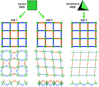
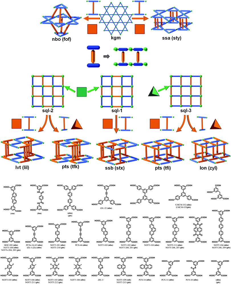
Another SBL cross-linking/pillaring method involves multifunctional ligands for linear pillaring, though perhaps in a less obvious manner. In the case of the square paddlewheel based SBLs, there are positions on the organic bridge (e.g., 5-position on isophthalate) that orient outward toward the upper and lower surfaces of the MOF layer. These sites are readily modified through conventional organic chemistry. Through appropriate design of the ligand, these positions from two neighboring layers can be chemically bridged, thus covalently pillaring the layers. In other words, specific ligands are selected/designed to simultaneously contain two bridging ligand moieties (e.g., di-isophthalate, “X”- or “I”-shaped) that pillar adjacent layers through the covalent linkage within the tetracarboxylate ligand (Fig. 30). This method of cross-linking SBLs, so called ligand-to-ligand (L–L) pillaring, where the 4-c ligand coordinates to form the 4-c paddlewheel MBB, results in 3-periodic MOFs based on an underlying (4,4)-c topology.We mentioned earlier in this review that the assembly of 4-c paddlewheels with 2-c ligands, such as isophthalates, can lead to two types of edge-transitive layers, sql or kgm. However, a close examination of the structures from the CSD,97 will reveal that it is possible to distinguish at least two types of sql layers, where the arrangement of the isophthalates around the paddlewheels differs. Taking into account the fact that the isophthalate ligand is bent, this will lead to several distinct L–L pillaring possibilities, as the functionalized position (5-position of isophthalate) of the ligand will alternately point up or down from the sql layer, but in a different fashion, as depicted in Fig. 29. This statement is generally applicable to sql layers built from paddlewheels and various ligands including isophthalate-based moieties.
A third variation can occur in the event that the 4-c node is of tetrahedral geometry. An example is by reacting salts of 6- to 8-coordinate metals (e.g., indium) and isophthalate-based ligands.191 In this manner, it is possible to target a third type of sql layer, sql-3, where the bent position of the isophthalates is alternately pointing up and down. Even though this sql-3 layer is probably more difficult to achieve compared to the ones based on paddlewheels, it allows in fine some additional interesting pillaring possibilities, as will be described later in this review.
This L–L pillaring type can be divided into two distinct subgroups, depending on the conformation of the tetracarboxylate ligand used. When the four carboxylates are arranged to form a square/rectangle, and if the SBL is based on the sql-1, or sql-2 layer, the resulting 3-periodic structures will be an ssb-MOF192 or an lvt-MOF, respectively;39 if the SBL is based on the kgm layer, the result is, in most cases, an nbo-MOF.192–196
However, other L–L pillaring types are possible but require the use of 4-c ligands with slightly different geometry. Indeed, when kgm layers are produced by bent ligands such as isophthalate, the bent/functionalizable position of the ligand does not point straightly up or down from the layer, but it is also oriented to point either inside or outside a specific window in the layer.
Depending on the orientation of the bent position, an additional topology, ssa (which can alternatively be described as sty if the 4-c ligand is considered as two 3-c nodes58), is possible.63,197 In the reported examples, the tetracarboxylate ligands are not linear, this allows the geometry to deviate from the aforementioned predefined orientation of the isophthalate moieties (similarly to the rare cases of formation of ssb-MOFs).
When the four carboxylates from the ligand form a tetrahedron (D2d symmetry; for example, two staggered isophthalates), the possible alternate pillaring of sql-2 layers will lead to MOFs with the pts topology (which can alternatively be described as tfk, if the 4-c ligand is considered as two 3-c nodes58). To the best of our knowledge, no tfk-MOFs based on pillaring of sql-2 SBLs have been reported so far.
It should be mentioned that, in addition to tuning the functionality of the ligand,192 it is also possible to tune the cavities through use of relatively low symmetry (sometimes called asymmetric due to lack of a center of inversion) ligands. Indeed, in 2010, Matzger et al. reported the synthesis of an nbo-MOF (UMCM-152) and a pts-MOF (UMCM-153), where the kgm and sql layers are of a lower symmetry (Fig. 31). For the kgm, half of the triangle windows are constructed from isophthalate moieties, whereas the other half are made from the extended isophthalate analogue, benzene-dibenzoate. Regarding the sql structure, the square shape of the windows is now modified into a rectangular shape, delimited by two isophthalate and two benzene-dibenzoate moieties.198 A similar strategy has recently been used by Qian et al. for the synthesis of an nbo-MOF (ZJU-32).199
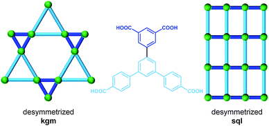 | ||
| Fig. 31 Lower symmetry ligand strategy for the formation of a pillared nbo-MOF (UMCM-152) based on the asymmetric kgm layer and a pts-MOF (UMCM-153) based on lower symmetry sql. | ||
Schröder et al. reported a series of pillared In-tetracarboxylate MOFs, where the layer is sql-3. In these cases, the two isophthalate moieties from the ligands are eclipsed, resulting in MOFs with pts topology.200–204 At this stage, it is important to notice that two different sqls (sql-2 and sql-3) can be pillared using the same type of pillaring (L–L) and lead to similar pts topology. This fact is actually due to the nature of the 4-c pts net, which results (in its augmented form) in the assembly of squares and tetrahedra. The pts net (Fig. 32) can then be regarded as (i) sql-2 layers (based on square MBBs) pillared by tetrahedra (staggered 4-c ligands), or alternatively as (ii) sql-3 layers (based on tetrahedral MBBs) pillared by square (eclipsed 4-c ligands). Interestingly, the expansion of the ligand for each case will lead to the expansion of the pts structure in two distinct ways. This difference will be well-reflected by using an alternative way of describing those structures, which consists of describing each 4-c ligand as two 3-c nodes58 and permits us to differentiate the two types of structure. Then, the pts net from sql-2 becomes a tfk net, while the pts net from sql-3 becomes a tfi net.
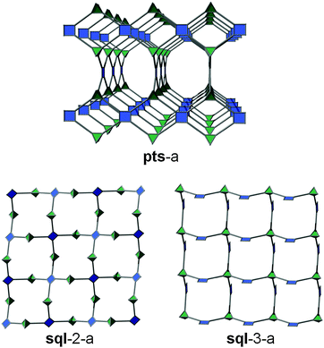 | ||
| Fig. 32 View of the pts net. It can be regarded as both sql-2 pillared by tetrahedra and sql-3 pillared by squares. | ||
The pts net is not the only one that can be achieved by L–L pillaring of sql-3. Indeed, Lah et al. recently reported a MOF where the Co2(–O2CR)4(H2O)3 MBB has the shape of a tetrahedron, which are linked together by isophthalate moieties from the ligand to form an sql-3 SBL. The second isophthalate moiety of the ligand is staggered (4-c ligand is then considered as a tetrahedron), resulting in a MOF with a very rare lon topology which can alternatively be described as zyl, if the 4-c ligand is considered as two 3-c nodes.58,204–206
3.3. eea-MOFs, rtl-MOFs, and other trigonal type pillaring
A third strategy (Fig. 33), comparable to the one previously mentioned in the SBB section for the construction of txt-MOFs, combines both of the previous two strategies through incorporating two types of function within the “linear” pillar molecule, a function that can interact with an accessible metal site on the one hand and the organic bridging ligand on the other hand. Thus, each ligand/pillar is a bi-functional ligand having trigonal geometry, containing a ditopic bridging moiety (e.g., 5-substituted isophthalate) that forms the expected MOF layer (e.g., sql or kgm),207,208 as well as a second functional group (e.g., an N-donor group attached at the 5-position of isophthalate) allowing coordination to a metal site in a neighboring layer. This combination results in what the Eddaoudi group termed ligand-to-axial (L–A) pillaring. L–A pillaring, utilizing a trigonal (3-c) pillar, produces layers composed of bridged octahedral-like MBBs (6-c) building units, Fig. 33, and thus results in the construction of (3,6)-c, 3-periodic MOFs.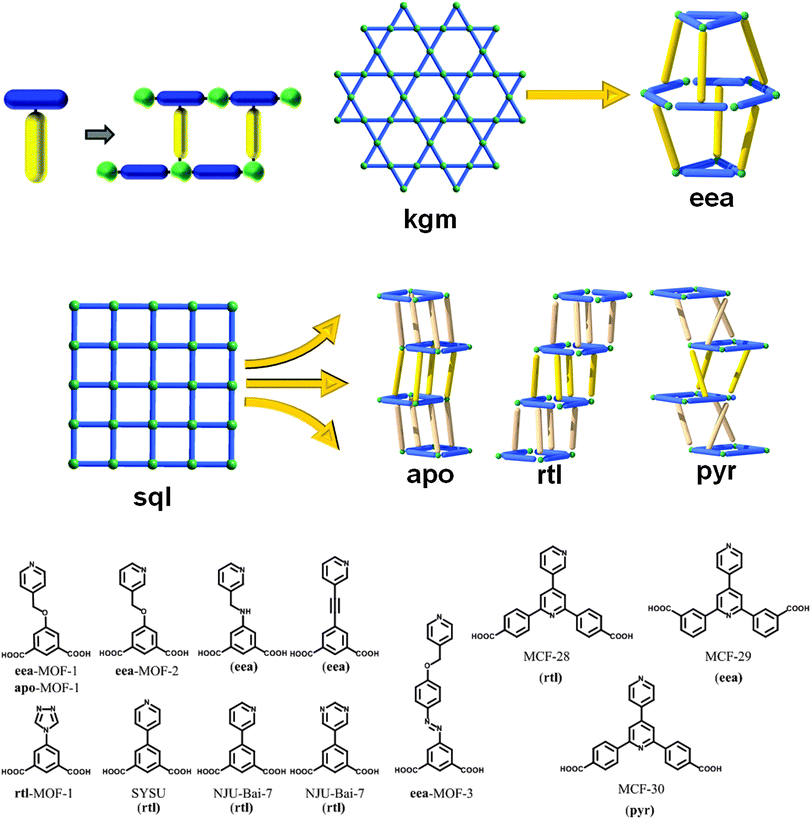 | ||
| Fig. 33 Schematic of the different L–A trigonal pillaring types successfully targeted with kgm and sql layers (top). Non-exhaustive list of ligands used for trigonal, L–A, pillaring (bottom). | ||
According to the RCSR database,9 there were fifty one reported (3,6)-c nets at the time of our research, only six of which (i.e., anh, ant, apo, brk, pyr, rtl), to our knowledge, can be deconstructed into 2D sql layers of octahedra linked by triangles (“Y”- or “T”-shaped). As such, these networks would be regarded as the most plausible targets using our strategy. The 2D layers in these targetable topologies correspond to the edge-transitive sql network, and as mentioned previously, edge-transitive nets are the most appropriate targets in crystal chemistry.
Utilizing this method, Eddaoudi and coworkers were able to design and utilize a relatively rigid bifunctional trigonal ligand, 5-(4H-1,2,4-triazol-4-yl)-isophthalic acid; reacting this ligand with copper salts allowed formation of the necessary paddlewheel MBB resulting in a targeted L–A pillared sql-MOF. Topological analysis of the resultant (3,6)-c net revealed an rtl-MOF.209 This was the expected result as the rutile net (rtl) has been considered the “easiest target for a designed synthesis” for combining triangles and octahedra.210 To the best of our knowledge, prior to this, only one similarly pillared rtl-MOF was reported, by Su et al. although no reference to pillaring was mentioned, and the topology was not assigned as rtl.211 Recent important contributions have also been reported in 2012 by Bai et al.212
To target the other (3,6)-c nets, it is possible to purposely introduce some flexibility into the pillar ligand via a methoxy linkage (e.g., 3- or 4-pyridylmethoxyisophthalic acid). This approach was reported by Eddaoudi's group to allow the intended formation of the first apo-MOF.209 Expansion of the ligand allows the synthesis of 3-periodic MOFs with larger, non-interpenetrated cavities/pores. Additionally, it is also possible to form a (3,6)-c net from the 2-periodic supramolecular isomer, kgm SBL. Though not originally listed in the RCSR database, this additional (3,6)-c net was retroactively added, resulting in the existence of the first net (eea) based on the trigonal pillaring of kgm layers.209 Notably, some isoreticular eea-MOFs, one of them now comprised of a rigid ligand, were reported by Lah et al.213,214 Finally, a recent report from Chen et al. showed the possibility to target such trigonally-pillared MOFs by using expanded layers (i.e., replacing isophthalate by pyridine-dibenzoate), including the one having pyr topology (MCF-30).215
3.4. Four-connected L–L pillars and sql layers: tbo, mmm, bor, eed, ofp, and hge nets
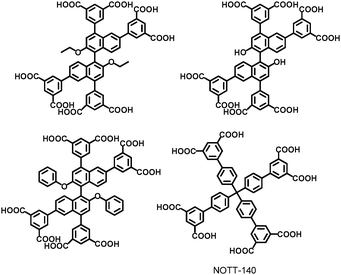
The fourth SBL approach was developed as a result of the understanding of the 3-dimensional nature of 3-periodic MOF structures and the design and development of corresponding complex multi-dimensional ligands. HKUST-1, one of the first prototype 3-periodic MOFs,216 is well-known to be a (3,4)-c structure with tbo topology (i.e., tbo-MOF) based on the trigonal (3-c) 1,3,5-BTC ligand and the square (4-c) paddlewheel dicopper MBB. Analogous or pyridyl-based expanded tbo-MOFs (based on trigonal ligands) have been widely studied,217–223 and some of them are subject to interpenetration.218,221,222Further analysis by the Eddaoudi group revealed that HKUST-1 can be deconstructed into sql layers that are cross-linked by a 4-c MBB. Thus, it can be envisioned that substitution of this MBB by analogous quadrangular organic MBBs (i.e., a non-linear, octatopic, tetrafunctional, quadrangular pillar) will allow the formation of analogous layer-based, HKUST-analogous tbo-MOFs (Fig. 34–36).
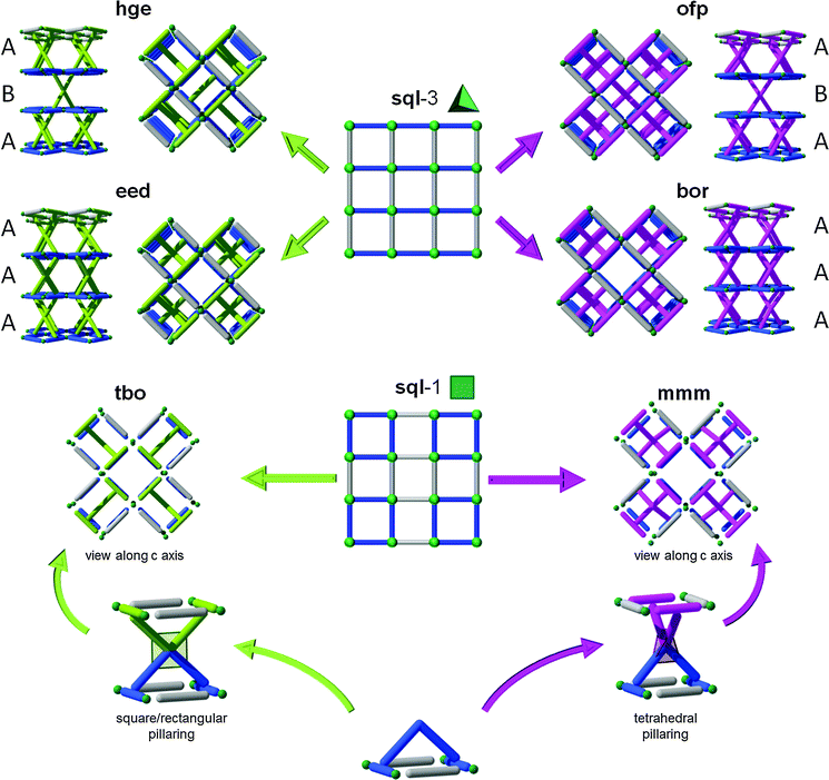 | ||
| Fig. 34 Schematic of the pillaring of sql layers by square/rectangle (left) and tetrahedral pillars (right). | ||
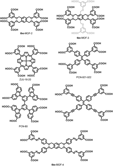 | ||
| Fig. 36 Non-exhaustive list of square/rectangle ligands utilized for the SBL formation of tbo-MOFs. Gray part of the tbo-MOF-3 ligand corresponds to non-coordinating isophthalic acid moieties. | ||
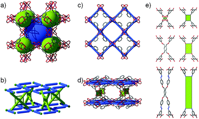
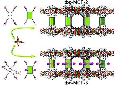
Again, the modularity of this approach allowed for the facile development of a series of isoreticular MOFs with expansion of the distance between the layers, from 11 Å in HKUST-1 up to 27 Å in tbo-MOF-4.98 Indeed, the ability to generate [M(R-BDC)]n SBLs (in this case, sql is the net-cBU) consistently in situ and space them using organic pillars permits the relatively small square windows of the SBLs to be preserved. This, unlike in the non-(SBL-based) HKUST analogues, prevents self-interpenetration, but still allows the functionalization and/or enlargement of the cavities delimited by the pillars. This is especially interesting in the case of tbo-MOF-3, where additional carboxylic acid moieties were introduced as pendant groups on the quadrangular pillar used for tbo-MOF-2, and thus permitted construction of a tbo-MOF with pores/channels decorated by a periodic array of free carboxylic acid groups (Fig. 37). This designed feature is of particular interest, because it is, in fact, quite difficult to achieve in MOFs, as carboxylic acids and/or carboxylates usually coordinate to the metals/clusters within the framework; this confirms the power of the SBL approach for the design and construction of “functional” MOFs. In addition, this functionalization in tbo-MOF-3 has an important impact on the gas sorption properties, as it allows, for example, the enhancement of the heats of adsorption for CO2 from 30 to 35 kJ mol−1,98 but also gives rise to drastically enhanced hydrocarbon separation properties.99
It should be noted that since the introduction of the SBL approach to HKUST-1-like tbo-MOFs, several other examples in the tbo-MOF family have appeared in the open literature;224–226 some of them (e.g., ZJU-18-20), however, are composed of a slightly different sql SBL, half of the square MBBs forming the sql layer being a 4-c Mn3(–O2CR)4(μ-H2O) trimer instead of the usual M2(–O2CR)4 paddlewheel.227
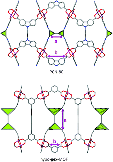
Another interesting example is illustrated by PCN-80. Indeed, this MOF is a tbo-MOF, but unlike most of the other examples, its “fully deconstructed” topology can be interpreted as a (3,3,4)-c net with lwg topology. Surprisingly, in this MOF/net, distance between the triangles (denoted “a” in Fig. 38) is closely related to the distance between the two carboxylates on each arm of the ligand (denoted “b”), which makes further expansion of the ligand very difficult, if not impossible in PCN-80, whereas ligand expansion is an easily achievable feature in some of the other reported tbo-MOFs.98 However, one can imagine a net related to tbo, in which the deconstruction of the square/rectangle into two triangles58 leads to a distance “a” independent from the distance “b”, making therefore the hypothetical MOFs obtained in this net expandable on the “a” distance without restriction of the “b” distance. We envisioned such a (3,3,4)-c net with transitivity [3333] (coordination sequence for each node: A: 4 8 16 24 42 64 84 108 132 174; B: 3 6 14 27 42 55 78 120 149 156; C: 3 8 13 24 38 59 81 102 135 167) and named it gex.
The second possible complex pillaring of sql SBLs (i.e., by a tetragonal pillar) can be achieved by switching from square/rectangle pillar geometry to a geometrically tetrahedral pillar type, which will afford MOFs with mmm topology (Fig. 34 and Fig. 39). Lin et al. reported in 2009 the first examples of such a pillared mmm-MOF (which can be alternatively described as mml topology, while considering the tetrahedral shape as two staggered 3-c nodes58).228 Since this early report, which did not refer to layers or pillaring, only a few more recent examples of mmm-MOFs have been reported, indicating that this pillaring type still lends to further exploration.229,230
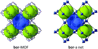
The two previous types of pillaring are achieved using the sql layer denoted sql-1 in Fig. 29. Of course, there might be other possible ways to pillar sql layers using squares or triangles that will involve sql-2. Due to the lack of information present in the literature, sql-2 will not be discussed further in this review. However, another famous topology, namely boracite (bor), can, as the names suggest, be seen as related to tbo (twisted boracite). Using our SBL approach, it is obvious that MOFs having bor topology can be achieved through tetrahedral pillaring of sql-3.
Though it may not be the SBL approach, it is worth mentioning (in a review on SBBs as well) that the networks with both tbo and bor topologies can also be seen as based on the edge-center-shared tetrahedral MOPs (Fig. 40). While the shared edge-center in tbo net is a planar 4-c node of D2h point symmetry, the corresponding shared edge-center in the bor net is a tetrahedral 4-c node of D2d point symmetry.
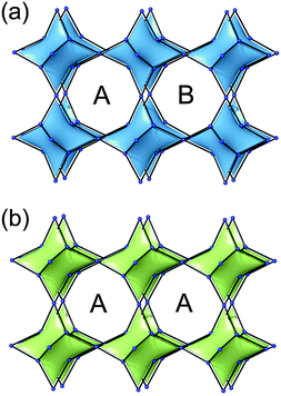 | ||
| Fig. 40 A comparison of the two (3,4)-c nets with (a) tbo topology and (b) bor topology based on edge-center-shared tetrahedral MOPs. | ||
Several MOFs with the bor topology have been reported (Fig. 41),231–236 but, to the best of our knowledge, there are only a limited number of bor-MOFs where the net is constructed from the pillaring of sql-3 by tetrahedra, that is, MOFs where the tetrahedra form the sql are distinct from the tetrahedra that serve as pillars (i.e., only a few SBL-based bor-MOFs).237,238
Interestingly, and comparable to the case of rtl and apo nets (Fig. 33), two distinct ways are possible for this type of pillaring of sql-3, leading to a second topology, namely ofp.239 This ofp net can be regarded as A-B-A pillaring of sqls, whereas the bor net is of the A-A-A pillaring type (Fig. 34). Since the ofp net is not an edge-transitive net, it is not as favorable in crystal chemitry and is less likely to be observed than the bor net.
Similar to the case of tbo and mmm from sql-1, not only can the sql-3 layer be pillared by tetrahedra, as described above, but also by squares/rectangles. Likewise, two distinct ways are possible for this type of pillaring, leading to two distinct (3,4,4)-c nets that had not been reported prior to this review. The first topology, now added to the RCSR as eed, corresponds to a (3,4,4)-c net with transitivity [3221] (coordination sequence for each node: A: 3 9 15 33 45 82 90 153 150 230; B: 4 8 20 30 60 68 120 126 200 180; C: 4 8 20 30 60 68 120 126 200 180) and consists of A-A-A pillaring, whereas the second topology, hge corresponds to a (3,4,4)-c net with transitivity [3221] (coordination sequence for each node: A: 3 9 15 33 44 80 86 147 142 229; B: 4 8 20 28 56 68 120 110 184 188; C: 4 8 20 30 60 64 112 118 192 172) and A-B-A pillaring (Fig. 34). At the time of our research, no MOFs having these topologies have been reported, but there is no doubt such MOFs can be reasonably targeted and achieved using the SBL approach and the appropriate metal–ligand systems.240
3.5. Six-connected L–L pillars and kgm layers: agw and eef nets
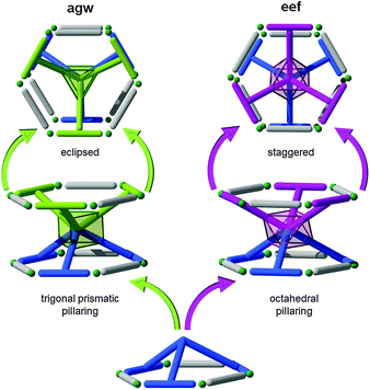
Due to the symmetry of the quadrangular- and tetrahedral-core pillars, kgm layers (with triangular and hexagonal pores) have been precluded from the previous two examples of the SBL approach. Nonetheless, kgm SBLs can also be utilized to target 3-periodic MOFs with multi-dimensional ligands of different symmetry (e.g., Oh and D3h). There are two common types of 6-c node, octahedral and trigonal prism, which could serve as a multi-connected pillar between kgm layers. If we explore the paddlewheel-based kgm-MOF, one can envision how a hexa-isophthalate ligand or metalloligand (3-up, 3-down) might serve the purpose to target pillared kgm-MOFs. While the isophthalates, in combination with the M2(–O2CR)4 dinuclear paddlewheel cluster, generate the two-periodic kgm SBL, functionalization in the isophthalate 5-position, either through covalent linkage to a 6-c organic core (e.g., hexa-substituted benzene) or to an ancillary function that can coordinate to a 6-c metal/cluster (e.g., metalloligand), offers the potential to generate numerous cross-linked kgm-MOFs (Fig. 42).A review of the CSD97 reveals that hexa-substituted benzenes often give a 3-up, 3-down orientation of the external groups. Thus, the design and synthesis of a hexa-isophthalate ligand, similar to the one used for the carboxylate-functionalized tbo-MOF-3, has the potential to give an octahedral organic core, covalently linking each of the six isophthalate termini resulting in an octahedral orientation; this feature combined with the kgm SBL results in a net with the recently added eef topology.240
Alternatively, the pillaring of kgm through a trigonal prismatic core results in a net having agw topology (i.e., agw-MOFs). Though obviously predictable via the SBL approach, this type of structure was first discovered serendipitously by employing lower symmetry tricarboxylate (i.e., pseudo-heterofunctional) ligands in combination with metals suitable for formation of the dinuclear paddlewheel MBB (e.g., copper). However, an additional MBB, an unexpected trinuclear cluster, formed in situ, which, in combination with the ligand, mimics a trigonal prism hexa-isophthalate ligand, and, with the paddlewheel, this “metalloligand” gave rise to the corresponding pillared kgm-MOF, an agw-MOF. To the best of our knowledge, no reference to any pillaring technique was mentioned.241 Similar materials have since been retroactively targeted and achieved by utilizing a mixed-metal system, where a secondary metal (copper being the primary metal which forms the paddlewheel and the SBLs) is utilized to form a trinuclear trigonal prism cluster MBB as the core of the metalloligand pillar.242
3.6. Six-connected A–A pillars and kgm layers: lon-e net
As the last example of pillared MOFs using the SBL strategy (A–A fashion, Fig. 43), Zaworotko et al. recently developed a stepwise path for the achievement of a similar type of pillaring.243 Rather than targeting conditions to form the requisite trigonal prism in situ, their group developed relatively stable trinuclear trigonal prism clusters (i.e., discrete) from chromium salts with the formula Cr3(μ3O)(–O2CR)6, decorated by six pyridyl moieties. They were then able to target the kgm SBL in situ for the construction of a series of pillared MOFs with lon-e topology. This method broadens the scope of the SBL approach and pillaring strategies toward the design of functional materials.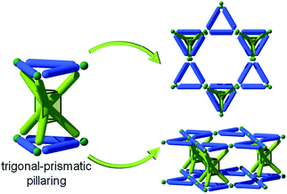 | ||
| Fig. 43 Schematic showing the possible axial-to-axial (A–A) pillaring of kgm layers by trigonal prism pillars, leading to lon-e topology. | ||
3.7. Layers for MOFs: Conclusion
As demonstrated above, the SBL approach relies on the use of a metal–organic layer, usually based on edge-transitive lattices (e.g., Kagomé and square), as an elaborate building entity (the net-cBU, in this case) that is then periodically cross-linked (pillared) into predicted three-periodic MOFs. Once the net-cBU is established, pillaring can be targeted via three different methods, depending on the the SBL and respective geometry (e.g., bridging ligand orientation): (1) Axial-to-axial (A–A); (2) axial-to-ligand (A–L); and (3) ligand-to-ligand (L–L), which can be subdivided into simple (e.g., linear) or complex (e.g., multi-dimensional). As in the case of SBBs, the key prerequisites to use the SBL approach for the design of a MOF are: (1) A blueprint net with minimal edge-transitivity, preferably singular, that is exclusive for the particular pillaring of the given building units, and (2) reaction conditions that permit us to consistently form the desired SBL in situ. Uniquely, control of the SBL pores allows the material designer to preclude self-interpenetration upon net expansion and/or decoration, leading to predicted and unprecedented MOFs with tunable cavities, essentially isoreticular platforms that can be ideally functionalized for pressing applications pertaining to catalysis and gas separation.4. Conclusions
In this review, we described and illustrated two powerful design strategies, namely the SBB and SBL approaches. Without being exhaustive, we carefully selected relevant examples that should guide researchers and show them how judicious selection of pre-programmed SBBs or SBLs allows for the construction of pre-designed MOFs.Although topological considerations are of prime importance to describe the structure, we encourage chemists to use the tools of topology (net, connectivity, edge-transitivity, minimal transitivity) to elucidate the ideal SBBs or SBLs with all the coded structural/geometrical information that will serve as net-cBUs to construct the desired MOFs.
To illustrate these methodologies, we described some topologies for which MOFs have already been reported, but also proposed some new ideas (i.e., some unprecedented topologies) that have not yet been explored. There is no doubt they are attainable targets in MOF chemistry, as they are envisioned from the assembly of already existing SBLs or SBBs.
Finally, using an ideal blueprint, in combination with the appropriate pre-programmed SBB or SBL, design almost becomes a reality, and the only limitation for the construction of the desired functional MOFs is the chemist/material designer's imagination.
Acknowledgements
This work was supported by the King Abdullah University of Science and Technology (KAUST). NRF-2010-0019408 and NRF-2012R1A2A2A01003077 through the National Research Foundation of Korea.Notes and references
- M. Eddaoudi, D. B. Moler, H. L. Li, B. L. Chen, T. M. Reineke, M. O'Keeffe and O. M. Yaghi, Acc. Chem. Res., 2001, 34, 319–330 CrossRef CAS PubMed.
- G. Férey, Chem. Soc. Rev., 2008, 37, 191–214 RSC.
- Z.-J. Lin, J. Lu, M. Hong and R. Cao, Chem. Soc. Rev., 2014 10.1039/c4cs00003j.
- W. Lu, Z. Wei, Z.-Y. Gu, T.-F. Liu, J. Park, J. Park, J. Tian, M. Zhang, Q. Zhang, T. Gentle Iii, M. Bosch and H.-C. Zhou, Chem. Soc. Rev., 2014 10.1039/c4cs00041b.
- M. Eddaoudi, J. Kim, N. Rosi, D. Vodak, J. Wachter, M. O'Keeffe and O. M. Yaghi, Science, 2002, 295, 469–472 CrossRef CAS PubMed.
- S. M. Cohen, Chem. Rev., 2012, 112, 970–1000 CrossRef CAS PubMed.
- J. R. Long, O. M. Yaghi, (ed.) Chem. Soc. Rev., 2009, 38, 1201–1508.
- H. C. Zhou, J. R. Long, O. M. Yaghi, (ed.) Chem. Rev., 2012, 112, 673–1268.
- M. O'Keeffe, M. A. Peskov, S. J. Ramsden and O. M. Yaghi, Acc. Chem. Res., 2008, 41, 1782–1789 CrossRef PubMed.
- V. Guillerm, Ł. J. Weselinski, Y. Belmabkhout, A. J. Cairns, V. D'Elia, Ł. Wojtas, K. Adil and M. Eddaoudi, Nat. Chem., 2014 DOI:10.1038/NCHEM.1982.
- D.-X. Xue, A. J. Cairns, Y. Belmabkhout, L. Wojtas, Y. Liu, M. H. Alkordi and M. Eddaoudi, J. Am. Chem. Soc., 2013, 135, 7660–7667 CrossRef CAS PubMed.
- J. F. Eubank, F. Nouar, R. Luebke, A. J. Cairns, L. Wojtas, M. Alkordi, T. Bousquet, M. R. Hight, J. Eckert, J. P. Embs, P. A. Georgiev and M. Eddaoudi, Angew. Chem., Int. Ed., 2012, 51, 10099–10103 CrossRef CAS PubMed.
- F. Nouar, J. F. Eubank, T. Bousquet, L. Wojtas, M. J. Zaworotko and M. Eddaoudi, J. Am. Chem. Soc., 2008, 130, 1833–1834 CrossRef CAS PubMed.
- W. Morris, B. Volosskiy, S. Demir, F. Gandara, P. L. McGrier, H. Furukawa, D. Cascio, J. F. Stoddart and O. M. Yaghi, Inorg. Chem., 2012, 51, 6443–6445 CrossRef CAS PubMed.
- J. H. Cavka, S. Jakobsen, U. Olsbye, N. Guillou, C. Lamberti, S. Bordiga and K. P. Lillerud, J. Am. Chem. Soc., 2008, 130, 13850–13851 CrossRef PubMed.
- V. Guillerm, S. Gross, C. Serre, T. Devic, M. Bauer and G. Férey, Chem. Commun., 2010, 46, 767–769 RSC.
- V. Guillerm, F. Ragon, M. Dan-Hardi, T. Devic, M. Vishnuvarthan, B. Campo, A. Vimont, G. Clet, Q. Yang, G. Maurin, G. Férey, A. Vittadini, S. Gross and C. Serre, Angew. Chem., Int. Ed., 2012, 51, 9267–9271 CrossRef CAS PubMed.
- M. Dan-Hardi, C. Serre, T. Frot, L. Rozes, G. Maurin, C. Sanchez and G. Férey, J. Am. Chem. Soc., 2009, 131, 10857–10859 CrossRef CAS PubMed.
- D.-Y. Du, J.-S. Qin, Z. Sun, L.-K. Yan, M. O'Keeffe, Z.-M. Su, S.-L. Li, X.-H. Wang, X.-L. Wang and Y.-Q. Lan, Sci. Rep., 2013, 3, 2616 Search PubMed.
- R. Luebke, J. F. Eubank, A. J. Cairns, Y. Belmabkhout, L. Wojtas and M. Eddaoudi, Chem. Commun., 2012, 48, 1455–1457 RSC.
- R. Luebke, Ł. J. Weseliński, Y. Belmabkhout, Z. Chen, Ł. Wojtas and M. Eddaoudi, Cryst. Growth Des., 2014, 14, 414–418 CAS.
- U. Stoeck, S. Krause, V. Bon, I. Senkovska and S. Kaskel, Chem. Commun., 2012, 48, 10841–10843 RSC.
- A. J. Cairns, J. A. Perman, L. Wojtas, V. C. Kravtsov, M. H. Alkordi, M. Eddaoudi and M. J. Zaworotko, J. Am. Chem. Soc., 2008, 130, 1560–1561 CrossRef CAS PubMed.
- M. Eddaoudi, J. F. Eubank, F. Nouar, Ł. Wojtas, T. Bousquet and M. J. Zaworotko, US2009143596-A1, US8034952-B2, 2009 Search PubMed.
- Y. L. Liu, V. Kravtsov, R. D. Walsh, P. Poddar, H. Srikanth and M. Eddaoudi, Chem. Commun., 2004, 2806–2807 RSC.
- M. H. Alkordi, J. A. Brant, L. Wojtas, V. C. Kravtsov, A. J. Cairns and M. Eddaoudi, J. Am. Chem. Soc., 2009, 131, 17753–17755 CrossRef CAS PubMed.
- M. O'Keeffe and O. M. Yaghi, Chem. Rev., 2012, 112, 675–702 CrossRef PubMed.
- M. Li, D. Li, M. O'Keeffe and O. M. Yaghi, Chem. Rev., 2014, 114, 1343–1370 CrossRef CAS PubMed.
- N. W. Ockwig, O. Delgado-Friedrichs, M. O'Keeffe and O. M. Yaghi, Acc. Chem. Res., 2005, 38, 176–182 CrossRef CAS PubMed.
- D. J. Tranchemontagne, J. L. Mendoza-Cortes, M. O'Keeffe and O. M. Yaghi, Chem. Soc. Rev., 2009, 38, 1257–1283 RSC.
- M. Eddaoudi, J. Kim, D. Vodak, A. Sudik, J. Wachter, M. O'Keeffe and O. M. Yaghi, Proc. Natl. Acad. Sci. U. S. A., 2002, 99, 4900–4904 CrossRef CAS PubMed.
- J. Bunzen, J. Iwasa, P. Bonakdarzadeh, E. Numata, K. Rissanen, S. Sato and M. Fujita, Angew. Chem., Int. Ed., 2012, 51, 3161–3163 CrossRef CAS PubMed.
- Q.-F. Sun, J. Iwasa, D. Ogawa, Y. Ishido, S. Sato, T. Ozeki, Y. Sei, K. Yamaguchi and M. Fujita, Science, 2010, 328, 1144–1147 CrossRef CAS PubMed.
- M. Eddaoudi, J. Kim, J. B. Wachter, H. K. Chae, M. O'Keeffe and O. M. Yaghi, J. Am. Chem. Soc., 2001, 123, 4368–4369 CrossRef CAS.
- B. Moulton, J. J. Lu, A. Mondal and M. J. Zaworotko, Chem. Commun., 2001, 863–864 RSC.
- Z. Ni, A. Yassar, T. Antoun and O. M. Yaghi, J. Am. Chem. Soc., 2005, 127, 12752–12753 CrossRef CAS PubMed.
- J.-R. Li, A. A. Yakovenko, W. Lu, D. J. Timmons, W. Zhuang, D. Yuan and H.-C. Zhou, J. Am. Chem. Soc., 2010, 132, 17599–17610 CrossRef CAS PubMed.
- J.-R. Li, D. J. Timmons and H.-C. Zhou, J. Am. Chem. Soc., 2009, 131, 6368–6369 CrossRef CAS PubMed.
- H. Furukawa, J. Kim, N. W. Ockwig, M. O'Keeffe and O. M. Yaghi, J. Am. Chem. Soc., 2008, 130, 11650–11661 CrossRef CAS PubMed.
- J.-R. Li and H.-C. Zhou, Angew. Chem., Int. Ed., 2009, 48, 8465–8468 CrossRef CAS PubMed.
- T. R. Cook, Y.-R. Zheng and P. J. Stang, Chem. Rev., 2013, 113, 734–777 CrossRef CAS PubMed.
- R. Chakrabarty, P. S. Mukherjee and P. J. Stang, Chem. Rev., 2011, 111, 6810–6918 CrossRef CAS PubMed.
- J. J. Perry, J. A. Perman and M. J. Zaworotko, Chem. Soc. Rev., 2009, 38, 1400–1417 RSC.
- A. C. Sudik, A. R. Millward, N. W. Ockwig, A. P. Côté, J. Kim and O. M. Yaghi, J. Am. Chem. Soc., 2005, 127, 7110–7118 CrossRef CAS PubMed.
- A. C. Sudik, A. P. Côté, A. G. Wong-Foy, M. O'Keeffe and O. M. Yaghi, Angew. Chem., Int. Ed., 2006, 45, 2528–2533 CrossRef CAS PubMed.
- G. Férey, C. Serre, C. Mellot-Draznieks, F. Millange, S. Surblé, J. Dutour and I. Margiolaki, Angew. Chem., Int. Ed., 2004, 43, 6296–6301 CrossRef PubMed.
- G. Férey, C. Mellot-Draznieks, C. Serre, F. Millange, J. Dutour, S. Surblé and I. Margiolaki, Science, 2005, 309, 2040–2042 CrossRef PubMed.
- A. Sonnauer, F. Hoffmann, M. Froeba, L. Kienle, V. Duppel, M. Thommes, C. Serre, G. Férey and N. Stock, Angew. Chem., Int. Ed., 2009, 48, 3791–3794 CrossRef CAS PubMed.
- H. Chevreau, T. Devic, F. Salles, G. Maurin, N. Stock and C. Serre, Angew. Chem., Int. Ed., 2013, 52, 5056–5060 CrossRef CAS PubMed.
- C. Mellot-Draznieks, J. Dutour and G. Férey, Z. Anorg. Allg. Chem., 2004, 630, 2599–2604 CrossRef CAS.
- M. H. Alkordi, J. L. Belof, E. Rivera, L. Wojtas and M. Eddaoudi, Chem. Sci., 2011, 2, 1695–1705 RSC.
- D. F. Sava, V. C. Kravtsov, J. Eckert, J. F. Eubank, F. Nouar and M. Eddaoudi, J. Am. Chem. Soc., 2009, 131, 10394–10395 CrossRef CAS PubMed.
- O. Delgado-Friedrichs, M. O'Keeffe and O. M. Yaghi, Acta Crystallogr., Sect. A: Found. Crystallogr., 2006, 62, 350–355 CrossRef PubMed.
- R.-Q. Zou, H. Sakurai and Q. Xu, Angew. Chem., Int. Ed., 2006, 45, 2542–2546 CrossRef CAS PubMed.
- T. Wu, X. Bu, J. Zhang and P. Feng, Chem. Mater., 2008, 20, 7377–7382 CrossRef CAS.
- J.-Z. Chen, Y.-G. Tu, X.-L. Nie and H.-L. Wen, Chin. J. Synth. Chem., 2011, 19, 359 CAS.
- Y. Liu, V. Ch. Kravtsov, D. A. Beauchamp, J. F. Eubank and M. Eddaoudi, J. Am. Chem. Soc., 2005, 127, 7266–7267 CrossRef CAS PubMed.
- J. F. Eubank, R. D. Walsh, P. Poddar, H. Srikanth, R. W. Larsen and M. Eddaoudi, Cryst. Growth Des., 2006, 6, 1453–1457 CAS.
- M. O'Keeffe and B. G. Hyde, Mineralogical Society of America, Washington, DC, 1996 Search PubMed.
- J. J. Perry, V. C. Kravtsov, G. J. McManus and M. J. Zaworotko, J. Am. Chem. Soc., 2007, 129, 10076–10077 CrossRef CAS PubMed.
- C. Li, W. Qiu, W. Shi, H. Song, G. Bai, H. He, J. Li and M. J. Zaworotko, CrystEngComm, 2012, 14, 1929 RSC.
- X. Liu, M. Park, S. Hong, M. Oh, J. W. Yoon, J.-S. Chang and M. S. Lah, Inorg. Chem., 2009, 48, 11507–11509 CrossRef CAS PubMed.
- X.-S. Wang, S. Ma, P. M. Forster, D. Yuan, J. Eckert, J. J. López, B. J. Murphy, J. B. Parise and H.-C. Zhou, Angew. Chem., Int. Ed., 2008, 47, 7263–7266 CrossRef CAS PubMed.
- G. J. McManus, Z. Q. Wang and M. J. Zaworotko, Cryst. Growth Des., 2004, 4, 11–13 CAS.
- H. Chun, J. Am. Chem. Soc., 2008, 130, 800–801 CrossRef CAS PubMed.
- H. Chun, H. Jung and J. Seo, Inorg. Chem., 2009, 48, 2043–2047 CrossRef CAS PubMed.
- H.-N. Wang, X. Meng, G.-S. Yang, X.-L. Wang, K.-Z. Shao, Z.-M. Su and C.-G. Wang, Chem. Commun., 2011, 47, 7128–7130 RSC.
- O. Delgado-Friedrichs and M. O'Keeffe, Acta Crystallogr., Sect. A: Found. Crystallogr., 2007, 63, 344–347 CrossRef CAS PubMed.
- Y. Zou, M. Park, S. Hong and M. S. Lah, Chem. Commun., 2008, 2340–2342 RSC.
- B. Li, Z. Zhang, Y. Li, K. Yao, Y. Zhu, Z. Deng, F. Yang, X. Zhou, G. Li, H. Wu, N. Nijem, Y. J. Chabal, Z. Lai, Y. Han, Z. Shi, S. Feng and J. Li, Angew. Chem., Int. Ed., 2012, 51, 1412–1415 CrossRef CAS PubMed.
- D. Yuan, D. Zhao, D. Sun and H.-C. Zhou, Angew. Chem., Int. Ed., 2010, 49, 5357–5361 CrossRef CAS PubMed.
- D. Fairen-Jimenez, Y. J. Colon, O. K. Farha, Y.-S. Bae, J. T. Hupp and R. Q. Snurr, Chem. Commun., 2012, 48, 10496–10498 RSC.
- S. Hong, M. Oh, M. Park, J. W. Yoon, J.-S. Chang and M. S. Lah, Chem. Commun., 2009, 5397–5399 RSC.
- Y. Peng, G. Srinivas, C. E. Wilmer, I. Eryazici, R. Q. Snurr, J. T. Hupp, T. Yildirim and O. K. Farha, Chem. Commun., 2013, 49, 2992–2994 RSC.
- Y. Yan, X. Lin, S. Yang, A. J. Blake, A. Dailly, N. R. Champness, P. Hubberstey and M. Schroeder, Chem. Commun., 2009, 1025–1027 RSC.
- Y. Yan, S. Yang, A. J. Blake, W. Lewis, E. Poirier, S. A. Barnett, N. R. Champness and M. Schroeder, Chem. Commun., 2011, 47, 9995–9997 RSC.
- B. Zheng, Z. Yang, J. Bai, Y. Li and S. Li, Chem. Commun., 2012, 48, 7025–7027 RSC.
- D. Ma, B. Li, X. Zhou, Q. Zhou, K. Liu, G. Zeng, G. Li, Z. Shi and S. Feng, Chem. Commun., 2013, 49, 8964–8966 RSC.
- Y. Yan, A. J. Blake, W. Lewis, S. A. Barnett, A. Dailly, N. R. Champness and M. Schroeder, Chem. – Eur. J., 2011, 17, 11162–11170 CrossRef CAS PubMed.
- I. Eryazici, O. K. Farha, B. G. Hauser, A. O. Yazaydin, A. A. Sarjeant, S. T. Nguyen and J. T. Hupp, Cryst. Growth Des., 2012, 12, 1075–1080 CAS.
- W. Wei, W. Li, X. Wang and J. He, Cryst. Growth Des., 2013, 13, 3843–3846 CAS.
- D. Yuan, D. Zhao and H.-C. Zhou, Inorg. Chem., 2011, 50, 10528–10530 CrossRef CAS PubMed.
- O. K. Farha, I. Eryazici, N. C. Jeong, B. G. Hauser, C. E. Wilmer, A. A. Sarjeant, R. Q. Snurr, S. T. Nguyen, A. Ö. Yazaydın and J. T. Hupp, J. Am. Chem. Soc., 2012, 134, 15016–15021 CrossRef CAS PubMed.
- C. E. Wilmer, O. K. Farha, T. Yildirim, I. Eryazici, V. Krungleviciute, A. A. Sarjeant, R. Q. Snurr and J. T. Hupp, Energy Environ. Sci., 2013, 6, 1158–1163 CAS.
- G. Barin, V. Krungleviciute, D. A. Gomez-Gualdron, A. A. Sarjeant, R. Q. Snurr, J. T. Hupp, T. Yildirim and O. K. Farha, Chem. Mater., 2014, 26, 1912–1917 CrossRef CAS.
- O. K. Farha, I. Eryazici, N. C. Jeong, B. G. Hauser, C. E. Wilmer, A. A. Sarjeant, R. Q. Snurr, S. T. Nguyen, A. Ö. Yazaydin and J. T. Hupp, J. Am. Chem. Soc., 2012, 134, 15016–15021 CrossRef CAS PubMed.
- O. K. Farha, A. O. Yazaydin, I. Eryazici, C. D. Malliakas, B. G. Hauser, M. G. Kanatzidis, S. T. Nguyen, R. Q. Snurr and J. T. Hupp, Nat. Chem., 2010, 2, 944–948 CrossRef CAS PubMed.
- P. Zhang, B. Li, Y. Zhao, X. Meng and T. Zhang, Chem. Commun., 2011, 47, 7722–7724 RSC.
- J. Park, J. R. Li, Y. P. Chen, J. Yu, A. A. Yakovenko, Z. U. Wang, L. B. Sun, P. B. Balbuena and H. C. Zhou, Chem. Commun., 2012, 48, 9995–9997 RSC.
- T.-T. Lian, S.-M. Chen, F. Wang and J. Zhang, CrystEngComm, 2013, 15, 1036–1038 RSC.
- J. Park, S. Hong, D. Moon, M. Park, K. Lee, S. Kang, Y. Zou, R. P. John, G. H. Kim and M. S. Lah, Inorg. Chem., 2007, 46, 10208–10213 CrossRef CAS PubMed.
- Z.-J. Zhang, W. Shi, Z. Niu, H.-H. Li, B. Zhao, P. Cheng, D.-Z. Liao and S.-P. Yan, Chem. Commun., 2011, 47, 6425–6427 RSC.
- X. Zhao, X. Wang, S. Wang, J. Dou, P. Cui, Z. Chen, D. Sun, X. Wang and D. Sun, Cryst. Growth Des., 2012, 12, 2736–2739 CAS.
- X.-R. Hao, X.-L. Wang, K.-Z. Shao, G.-S. Yang, Z.-M. Su and G. Yuan, CrystEngComm, 2012, 14, 5596–5603 RSC.
- J. J. Lu, A. Mondal, B. Moulton and M. J. Zaworotko, Angew. Chem., Int. Ed., 2001, 40, 2113–2116 CrossRef CAS.
- H. Li, M. Eddaoudi, T. L. Groy and O. M. Yaghi, J. Am. Chem. Soc., 1998, 120, 8571–8572 CrossRef CAS.
- F. H. Allen, Acta Cryst., 2002, B58, 380–388 CrossRef CAS PubMed.
- J. F. Eubank, H. Mouttaki, A. J. Cairns, Y. Belmabkhout, L. Wojtas, R. Luebke, M. Alkordi and M. Eddaoudi, J. Am. Chem. Soc., 2011, 133, 14204–14207 CrossRef CAS PubMed.
- Y. Belmabkhout, J. F. Eubank, V. Guillerm, H. Mouttaki and M. Eddaoudi, 2014, submitted.
- C. G. Carson, K. Hardcastle, J. Schwartz, X. Liu, C. Hoffmann, R. A. Gerhardt and R. Tannenbaum, Eur. J. Inorg. Chem., 2009, 2338–2343 CrossRef CAS.
- K. Seki, S. Takamizawa and W. Mori, Chem. Lett., 2001, 30, 332–333 CrossRef.
- S. Henke, A. Schneemann, A. Wütscher and R. A. Fischer, J. Am. Chem. Soc., 2012, 134, 9464–9474 CrossRef CAS PubMed.
- R. Kitaura, F. Iwahori, R. Matsuda, S. Kitagawa, Y. Kubota, M. Takata and T. C. Kobayashi, Inorg. Chem., 2004, 43, 6522–6524 CrossRef CAS PubMed.
- S. Henke, R. Schmid, J.-D. Grunwaldt and R. A. Fischer, Chem. – Eur. J., 2010, 16, 14296–14306 CrossRef CAS PubMed.
- K. Uemura, Y. Yamasaki, Y. Komagawa, K. Tanaka and H. Kita, Angew. Chem., Int. Ed., 2007, 46, 6662–6665 CrossRef CAS PubMed.
- K. Uemura, F. Onishi, Y. Yamasaki and H. Kita, J. Solid State Chem., 2009, 182, 2852–2857 CrossRef CAS PubMed.
- L.-G. Zhu and H.-P. Xiao, Z. Anorg. Allg. Chem., 2008, 634, 845–847 CrossRef CAS.
- S. Furukawa, K. Hirai, K. Nakagawa, Y. Takashima, R. Matsuda, T. Tsuruoka, M. Kondo, R. Haruki, D. Tanaka, H. Sakamoto, S. Shimomura, O. Sakata and S. Kitagawa, Angew. Chem., Int. Ed., 2009, 48, 1766–1770 CrossRef CAS PubMed.
- P. Maniam and N. Stock, Inorg. Chem., 2011, 50, 5085–5097 CrossRef CAS PubMed.
- J. Y. Lee, D. H. Olson, L. Pan, T. J. Emge and J. Li, Adv. Funct. Mater., 2007, 17, 1255–1262 CrossRef CAS.
- Y. Zhao, H. Wu, T. J. Emge, Q. Gong, N. Nijem, Y. J. Chabal, L. Kong, D. C. Langreth, H. Liu, H. Zeng and J. Li, Chem. – Eur. J., 2011, 17, 5101–5109 CrossRef CAS PubMed.
- K. Hirai, S. Furukawa, M. Kondo, H. Uehara, O. Sakata and S. Kitagawa, Angew. Chem., Int. Ed., 2011, 50, 8057–8061 CrossRef CAS PubMed.
- H. Chun, D. N. Dybtsev, H. Kim and K. Kim, Chem. – Eur. J., 2005, 11, 3521–3529 CrossRef CAS PubMed.
- K. Hirai, S. Furukawa, M. Kondo, M. Meilikhov, Y. Sakata, O. Sakata and S. Kitagawa, Chem. Commun., 2012, 48, 6472–6474 RSC.
- D. Tanaka, S. Horike, S. Kitagawa, M. Ohba, M. Hasegawa, Y. Ozawa and K. Toriumi, Chem. Commun., 2007, 3142–3144 RSC.
- K. Uemura, Y. Yamasaki, F. Onishi, H. Kita and M. Ebihara, Inorg. Chem., 2010, 49, 10133–10143 CrossRef CAS PubMed.
- Z. Chen, S. Xiang, H. D. Arman, P. Li, D. Zhao and B. Chen, Eur. J. Inorg. Chem., 2011, 2227–2231 CrossRef CAS.
- H. Kim, D. G. Samsonenko, S. Das, G.-H. Kim, H.-S. Lee, D. N. Dybtsev, E. A. Berdonosova and K. Kim, Chem. – Asian J., 2009, 4, 886–891 CrossRef CAS PubMed.
- M. Kim, J. A. Boissonnault, P. V. Dau and S. M. Cohen, Angew. Chem., Int. Ed., 2011, 50, 12193–12196 CrossRef CAS PubMed.
- K. Li, J. Lee, D. H. Olson, T. J. Emge, W. Bi, M. J. Eibling and J. Li, Chem. Commun., 2008, 6123–6125 RSC.
- H. Wang, J. Getzschmann, I. Senkovska and S. Kaskel, Microporous Mesoporous Mater., 2008, 116, 653–657 CrossRef CAS PubMed.
- D. N. Dybtsev, H. Chun and K. Kim, Angew. Chem., Int. Ed., 2004, 43, 5033–5036 CrossRef CAS PubMed.
- H. Chun and J. Moon, Inorg. Chem., 2007, 46, 4371–4373 CrossRef CAS PubMed.
- Z. Chen, S. Xiang, D. Zhao and B. Chen, Cryst. Growth Des., 2009, 9, 5293–5296 CAS.
- O. Kozachuk, K. Khaletskaya, M. Halbherr, A. Bétard, M. Meilikhov, R. W. Seidel, B. Jee, A. Pöppl and R. A. Fischer, Eur. J. Inorg. Chem., 2012, 1688–1695 CrossRef CAS.
- M. Kondo, Y. Takashima, J. Seo, S. Kitagawa and S. Furukawa, CrystEngComm, 2010, 12, 2350–2353 RSC.
- N. Klein, C. Herzog, M. Sabo, I. Senkovska, J. Getzschmann, S. Paasch, M. R. Lohe, E. Brunner and S. Kaskel, Phys. Chem. Chem. Phys., 2010, 12, 11778–11784 RSC.
- K. Kongpatpanich, S. Horike, M. Sugimoto, S. Kitao, M. Seto and S. Kitagawa, Chem. Commun., 2013, 50, 2292–2294 RSC.
- L.-P. Zhang, J.-F. Ma, J. Yang, Y.-Y. Pang and J.-C. Ma, Inorg. Chem., 2010, 49, 1535–1550 CrossRef CAS PubMed.
- C. Qin, X. Wang, L. Carlucci, M. Tong, E. Wang, C. Hu and L. Xu, Chem. Commun., 2004, 1876–1877 RSC.
- B. Chen, F. R. Fronczek, B. H. Courtney and F. Zapata, Cryst. Growth Des., 2006, 6, 825–828 CAS.
- B. Chen, C. Liang, J. Yang, D. S. Contreras, Y. L. Clancy, E. B. Lobkovsky, O. M. Yaghi and S. Dai, Angew. Chem., Int. Ed., 2006, 45, 1390–1393 CrossRef CAS PubMed.
- S. I. Vagin, A. K. Ott, S. D. Hoffmann, D. Lanzinger and B. Rieger, Chem. – Eur. J., 2009, 15, 5845–5853 CrossRef CAS PubMed.
- H. He, J. Dou, D. Li, H. Ma and D. Sun, CrystEngComm, 2011, 13, 1509–1517 RSC.
- B.-Q. Ma, K. L. Mulfort and J. T. Hupp, Inorg. Chem., 2005, 44, 4912–4914 CrossRef CAS PubMed.
- S. Henke, A. Schneemann, S. Kapoor, R. Winter and R. A. Fischer, J. Mater. Chem., 2012, 22, 909–918 RSC.
- L. Wang, M. Yang, Z. Shi, Y. Chen and S. Feng, J. Solid State Chem., 2005, 178, 3359–3365 CrossRef CAS PubMed.
- Q. Gao, Y.-B. Xie, J.-R. Li, D.-Q. Yuan, A. A. Yakovenko, J.-H. Sun and H.-C. Zhou, Cryst. Growth Des., 2012, 12, 281–288 CAS.
- S. W. Lee, H. J. Kim, Y. K. Lee, K. Park, J.-H. Son and Y.-U. Kwon, Inorg. Chim. Acta, 2003, 353, 151–158 CrossRef CAS.
- P. Kanoo, R. Matsuda, M. Higuchi, S. Kitagawa and T. K. Maji, Chem. Mater., 2009, 21, 5860–5866 CrossRef CAS.
- B. Chen, S. Ma, E. J. Hurtado, E. B. Lobkovsky, C. Liang, H. Zhu and S. Dai, Inorg. Chem., 2007, 46, 8705–8709 CrossRef CAS PubMed.
- H.-J. Hao, F.-J. Liu, H.-F. Su, Z.-H. Wang, D.-F. Wang, R.-B. Huang and L.-S. Zheng, CrystEngComm, 2012, 14, 6726–6731 RSC.
- D. Ma, Y. Li and Z. Li, Chem. Commun., 2011, 47, 7377–7379 RSC.
- S. Furukawa, K. Hirai, Y. Takashima, K. Nakagawa, M. Kondo, T. Tsuruoka, O. Sakata and S. Kitagawa, Chem. Commun., 2009, 5097–5099 RSC.
- X.-M. Liu, L.-H. Xie, J.-B. Lin, R.-B. Lin, J.-P. Zhang and X.-M. Chen, Dalton Trans., 2011, 40, 8549–8554 RSC.
- J. Seo, C. Bonneau, R. Matsuda, M. Takata and S. Kitagawa, J. Am. Chem. Soc., 2011, 133, 9005–9013 CrossRef CAS PubMed.
- Y. Takashima, V. M. Martínez, S. Furukawa, M. Kondo, S. Shimomura, H. Uehara, M. Nakahama, K. Sugimoto and S. Kitagawa, Nat. Commun., 2011, 2, 168 CrossRef PubMed.
- X.-L. Wang, C. Qin, E.-B. Wang and Z.-M. Su, Chem. – Eur. J., 2006, 12, 2680–2691 CrossRef CAS PubMed.
- M. Du, Z.-H. Zhang, X.-G. Wang, L.-F. Tang and X.-J. Zhao, CrystEngComm, 2008, 10, 1855–1865 RSC.
- I.-H. Park, K. Kim, S. S. Lee and J. J. Vittal, Cryst. Growth Des., 2012, 12, 3397–3401 CAS.
- O. K. Farha, K. L. Mulfort, A. M. Thorsness and J. T. Hupp, J. Am. Chem. Soc., 2008, 130, 8598–8599 CrossRef CAS PubMed.
- A. Modrow, D. Zargarani, R. Herges and N. Stock, Dalton Trans., 2011, 40, 4217–4222 RSC.
- A. P. Nelson, D. A. Parrish, L. R. Cambrea, L. C. Baldwin, N. J. Trivedi, K. L. Mulfort, O. K. Farha and J. T. Hupp, Cryst. Growth Des., 2009, 9, 4588–4591 CAS.
- H. Liu, Y. Zhao, Z. Zhang, N. Nijem, Y. J. Chabal, H. Zeng and J. Li, Adv. Funct. Mater., 2011, 21, 4754–4762 CrossRef CAS.
- T. Gadzikwa, G. Lu, C. L. Stern, S. R. Wilson, J. T. Hupp and S. T. Nguyen, Chem. Commun., 2008, 5493–5495 RSC.
- B. Chen, S. Ma, F. Zapata, E. B. Lobkovsky and J. Yang, Inorg. Chem., 2006, 45, 5718–5720 CrossRef CAS PubMed.
- K. L. Mulfort, T. M. Wilson, M. R. Wasielewski and J. T. Hupp, Langmuir, 2008, 25, 503–508 CrossRef PubMed.
- T. Takei, T. Ii, J. Kawashima, T. Ohmura, M. Ichikawa, M. Hosoe, Y. Shinya, I. Kanoya and W. Mori, Chem. Lett., 2007, 36, 1136–1137 CrossRef CAS.
- E.-Y. Choi, K. Park, C.-M. Yang, H. Kim, J.-H. Son, S. W. Lee, Y. H. Lee, D. Min and Y.-U. Kwon, Chem. – Eur. J., 2004, 10, 5535–5540 CrossRef CAS PubMed.
- Z. Fu, J. Yi, Y. Chen, S. Liao, N. Guo, J. Dai, G. Yang, Y. Lian and X. Wu, Eur. J. Inorg. Chem., 2008, 628–634 CrossRef CAS.
- B. Moulton and M. J. Zaworotko, Chem. Rev., 2001, 101, 1629–1658 CrossRef CAS PubMed.
- S. Vagin, A. Ott, H.-C. Weiss, A. Karbach, D. Volkmer and B. Rieger, Eur. J. Inorg. Chem., 2008, 2601–2609 CrossRef CAS.
- S. Subramanian and M. J. Zaworotko, Angew. Chem., Int. Ed. Engl., 1995, 34, 2127–2129 CrossRef CAS.
- O. K. Farha, A. M. Shultz, A. A. Sarjeant, S. T. Nguyen and J. T. Hupp, J. Am. Chem. Soc., 2011, 133, 5652–5655 CrossRef CAS PubMed.
- C. Y. Lee, O. K. Farha, B. J. Hong, A. A. Sarjeant, S. T. Nguyen and J. T. Hupp, J. Am. Chem. Soc., 2011, 133, 15858–15861 CrossRef CAS PubMed.
- K. L. Mulfort, O. K. Farha, C. D. Malliakas, M. G. Kanatzidis and J. T. Hupp, Chem. – Eur. J., 2010, 16, 276–281 CrossRef CAS PubMed.
- O. K. Farha, C. D. Malliakas, M. G. Kanatzidis and J. T. Hupp, J. Am. Chem. Soc., 2010, 132, 950–951 CrossRef CAS PubMed.
- C. Y. Lee, Y.-S. Bae, N. C. Jeong, O. K. Farha, A. A. Sarjeant, C. L. Stern, P. Nickias, R. Q. Snurr, J. T. Hupp and S. T. Nguyen, J. Am. Chem. Soc., 2011, 133, 5228–5231 CrossRef CAS PubMed.
- T. Gadzikwa, O. K. Farha, C. D. Malliakas, M. G. Kanatzidis, J. T. Hupp and S. T. Nguyen, J. Am. Chem. Soc., 2009, 131, 13613–13614 CrossRef CAS PubMed.
- T. Gadzikwa, O. K. Farha, K. L. Mulfort, J. T. Hupp and S. T. Nguyen, Chem. Commun., 2009, 3720–3722 RSC.
- K. L. Mulfort, O. K. Farha, C. L. Stern, A. A. Sarjeant and J. T. Hupp, J. Am. Chem. Soc., 2009, 131, 3866–3867 CrossRef CAS PubMed.
- A. M. Shultz, O. K. Farha, D. Adhikari, A. A. Sarjeant, J. T. Hupp and S. T. Nguyen, Inorg. Chem., 2011, 50, 3174–3176 CrossRef CAS PubMed.
- A. M. Shultz, O. K. Farha, J. T. Hupp and S. T. Nguyen, J. Am. Chem. Soc., 2009, 131, 4204–4205 CrossRef CAS PubMed.
- W. Bury, D. Fairen-Jimenez, M. B. Lalonde, R. Q. Snurr, O. K. Farha and J. T. Hupp, Chem. Mater., 2013, 25, 739–744 CrossRef CAS.
- S. Takaishi, E. J. DeMarco, M. J. Pellin, O. K. Farha and J. T. Hupp, Chem. Sci., 2013, 4, 1509–1513 RSC.
- P. M. Barron, H.-T. Son, C. Hu and W. Choe, Cryst. Growth Des., 2009, 9, 1960–1965 CAS.
- P. M. Barron, C. A. Wray, C. Hu, Z. Guo and W. Choe, Inorg. Chem., 2010, 49, 10217–10219 CrossRef CAS PubMed.
- B. J. Burnett, P. M. Barron, C. Hu and W. Choe, J. Am. Chem. Soc., 2011, 133, 9984–9987 CrossRef CAS PubMed.
- E.-Y. Choi, P. M. Barron, R. W. Novotny, H.-T. Son, C. Hu and W. Choe, Inorg. Chem., 2008, 48, 426–428 CrossRef PubMed.
- H. Chung, P. M. Barron, R. W. Novotny, H.-T. Son, C. Hu and W. Choe, Cryst. Growth Des., 2009, 9, 3327–3332 CAS.
- M. Bi, G. Li, J. Hua, Y. Liu, X. Liu, Y. Hu, Z. Shi and S. Feng, Cryst. Growth Des., 2007, 7, 2066–2070 CAS.
- O. M. Yaghi, G. M. Li and H. L. Li, Nature, 1995, 378, 703–706 CrossRef CAS.
- H. J. Choi and M. P. Suh, J. Am. Chem. Soc., 1998, 120, 10622–10628 CrossRef CAS.
- C. J. Kepert, T. J. Prior and M. J. Rosseinsky, J. Solid State Chem., 2000, 152, 261–270 CrossRef CAS.
- T. J. Prior, D. Bradshaw, S. J. Teat and M. J. Rosseinsky, Chem. Commun., 2003, 500–501 RSC.
- A. L. Grzesiak, F. J. Uribe, N. W. Ockwig, O. M. Yaghi and A. J. Matzger, Angew. Chem., Int. Ed., 2006, 45, 2553–2556 CrossRef CAS PubMed.
- C. Gao, S. Liu, L. Xie, Y. Ren, J. Cao and C. Sun, CrystEngComm, 2007, 9, 545–547 RSC.
- S. Jeong, D. Kim, X. Song, M. Choi, N. Park and M. S. Lah, Chem. Mater., 2013, 25, 1047–1054 CrossRef CAS.
- S. Jeong, D. Kim, S. Shin, D. Moon, S. J. Cho and M. S. Lah, Chem. Mater., 2014, 26, 1711–1719 CrossRef CAS.
- J. X. Chen, M. Ohba and S. Kitagawa, Chem. Lett., 2006, 35, 526–527 CrossRef CAS.
- L. Wang, T. Song, C. Li, J. Xia, S. Wang, L. Wang and J. Xu, J. Solid State Chem., 2012, 190, 208–215 CrossRef CAS PubMed.
- X. Lin, I. Telepeni, A. J. Blake, A. Dailly, C. M. Brown, J. M. Simmons, M. Zoppi, G. S. Walker, K. M. Thomas, T. J. Mays, P. Hubberstey, N. R. Champness and M. Schroeder, J. Am. Chem. Soc., 2009, 131, 2159–2171 CrossRef CAS PubMed.
- S. Yang, X. Lin, A. Dailly, A. J. Blake, P. Hubberstey, N. R. Champness and M. Schroeder, Chem. – Eur. J., 2009, 15, 4829–4835 CrossRef CAS PubMed.
- D. Zhao, D. Yuan, A. Yakovenko and H.-C. Zhou, Chem. Commun., 2010, 46, 4196–4198 RSC.
- Z. Liang, J. Du, L. Sun, J. Xu, Y. Mu, Y. Li, J. Yu and R. Xu, Inorg. Chem., 2013, 52, 10720–10722 CrossRef CAS PubMed.
- Y. Yan, S. Yang, A. J. Blake and M. Schroeder, Acc. Chem. Res., 2013, 47, 296–307 CrossRef PubMed.
- X. Duan, J. Yu, J. Cai, Y. He, C. Wu, W. Zhou, T. Yildirim, Z. Zhang, S. Xiang, M. O'Keeffe, B. Chen and G. Qian, Chem. Commun., 2013, 49, 2043–2045 RSC.
- J. K. Schnobrich, O. Lebel, K. A. Cychosz, A. Dailly, A. G. Wong-Foy and A. J. Matzger, J. Am. Chem. Soc., 2010, 132, 13941–13948 CrossRef CAS PubMed.
- J. Cai, X. Rao, Y. He, J. Yu, C. Wu, W. Zhou, T. Yildirim, B. Chen and G. Qian, Chem. Commun., 2014, 50, 1552–1554 RSC.
- S. Yang, X. Lin, A. J. Blake, K. M. Thomas, P. Hubberstey, N. R. Champness and M. Schroeder, Chem. Commun., 2008, 6108–6110 RSC.
- S. Yang, X. Lin, A. J. Blake, G. S. Walker, P. Hubberstey, N. R. Champness and M. Schroeder, Nat. Chem., 2009, 1, 487–493 CrossRef CAS PubMed.
- S. Yang, S. K. Callear, A. J. Ramirez-Cuesta, W. I. F. David, J. Sun, A. J. Blake, N. R. Champness and M. Schroeder, Faraday Discuss., 2011, 151, 19–36 RSC.
- S. Yang, G. S. B. Martin, J. J. Titman, A. J. Blake, D. R. Allan, N. R. Champness and M. Schroeder, Inorg. Chem., 2011, 50, 9374–9384 CrossRef CAS PubMed.
- Z.-J. Lin, L.-W. Han, D.-S. Wu, Y.-B. Huang and R. Cao, Cryst. Growth Des., 2012, 13, 255–263 Search PubMed.
- Y. Zou, C. Yu, Y. Li and M. S. Lah, CrystEngComm, 2012, 14, 7174–7177 RSC.
- Z.-J. Lin, T.-F. Liu, Y.-B. Huang, J. Lü and R. Cao, Chem. – Eur. J., 2012, 18, 7896–7902 CrossRef CAS PubMed.
- J. J. Perry, G. J. McManus and M. J. Zaworotko, Chem. Commun., 2004, 2534–2535 RSC.
- H. Abourahma, G. J. Bodwell, J. J. Lu, B. Moulton, I. R. Pottie, R. B. Walsh and M. J. Zaworotko, Cryst. Growth Des., 2003, 3, 513–519 CAS.
- J. F. Eubank, L. Wojtas, M. R. Hight, T. Bousquet, V. C. Kravtsov and M. Eddaoudi, J. Am. Chem. Soc., 2011, 133, 17532–17535 CrossRef CAS PubMed.
- M. O'Keeffe, M. Eddaoudi, H. L. Li, T. M. Reineke and O. M. Yaghi, J. Solid State Chem., 2000, 152, 3–20 CrossRef.
- S. Xiang, J. Huang, L. Li, J. Zhang, L. Jiang, X. Kuang and C.-Y. Su, Inorg. Chem., 2011, 50, 1743–1748 CrossRef CAS PubMed.
- L. Du, Z. Lu, K. Zheng, J. Wang, X. Zheng, Y. Pan, X. You and J. Bai, J. Am. Chem. Soc., 2012, 135, 562–565 CrossRef PubMed.
- X. Liu, M. Oh and M. S. Lah, Inorg. Chem., 2011, 50, 5044–5053 CrossRef CAS PubMed.
- X. Liu, M. Oh and M. S. Lah, Cryst. Growth Des., 2011, 11, 5064–5071 CAS.
- Y.-S. Wei, R.-B. Lin, P. Wang, P.-Q. Liao, C.-T. He, W. Xue, L. Hou, W.-X. Zhang, J.-P. Zhang and X.-M. Chen, CrystEngComm, 2014, 16, 6325–6330 RSC.
- S. S. Y. Chui, S. M. F. Lo, J. P. H. Charmant, A. G. Orpen and I. D. Williams, Science, 1999, 283, 1148–1150 CrossRef CAS.
- X.-S. Wang, S. Ma, D. Sun, S. Parkin and H.-C. Zhou, J. Am. Chem. Soc., 2006, 128, 16474–16475 CrossRef CAS PubMed.
- S. Ma, D. Sun, M. Ambrogio, J. A. Fillinger, S. Parkin and H.-C. Zhou, J. Am. Chem. Soc., 2007, 129, 1858–1859 CrossRef CAS PubMed.
- Z. Zhang, L. Zhang, L. Wojtas, M. Eddaoudi and M. J. Zaworotko, J. Am. Chem. Soc., 2012, 134, 928–933 CrossRef CAS PubMed.
- Y. Inokuma, S. Yoshioka, J. Ariyoshi, T. Arai, Y. Hitora, K. Takada, S. Matsunaga, K. Rissanen and M. Fujita, Nature, 2013, 495, 461–462 CrossRef CAS PubMed.
- X.-S. Wang, S. Ma, D. Yuan, J. W. Yoon, Y. K. Hwang, J.-S. Chang, X. Wang, M. R. Jorgensen, Y.-S. Chen and H.-C. Zhou, Inorg. Chem., 2009, 48, 7519–7521 CrossRef CAS PubMed.
- H. Furukawa, Y. B. Go, N. Ko, Y. K. Park, F. J. Uribe-Romo, J. Kim, M. O'Keeffe and O. M. Yaghi, Inorg. Chem., 2011, 50, 9147–9152 CrossRef CAS PubMed.
- G.-Q. Kong, Z.-D. Han, Y. He, S. Ou, W. Zhou, T. Yildirim, R. Krishna, C. Zou, B. Chen and C.-D. Wu, Chem. – Eur. J., 2013, 19, 14886–14894 CrossRef CAS PubMed.
- W. Lu, D. Yuan, T. A. Makal, J.-R. Li and H.-C. Zhou, Angew. Chem., Int. Ed., 2012, 51, 1580–1584 CrossRef CAS PubMed.
- Z. Wei, W. Lu, H.-L. Jiang and H.-C. Zhou, Inorg. Chem., 2013, 52, 1164–1166 CrossRef CAS PubMed.
- N. B. Shustova, A. F. Cozzolino and M. Dincă, J. Am. Chem. Soc., 2012, 134, 19596–19599 CrossRef CAS PubMed.
- X.-L. Yang, M.-H. Xie, C. Zou, Y. He, B. Chen, M. O'Keeffe and C.-D. Wu, J. Am. Chem. Soc., 2012, 134, 10638–10645 CrossRef CAS PubMed.
- L. Ma, D. J. Mihalcik and W. Lin, J. Am. Chem. Soc., 2009, 131, 4610–4612 CrossRef CAS PubMed.
- C. Tan, S. Yang, N. R. Champness, X. Lin, A. J. Blake, W. Lewis and M. Schroeder, Chem. Commun., 2011, 47, 4487–4489 RSC.
- Z.-J. Lin, T.-F. Liu, X.-L. Zhao, J. Lü and R. Cao, Cryst. Growth Des., 2011, 11, 4284–4287 CAS.
- B. F. Abrahams, S. R. Batten, H. Hamit, B. F. Hoskins and R. Robson, Angew. Chem., Int. Ed. Engl., 1996, 35, 1690–1692 CrossRef CAS.
- Q. Zhang, Y. Liu, X. Bu, T. Wu and P. Feng, Angew. Chem., Int. Ed., 2008, 47, 113–116 CrossRef CAS PubMed.
- X. Zhao, H. He, T. Hu, F. Dai and D. Sun, Inorg. Chem., 2009, 48, 8057–8059 CrossRef CAS PubMed.
- Z.-Z. Xue, T.-L. Sheng, Q.-L. Zhu, D.-Q. Yuan, Y.-L. Wang, C.-H. Tan, S.-M. Hu, Y.-H. Wen, Y. Wang, R.-B. Fu and X.-T. Wu, CrystEngComm, 2013, 15, 8139–8145 RSC.
- Z.-M. Hao, C.-H. Guo, H.-S. Wu and X.-M. Zhang, CrystEngComm, 2010, 12, 55–58 RSC.
- T. E. Gier, X. Bu, S.-L. Wang and G. D. Stucky, J. Am. Chem. Soc., 1996, 118, 3039–3040 CrossRef CAS.
- Z.-J. Lin, Y.-B. Huang, T.-F. Liu, X.-Y. Li and R. Cao, Inorg. Chem., 2013, 52, 3127–3132 CrossRef CAS PubMed.
- Y.-S. Xue, Y. He, L. Zhou, F.-J. Chen, Y. Xu, H.-B. Du, X.-Z. You and B. Chen, J. Mater. Chem. A, 2013, 1, 4525–4530 CAS.
- B. Nohra, H. El Moll, L. M. Rodriguez Albelo, P. Mialane, J. Marrot, C. Mellot-Draznieks, M. O'Keeffe, R. Ngo Biboum, J. Lemaire, B. Keita, L. Nadjo and A. Dolbecq, J. Am. Chem. Soc., 2011, 133, 13363–13374 CrossRef CAS PubMed.
- M. Eddaoudi, Unpublished results.
- A. G. Wong-Foy, O. Lebel and A. J. Matzger, J. Am. Chem. Soc., 2007, 129, 15740–15741 CrossRef CAS PubMed.
- C.-S. Lim, J. K. Schnobrich, A. G. Wong-Foy and A. J. Matzger, Inorg. Chem., 2010, 49, 5271–5275 CrossRef CAS PubMed.
- A. Schoedel, W. Boyette, L. Wojtas, M. Eddaoudi and M. J. Zaworotko, J. Am. Chem. Soc., 2013, 135, 14016–14019 CrossRef CAS PubMed.
| This journal is © The Royal Society of Chemistry 2014 |


