 Open Access Article
Creative Commons Attribution 3.0 Unported Licence
Flexible metal–organic frameworks
A.
Schneemann
a,
V.
Bon
b,
I.
Schwedler
a,
I.
Senkovska
b,
S.
Kaskel
*b and
R. A.
Fischer
*a
aAnorganische Chemie II – Organometallics and Materials, Ruhr-Universität Bochum, Universitätsstr. 150, D-44801 Bochum, Germany. E-mail: Roland.Fischer@rub.de
bDepartment of Inorganic Chemistry, Technische Universität Dresden, Bergstr. 66, D-01069 Dresden, Germany. E-mail: stefan.kaskel@chemie.tu-dresden.de
First published on 30th May 2014
Abstract
Advances in flexible and functional metal–organic frameworks (MOFs), also called soft porous crystals, are reviewed by covering the literature of the five years period 2009–2013 with reference to the early pertinent work since the late 1990s. Flexible MOFs combine the crystalline order of the underlying coordination network with cooperative structural transformability. These materials can respond to physical and chemical stimuli of various kinds in a tunable fashion by molecular design, which does not exist for other known solid-state materials. Among the fascinating properties are so-called breathing and swelling phenomena as a function of host–guest interactions. Phase transitions are triggered by guest adsorption/desorption, photochemical, thermal, and mechanical stimuli. Other important flexible properties of MOFs, such as linker rotation and sub-net sliding, which are not necessarily accompanied by crystallographic phase transitions, are briefly mentioned as well. Emphasis is given on reviewing the recent progress in application of in situ characterization techniques and the results of theoretical approaches to characterize and understand the breathing mechanisms and phase transitions. The flexible MOF systems, which are discussed, are categorized by the type of metal-nodes involved and how their coordination chemistry with the linker molecules controls the framework dynamics. Aspects of tailoring the flexible and responsive properties by the mixed component solid-solution concept are included, and as well examples of possible applications of flexible metal–organic frameworks for separation, catalysis, sensing, and biomedicine.
1. Introduction
The analogy between metal–organic frameworks and porous network compounds based on purely inorganic building units, such as aluminosilicates (zeolites) or aluminophosphates, is much related to reticular synthesis aiming at the control of the pore structure and coordination space in such kind of materials. Chemical and thermal robustness of MOFs, including structural rigidity during reversible adsorption/desorption, have been key features in terms of possible industrial applications in catalysis and gas storage/separation1–3 and herein MOFs are challenging established porous materials. During the last decade, however, it has become increasingly evident that there is much room for discoveries and design beyond the concept of looking at MOFs just as more or less zeolite-like materials. Exploiting the advantage of a wide expanded set of modular molecular building units of virtually unlimited combinatorial possibilities4 and thus going much beyond the limitations of zeolites (at least from the view-point of synthesis and structural chemistry) is crucial. A so-called third-generation of functional MOFs has been rising since its prediction in 1998.5 These materials are characterized by dynamic features of the framework structure and may be called “soft porous crystals” (SPCs).6 Obviously, the pre-requisite of structural responsivity of a crystalline solid towards external stimuli is non-rigidity, i.e. “flexibility”. In a way, some disadvantages of the first-generation of porous coordination network compounds, namely the collapse upon guest (solvent) removal, can be turned into a unique functional advantage, if the building units and the structure are properly chosen or designed:“Soft porous crystals are defined as porous solids that possess both a highly ordered network and structural transformability. They are bistable or multistable crystalline materials with long range structural ordering, a reversible transformability between states, and permanent porosity. The term porosity means that at least one crystal phase possesses space that can be occupied by guest molecules, so that the framework exhibits reproducible guest adsorption” (cited from S. Horike et al.6).
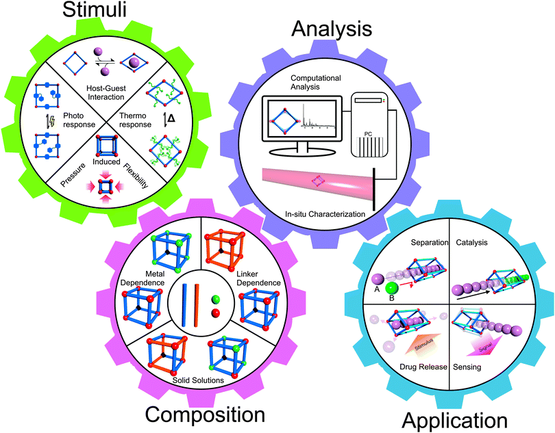
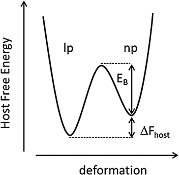
This definition of SPCs refers to reversible structural transformations of the type crystal-to-crystal or crystal-to-amorphous (or less crystalline), which are essentially phase transitions. So-called breathing MOFs, which feature a drastic change in unit cell volume (pore volume) upon external stimuli (e.g. guest molecule adsorption/desorption), are prominent examples of SPCs.7 These materials transform between open pore and closed pore (cp) or narrow pore (np) and large pore (lp) forms. The field has been pioneered by the groups of S. Kitagawa and G. Ferey and has been expanding since the first major conceptual article has appeared in 2004.8 However, among the about 20![[thin space (1/6-em)]](https://www.rsc.org/images/entities/char_2009.gif) 000 coordination network structures, which may be classified as MOFs and are listed in the Cambridge Structural Database (CSD), only less than 100 compounds reveal substantial breathing (np ↔ lp) transitions or related stimuli responsive properties. The progress has been reviewed continuously and we explicitly refer to these excellent previous articles.5–13 The latest article by D. M. Jenkins and co-authors refers to breathing MOFs based on categorizing breathing modes or mechanisms by the concept of dimensional rigidity, i.e. analyzing which part of the framework is (more) rigid and which part is (more) flexible.12 Herein, we will build upon these previous reviews and provide a collection of representative examples for discussion of the various modes of flexibility of MOFs, which are important for the progress of the field. Therefore, we will not restrict our definition of “flexibility” or “softness” to phase-transitions and breathing phenomena in a narrow sense, rather we will include some examples of dynamic features of MOFs, which are not connected with larger changes of the unit cell volume. Reviewing the recent literature published after the last comprehensive review in 2009,7 it was striking that there are numerous examples of MOF systems showing structural flexibility. However, only a few systematic studies are conducted, which mostly concentrate on MIL-53 (Materiaux Institute Lavoisier), MIL-88 or paddle-wheel based pillared-layered frameworks. In our review we will cover several flexible MOF systems beyond those, nonetheless, also focusing on the archetypal systems. Also we will include sections on in situ analysis, computational modeling and applications of flexible properties of MOFs (Fig. 1). The various forms of applications and conceptual visions around flexible MOFs viewed as soft porous crystals have been discussed in the perspective review by S. Kitagawa and co-workers.6
000 coordination network structures, which may be classified as MOFs and are listed in the Cambridge Structural Database (CSD), only less than 100 compounds reveal substantial breathing (np ↔ lp) transitions or related stimuli responsive properties. The progress has been reviewed continuously and we explicitly refer to these excellent previous articles.5–13 The latest article by D. M. Jenkins and co-authors refers to breathing MOFs based on categorizing breathing modes or mechanisms by the concept of dimensional rigidity, i.e. analyzing which part of the framework is (more) rigid and which part is (more) flexible.12 Herein, we will build upon these previous reviews and provide a collection of representative examples for discussion of the various modes of flexibility of MOFs, which are important for the progress of the field. Therefore, we will not restrict our definition of “flexibility” or “softness” to phase-transitions and breathing phenomena in a narrow sense, rather we will include some examples of dynamic features of MOFs, which are not connected with larger changes of the unit cell volume. Reviewing the recent literature published after the last comprehensive review in 2009,7 it was striking that there are numerous examples of MOF systems showing structural flexibility. However, only a few systematic studies are conducted, which mostly concentrate on MIL-53 (Materiaux Institute Lavoisier), MIL-88 or paddle-wheel based pillared-layered frameworks. In our review we will cover several flexible MOF systems beyond those, nonetheless, also focusing on the archetypal systems. Also we will include sections on in situ analysis, computational modeling and applications of flexible properties of MOFs (Fig. 1). The various forms of applications and conceptual visions around flexible MOFs viewed as soft porous crystals have been discussed in the perspective review by S. Kitagawa and co-workers.6
The advantages and potential application fields of flexible materials were recognized very early. For example, by exploiting the flexible properties of the human hair to absorb and release water from air with slight changes in its dimensions and weight, Leonardo da Vinci was able to build the first hygrometer. The diversity of envisioned applications of flexible MOFs is remarkable, however, most of the investigations performed up to now concern gas separation (pressure-swing adsorption) and sensor technology.14 For the adsorptive gas separation process, high capacity and highly selective adsorbents are key factors to realize the energy-efficient adsorption separation. In principle, flexible MOFs can combine these two requirements due to the general high adsorption capacity on one side, and the ideal selectivity in the pressure region, where one of the components can open the framework and the second one cannot, on the other side. Therefore, the challenge is to engineer a flexible MOF in a way that only specific interactions dominate the recognition and pore opening for a targeted adsorptive. Furthermore, for pressure swing adsorption, materials with small volume changes associated with gate opening (for example linker rotation caused adsorption) would be beneficial. For the application of MOFs as adsorbents for adsorptive gas storage, the so called working capacity is crucial. It is the difference in adsorption capacity at maximum storage pressure and the residual amount of gas at the lowest pressure allowed into the storage tank. Microporous MOFs show excellent overall uptake of gas, but quite low pressure (usually below 5, or even below 1 bar) should be applied to remove the gas from the MOF completely. The gate pressure MOFs with “gate closing pressure” in the right pressure region (above 1 bar) can help to overcome this problem. The vision is to go beyond host–guest interaction related stimuli, and expand the functional concept of framework responsiveness to factors causing the structural changes being dependent on general physical stimuli, such as light, mechanical deformation, thermal, electrical or magnetic stimuli. The reversible and controllable change of the materials density, dimensions, and optical, magnetic, and electrical properties is a requirement for using a flexible MOF as a sensor or a switching device. Combination of fundamental physical properties of stimuli responsive frameworks with host–guest interactions will create novel perspectives for unique functions. Eventually, the integration of such materials into a working system must be solved. The latter would greatly facilitate system integration in established technology fields, such as microsensors, micromechanical devices, and nanomedicine. For instance, using unique properties of selective adsorption, flexible MOFs could be used as catalytic nanoreactors, adsorbing exclusively educts from a mixture and then releasing the reaction products from the pores by applying an external stimulus. An enormous change in cell volume during adsorption could be used for the construction of micromechanical devices by transformation of volume expansion into mechanical energy.
2. General aspects of framework flexibility
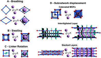
For a systematic discussion of flexible MOFs in the following chapters, we need to classify the different modes of framework flexibility. One widely accepted possible distinction of the different modes of flexibility was presented by Bousquet et al. and Coudert et al. (Fig. 2).15,16 Usually, framework flexibility is connected with supramolecular host–guest interactions. However, MOFs as soft porous crystals may show framework flexibility also in the absence of guests or without the involvement of adsorption and desorption phenomena. Flexibility or responsivity may be triggered by an external stimulus in general (by guests and external force fields, such as mechanical stress, temperature and interactions with light, etc.; furthermore electrical and magnetic interactions are predicted to be further possible stimuli).2.1. Breathing, swelling, linker rotation and subnetwork displacement
As breathing we want to entitle (reversible) transitions of metal–organic frameworks, during which the (substantial) displacement of atoms of the framework is accompanied by a change in unit cell volume (ΔV ≠ 0). Characteristic distances and angles of the unit cell change and the crystallographic space groups of the two distinct phases (np and lp) may be different. The prototypical example for this kind of flexibility is the MIL-53(M) family ([M(bdc)(OH)]n with bdc = 1,4-benzenedicarboxylate, and M = Al,17 Fe,18 Cr,19,20 Sc,21 Ga,22 In23). Because of the wide variety of structure forming metals and linker derivatives, the influence of different structure building units on the framework flexibility has been extensively studied from a theoretical and experimental point of view, with more than 400 publications published up to date.The swelling mode is characterized by a (gradual) enlargement of the MOF unit cell volume (ΔV ≠ 0) without a change in the unit cell shape and typically without a change in the space group.
The most representative material possessing the swelling mode of flexibility is MIL-88.24 The crystal structure is based on a trimeric M3O(H2O)2X6+ (M = Fe3+, Cr3+; X = F−, OH−) SBU (Secondary Building Unit) that consists of three truncated tetrahedra that are interconnected by dicarboxylic acids: fumaric acid (MIL-88A), bdc (MIL-88B), 2,6-ndc (2,6-naphthalenedicarboxylate; MIL-88C) or bpdc (4,4′-biphenyldicarboxylate; MIL-88D).25 The changes in the unit cell parameters and cell volume are found to be strongly guest dependent. Thus, starting from the evacuated structure (423 K) of MIL-88A, the volume of the unit cell increases from 1135 Å3 to 1840 Å3 in the case of n-butanol adsorption, to 1970 Å3 after adsorption of ethanol, to 2090 Å3 for the methanol filled material, and to 2110 Å3 after soaking in water.24
A flexibility mode which is also related to swelling is thermal expansion or shrinking in the absence of guest molecules (or not triggered by guest adsorption/desorption), which is found for some of the most archetypal “rigid” MOFs, e.g. MOF-5 (also known as IRMOF-1; [Zn4O(bdc)3]n)26 or HKUST-1 (Hong Kong University of Science and Technology; [Cu3(btc)2]n btc = 1,3,5-benzenetricarboxylate).27 The phenomenon of thermal expansion of such MOFs will not be the focus of this article.
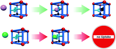
Linker rotation is defined as a (continuous) transition where the spatial alignment of a linker is changed by turning around a rotational axis. A simple prototype of this flexibility mode is ZIF-8 (Zeolitic Imidazolate Framework, [Zn(mIm)2]n, mIm = 2-methylimidazole).28 The inconsistence of the crystallographically determined pore windows size with the adsorption properties of the material forced the MOF community to explain this phenomenon. The combined experimental and theoretical studies have led to the conclusion that the rotational linker movement causes the expansion of the pore windows and the adsorption of molecules larger than expected.29,30 Framework flexibility based on linker rotation can be used to engineer special functions. One interesting example was presented by Seo et al. The framework [Cd2(pzdc)2(BHE-bpb)]n (pzdc = 2,3-pyrazinedicarboxylate; BHE-bpb = 2,5-bis(2-hydroxyethoxy)-1,4-bis(4-pyridyl)benzene) consists of [Cd2(pzdc)2]n layers interconnected by alkyloxy functionalized pyridyl linkers.31 At the end of the alkyloxy side chains of the pyridyl pillars an OH group is situated, which can interact with the OH groups of neighboring pyridyl pillars. These interactions lead to a gating of the pore, which triggers selectivity in adsorption of certain guest molecules. If polar molecules approach the gate, they can interact with the metal center. This leads to a rotation of the pillar, which eventually ends up in the opening of the pore space (Fig. 3).
Subnetwork displacement is a phenomenon restricted to systems having individual frameworks, which are not connected to each other by (strong) chemical bonds, but interact only by rather weak forces (van der Waals interactions) and thus the subnets can drift, relocate, or shift in regard to each other. This includes interpenetrated three dimensional (3D) frameworks, as well as interdigitated and stacked two dimensional (2D) frameworks.8,32–34 For instance, the 2D MOF [Cu(dhbc)2(bipy)] (Hdhbc = 2,5-dihydroxybenzoic acid, 4,4′-bipy = 4,4′-bipyridine) shows a gate-opening/closing after a certain threshold pressure of nitrogen, oxygen or methane is applied.35 Interpenetration has been considered for a long time as a drawback in the design of porous materials. There have been many strategies developed to avoid catenation to achieve ultra large pore spaces e.g. the use of topologies that cannot interpenetrate (e.g.rht),36 bulky side chains37,38 or template addition.39 However, the adsorption of small molecules (e.g. H2) can benefit from interpenetration. By confining the pore space, the number of adsorption sites increases and also the specific matching of the cavity of the MOF to the target molecule can increase.40,41
Within the concept of taking advantage of softness and flexibility, the interest connected with catenation and interdigitation is the possibility of inducing sorption selectivity (guest recognition) by guest selective, induced subnetwork movements. An outstanding example of the usefulness of catenation for sorption selectivity was given by Maji et al.32 with a pillared-layer framework consisting of two dimensional [Ni(bpe)2]n (bpe = 1,2-bis(4-pyridyl)ethane) sheets, which are connected by dicyanamide pillars (N(CN)2−). The as-synthesized (as) onefold interpenetrated framework has the composition [(Ni(bpe)2(N(CN2)))(N(CN2))(H2O)5]n, accommodating water, as well as N(CN)2− anions. The two interpenetrated nets are positioned in such a way that there are two different types of channels. One small channel (2.81 × 0.61 Å2), incorporating the N(CN)2− anions and one large channel (6.50 × 4.74 Å2), incorporating the water. After activation at elevated temperatures, the water is removed, yielding [Ni(bpe)2(N(CN2))][(N(CN2))]n, which retains the pore structure of the as form with only small changes. The permanently porous framework can undergo a subnetwork shifting transition by exchange of N(CN)2− with N3−. A second interesting example was given by Yang et al.42 The MOF [(Me2NH2)1.75[In(BTPC)]1.75]n (NOTT-202a; University of NOTTingham) based on the tetratopic linker biphenyl-3,3′,5,5′-tetra(phenyl-4-carboxylate) (BTPC) is interpenetrated and consists of two crystallographically independent nets (A and B). Net A has binodal diamondoid topology. In contrast to net A, net B is composed of two disordered equally occupied nets (B1 and B2) that are interwoven into each other. The overall structure can be viewed as a partially interpenetrated framework with the ratio of two nets, A and B, of 1![[thin space (1/6-em)]](https://www.rsc.org/images/entities/char_2009.gif) :
:![[thin space (1/6-em)]](https://www.rsc.org/images/entities/char_2009.gif) 0.75.
0.75.
This compound is highly flexible, but so far it is not clarified if the flexibility arises from subnetwork mobility or transitions within the respective independent frameworks.
2.2. Photoresponsivity
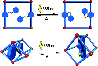
If organic molecules, which change their conformation or structure upon interaction with light, known as photoswitches, are implemented into MOFs, the pore size and shape, and hence the ability to adsorb certain guests, can be controlled by light irradiation. The most common way to introduce photoswitches is their addition as a functional side group to the linker. Even though there is a wide range of different photoswitchable molecules, only the prototypical azobenzene group has been incorporated into MOFs so far. In most cases the azobenzene photoswitch dangles into the pore and after light exposure (365 nm) changes its conformation from trans to cis. This is usually accompanied by a change in the accessibility of the pore space. The switch to the initial state can be triggered by either absorption of light of a higher wavelength (i.e. 440 nm) or by heating (Fig. 4). An example of a photoswitchable linker was first given by Modrow et al.43 In their work, an azobenzene functionalized bipyridine derivative was used in the synthesis of the pillared-layer based framework [Zn2(2,6-ndc)2(azo-bipy)]n (azo-bipy = 3-azo-phenyl-4,4′-bipyridine). Exposure of the material to light of a wavelength of 365 nm triggers the transition of the linker from the thermodynamically stable trans to the cis isomer. A reversible switching back can be achieved by either irradiation with light of a wavelength of 440 nm or by thermal treatment. This concept was pursued by other groups and further exploited. Brown et al.44 were able to prepare an azobenzene functionalized linker that can be introduced into IRMOF-74-III [Mg2(C26H16O6N2)]n. By switching from the trans-conformer to the cis-conformer, the pore aperture expands from 8.3 Å to 10.3 Å. Also the light-induced release of adsorbed dye was demonstrated by controlling the conformation of the azobenzene with the appropriate wavelength of light. Park et al. prepared an IRMOF-1 derivative containing azobenzene functionalized bdc-type linker.45 Notably, when the azobenzene is in the cis-conformation, the material has a substantially lower CO2 uptake in comparison to the material containing the linker in the trans-conformation.A different approach was undertaken by Yanai and coworkers.46 In their work the [Zn2(bdc)2(dabco)]n (dabco = 1,4-diazabicyclo[2.2.2]octane) framework was loaded with azobenzene photoswitches as guest molecules. The [Zn2(bdc)2(dabco)]n framework is known to perform slight changes in the crystal structure upon exposure to different solvents.47 Interestingly, the [Zn2(bdc)2(dabco)]n framework is also able to mimic the behavior of the photoswitch. When the azobenzene is present in the cis form, the MOF is contracted around the azobenzene guest. After exposure to light, the conformation of the guest is changed to the trans isomer and the framework expands to the lp form. Photoresponsive MOFs are still very scarce.
The third approach to incorporate photoswitchable behavior into a MOF is to use flexible linkers that undergo a reversible conformational change upon light exposure. Although the implementation of photoswitchable backbones into metal–organic frameworks could be achieved, light induced flexibility of the framework could be observed only in one case.
Lyndon et al.48 prepared a triply interpenetrated pillared layered framework built up from an azobenzene containing pillar and a stilbene containing linker with the formula [Zn2(AzDC)2(4,4′-bpe)]n (AzDC = azobenzene-4,4′-dicarboxylate; 4,4′-bpe = trans-1,2-bis(4-pyridyl)ethylene). The light-induced conversions between the two isomeric forms of the framework were confirmed by adsorption measurements: the structure changes are reflected in the large variation of CO2 uptake. The transition between the cis and trans isomer is very rapid and local – no structure of the lp phase that triggers the CO2 release could be determined.
2.3. Thermoresponsivity
Thermoresponsive MOFs are all those MOFs that show a reversible change in their lattice parameters after exposure to a temperature program without alteration of the molecular composition. Thus, materials that contain solvent guests are excluded from this class, since exposure to elevated temperature in this case would only lead to a phase transition induced by guest desorption. In this context we need to distinguish between two phenomena. Based on the structure at room temperature, (i) systems that after activation are present in their large pore form and (ii) systems that are contracted and possess narrow pores after activation. Systems in group (i) are most likely to undergo a phase transition when cooled and systems from group (ii) undergo a reversible phase transition when heated. Negative or positive thermal expansion (NTE or PTE, respectively) is a phenomenon that describes the expansion or shrinkage of a framework before a complete phase transition occurs. In other words, NTE and PTE are continuous processes.Some representative materials, which show PTE or NTE, and respectively changes in their unit cell parameters during the heating/cooling from room temperature until the threshold temperature of the phase transition is reached, are listed in Table 1. A common method to compare PTE and NTE of materials is to compare their thermal expansion coefficients α.
| MOF | Axis | α (MK−1) | Ref. |
|---|---|---|---|
| Cd(im)2 | a, b | + 92.6, −22.5 | 51 |
| MOF-5 | a | −16 | 52 |
| HKUST-1 | a | −7.5 | 53 |
| Ag(mIm) | a, b, c | +130, +44, −24.5 | 54 |
| HMOF-1 | a, b, c | +177, −21, +2.1 | 55 |
| FMOF-1 | a, c | +230, −170 | 56 |
| [Zn2(BME-bdc)2(dabco)]n | a, b | −380, +1161 | 57 |
| [Ni(H2diol)(DMF)2]n | a, c | +16, +323 | 58 |
| [Zn(NIY-bc)(OH)]n | a, b, c | −21, −21, +127 | 59 |
| Ag3[Co(CN)6] | a, b | +150, −130 | 60 |
| Cd(CN)2 | a | 20.4 | 61 |
| Zn(CN)2 | a | 16.9 | 61 |
A prominent example is the well studied MIL-53 system. Upon cooling down in vacuo to low temperatures a lp → np phase transition is observed at approximately 125 K.49 A large hysteresis (volume vs. T) is observed and the material transforms gradually back to the lp form above 325 K and the phase transition is finished at approximately 375 K. Theoretical calculations lead to the assumption that this behavior is caused by a decrease of the benzene rings motion. Their fast rotation is believed to help span the diamond shaped channels of MIL-53(Al). Walker et al.50 took a closer look at the origins of the thermally induced flexibility of MIL-53(Al) and found that dispersive interactions stabilize the np at low temperatures. At increased temperatures the higher entropy of the rotating linker molecules leads to the formation of the lp phase.
Another example of a material that shows a np → lp transformation is a functionalized analogue of the [Zn2(bdc)2(dabco)]n62 system, namely [Zn2(BME-bdc)2(dabco)]n (BME-bdc = 2,5-bis(2-methoxyethoxy)benzenedicarboxylate).57
The pores of this material are filled with dangling side chains that can interact with each other (Fig. 5A). In the as-synthesized state, the pores additionally accommodate solvent molecules and the material is present in the lp form. Upon activation, contraction to the np form occurs. When the temperature is increased, the thermal movement of the linkers' side chains is increased (and hence the side chains require more space) inducing the pore swelling and phase transition to the lp form at 493 K. Interestingly, the temperature for this phase transition is highly dependent on the type of linker functionalization (fu-bdc = functionalized benzene-1,4-dicarboxylate) in a series of [Zn2(fu-bdc)2(dabco)]n. When the BME-bdc linker is exchanged by the analogue DB-bdc (2,5-dibutoxybenzenedicarboxylate), a much lower transition temperature is observed (120 K). However, if this linker is used, the phase transition is not fully reversible. By preparing solid solutions containing both mentioned linkers, the transition temperature is tunable over a considerable range. Similar observations were made by Grobler et al.59 for a zinc(II) containing MOF of the composition [Zn(NIY-bc)(OH)]n. The used asymmetric (1H-naphtho[2,3-d]imidazol-1-yl)benzoate (NIY-bc) linker has a rotational degree of freedom along its bridging axis (Fig. 5B). When heated until a certain threshold temperature, the rotation is so strong that the pores open in order to avoid energetically non-beneficial collision of naphthalene groups from neighboring NIY-bc molecules.
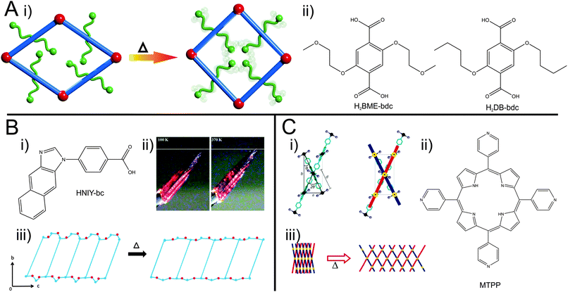 | ||
| Fig. 5 (A) –(i) Schematic illustration of the pore re-opening of [Zn2(BME-bdc)2−x(DB-bdc)x(dabco)]n upon exposure to heat; (ii) functionalized bdc-type linkers H2BME-bdc and H2DB-bdc; (B) – (i) linker used in the synthesis of [Zn(NIY-bc)(OH)]n. (ii) Photograph of a single crystal of the compound at different temperatures (100 K left and 370 K right); (iii) depiction of the phase transition occurring in the framework. (C) – (i) Schematic representation of the hinge in HMOF; (ii) illustration of the porphyrin linker (MTPP) incorporated into HMOF. (iii) Representation of the “lattice-fence-like” expansion of HMOF upon heating. (Reprinted with permission.55,57,59 Copyright 2013. American Chemical Society.) | ||
A further example of a MOF featuring a phase transition upon heating was shown by DeVries et al.55 The framework called HMOF (Hinged Metal–Organic Framework; Fig. 5C) was prepared from CdI2 and a meso-tetra(4-pyridyl)porphine linker (MTPP). Each cadmium ion possesses an octahedral coordination sphere, with 4 pyridyl groups of different porphine linkers coordinating to the Cd in the equatorial position and two iodines coordinating in the axial position. Two of the equatorially coordinating porphines contribute to the formation of a 2D sheet. The other two porphines belong to the second grid, skewed to the initial grid. This leads to a lattice-fence like topology, where parallel grids are linked by grids skewed to them. In this arrangement, the axially coordinating iodine ions of adjacent grids are in close proximity to each other. By heating, the iodines' thermal movement increases and neighbouring iodine molecules start to repulse each other, leading to a swinging out of the lattice fence-like structure. The common motif of these examples of guest independent thermal responsiveness is most likely entropy based motions of the linkers. If dangling (and flexible) side groups are pinned to the backbone of the linkers, the effect of their motions is transduced to the framework.
Thermal amorphization is another phenomenon observed for some materials. Bennett et al.63 presented a series of ZIF like materials that undergo an amorphization after heating to 300 °C. Interestingly, when the material is heated to 450 °C the formation of a new, dense, high temperature phase is observed. The amorphous phase and the high temperature phase are recoverable to room temperature.
2.4. Mechanical properties, elasticity
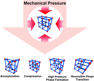
The mechanical property of MOFs, their “softness”, is associated with a highly anisotropic elastic behavior of the materials. This property is fundamental to all the above mentioned stimuli dependent phenomena, which are related to structural flexibility. Cheetham and co-workers pioneered the investigation of the mechanical properties of dense and porous coordination network compounds and metal–organic frameworks.64 Various phenomena, like pressure induced amorphization65,66 or phase transitions to a new high pressure phase,67 inaccessible by conventional synthetic methods, have been reported. However, these types of structural transformations are not necessarily reversible, while compressions are in any case considered to be fully reversible after the pressure has changed back to the initial conditions.68–70 Interestingly, some MOFs not only show stress induced reversible deformations, but undergo a complete phase transition, giving rise to an additional stimulus triggering flexibility. ZIF-8 is an interesting example in this context (Fig. 6). Chapman et al.66 showed that the framework is compressed rapidly by 5% when a pressure of 0.34 GPa is applied (under hydrostatic and non-hydrostatic conditions). When the pressure is further increased, an irreversible phase transition to an amorphous state is observed, however, N2 adsorption shows that this state is still highly porous. Moggach et al.67 performed in situ single X-ray diffraction on ZIF-8 with increasing pressure (under hydrostatic conditions with EtOH/MeOH as a pressure transducer). The authors show, that the unit cell volume increases first (4900.5 Å3 → 4999.6 Å3) up to a pressure of 0.18 GPa. From that point the unit cell volume decreases until a pressure of 0.96 GPa, and the volume of the unit cell reaches a value similar to the initial one (4893.5 Å3). From this pressure, the cell volume increases again, and a phase transition to a new high pressure-phase occurs at 1.47 GPa. The obtained high pressure-phase of ZIF-8 regains the initial status at a pressure of 0.82 GPa during pressure reduction. It is reasoned that the twisting and reorientation of the linker are responsible for the observed phase transition. Gagnon et al.70 analyzed the behavior of a zinc phosphonate framework [Zn(BB-pc)·2H2O]n (ZAG-4) (Zinc-Alkyl Gate; BB-pc = 1,4-butanebis(phosphonic acid)) under increasing pressure (hydrostatic conditions, EtOH–MeOH mixture). In this case a steady reduction of the unit cell volume to 27% was observed, while increasing the pressure up to 7.32 bar. Interestingly, all cell parameters shrink until a pressure of 1.65 GPa is reached. From this point on, the length of the b-axis slightly increases, while a and c continue to decrease. After reaching ambient pressures again, the structure goes back to the initial state. The reason for this behavior is attributed to a drastic decrease of the O–Zn–O angle and the distance between the Zn atoms in the SBU.An example of pressure induced linear elastic phenomena in MOFs is negative linear compressibility (NLC).71 When a sample is exposed to pressure, usually a compression along all three unit cell axis is expected. However, in some cases the shrinkage is anisotropic and while two cell parameters decrease, the third one might increase. This anisotropic behavior upon compression is labeled as NLC. Since there are only a few examples from the world of metal–organic frameworks, we will not further stress this nonetheless very interesting example. Yot et al.72 showed that MIL-47(V(IV)) [V(O)(bdc)]n (the V containing analogue of MIL-53) which is classified as a rigid material, undergoes a phase transition from the activated lp phase to the np phase when a certain mechanical pressure is applied. The mechanochemical behavior of this material was surveyed using Hg porosimetry and high pressure X-ray diffraction. In the intrusion curve three distinct regions are observed, which can be explained as follows. At the start of the measurement, the material is present in the known lp phase and the powder is compressed into the penetrometer (below 2 MPa), afterwards the interparticle volume is filled with Hg (2–3.5 MPa).
Interestingly, at 85 MPa the authors observe an increase of intruded Hg, which they correlate to a switch from the lp to the np, since they assume that the pore size of MIL-47(V) is too narrow to let the Hg penetrate. In this case, mercury only acts as a pressure transducer. To confirm these findings, high pressure PXRD (powder X-ray diffraction) measurements with silicone oil as a pressure transducer were performed, which fit well to the assumptions made from the porosimetry measurements. Similar experiments on MIL-53(Cr) also show pressure induced phase transitions.73
2.5. Nanoscale and memory effects
Downsizing MOF crystallites to the mesoscale regime can alter the gas adsorption properties (kinetics as well as overall uptake).74–78 However, there have been only a few studies involving nanosized flexible MOFs. For example, the X-ray diffraction patterns of nanosized crystals of the flexible framework CID-1 [Zn(ip)(bipy)]n; ip = isophthalate; (CID = Coordination Polymer with Interdigitated Structure) reveal different interlayer distances as compared to the macrocrystalline state.77 In a follow up study, Hijikata et al. had a deeper insight into the differences in framework dynamics and crystal structure between CID-1 and NCID-1 (Nano CID-1; crystal size: 50 nm × 320 nm). The methanol sorption isotherm already indicates a difference between these two structures: in the NCID-1 no hysteresis is observed contrary to the bulk sample. Activated guest-free CID-1 shows a cp, but certain guests trigger a reorientation of the linkers and guests can be adsorbed in the framework.From the X-ray patterns of the nanosized analogue, a slightly distorted activated cp state is observed upon activation, leading to a different packing of the 2D layers. Additionally, NMR measurements showed that the rotation of the aromatic rings of the bipy show a much higher velocity in NCID-1. Hence, this structural and dynamical difference of NCID-1 leads to increased sorption kinetics and the disappearance of the sorption hysteresis.
Sakata et al.76 prepared nanosized samples of the catenated [Cu2(bdc)2(bipy)]n. The [Cu2(bipy)2]n 2D layers are bridged by bipy linkers. When the MOF is solvated, the layers are stacked on top of each other and the bipyridine molecules orthogonally connect them. After drying, the layers are shifted to each other and the bipy is tilted (see Fig. 7). This turning of the pillars and shifting of the layers is accompanied by a displacement of the interpenetrated frameworks in regard to each other. Thus, a lp form in the solvated state can be distinguished from a np form in the dried state. Interestingly, when the MOF crystallites are downscaled to a particle size below 60 nm, the material does not undergo a phase transition to the np anymore after drying. Instead, the material keeps the shape of the solvated form until the material is exposed to temperatures of 473 K. This leads to a material that has different sorption isotherms, determined by its thermal treatment history.
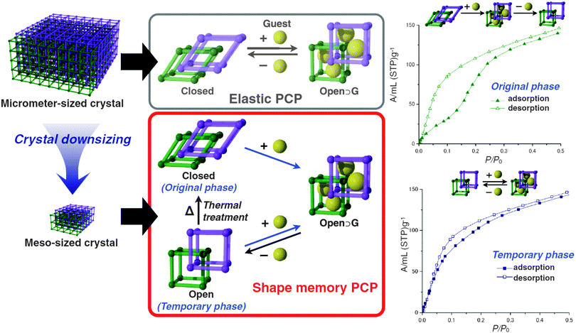 | ||
| Fig. 7 Schematic depiction of the flexible behaviour of micro-sized [Cu2(bdc)2(bipy)]n in comparison with meso-sized [Cu2(bdc)2(bipy)]n. Right – methanol adsorption isotherms of the closed (original phase) and the open (temporary phase) of meso-sized [Cu2(bdc)2(bipy)]n. (Reprinted with permission.76 Copyright 2013. American Association for the Advancement of Science.) | ||
2.6. Deposition on substrates and integration into thin films
The integration of flexible MOFs into thin films or devices has not yet been studied very intensively.79 There are only rare examples of the deposition of flexible metal–organic frameworks as thin films on suitable substrates. Most likely, the modes of flexibility, which do not involve a change in unit cell dimensions (and pore volume) will not be influenced by surface deposition of MOF crystallites. However, it can be anticipated that the surface anchoring of swelling or breathing MOFs might influence the structural phenomenon. One early example was given by Scherb et al.,80 who deposited thin films of MIL-88B on SAM (Self Assembled Monolayer) functionalized gold surfaces. The SAM triggers an oriented growth of the samples along the [001] axis, this means the hexagonal channels grow parallel to the surface. The sample was loaded with DMF after synthesis, left to dry in air for 24 hours and the diffraction pattern was measured in regular intervals. Interestingly, a shift of the (002) reflection to smaller 2Θ angles is observed during the desorption process, indicating an elongation of the distances between the diffracting centers along this cell axis (along the hexagonal channels).3. Flexibility and the metal node
The most fascinating flexibility mode is the “breathing”. It is a cooperative effect of both, the inorganic node and organic ligand. Up to now, there has been no comprehensive theory established, that provides predicting and full understanding of the key flexibility parameters of MOFs. Although, based on the existing experimental data, G. Ferey and C. Serre have formulated empirical rules that should be satisfied simultaneously to allow the structure to breath.7 Some of them also concern metal clusters: The inorganic brick should have a mirror plane with the carboxylates ordered in symmetrical positions around it. Another rule concerns the ratio of C/M ≥ 2 (C: number of carbon atoms of the carboxylic groups surrounding the cluster; M: number of metallic atoms within the cluster). We restrict our discussion to the most relevant examples, the metal nodes of MIL-53, MIL-88, and paddle-wheel based MOFs.3.1. Deformation at the MIL-53 node
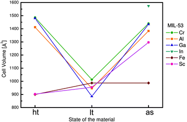
Within the MIL-53(M) series (Table 2), the chromium version MIL-53(Cr) is one of the most studied flexible MOFs. It is made of a [Cr(OH)(COO2)2]n chain-like SBU and benzenedicarboxylate as a linker.19,20 Directly after the synthesis, the solid is isolated in the MIL-53as form containing terephthalate molecules and solvent in the pores. After evacuation at 300 °C the large pore MIL-53ht phase is obtained, which after cooling under ambient conditions transforms to the np MIL-53lt phase due to adsorption of water molecules. By considering bdc as a rigid linker, the flexibility of the solid can be explained mainly by changes in the inorganic node or dihedral angle between SBU and the linker. On the one hand, detailed analysis of the MIL-53(Cr) structure shows no significant changes of the SBU that could result in a drastic volume change from 1012.6 Å3 in the MIL-53(Cr)lt to 1486.3 Å3 in the MIL-53(Cr)ht (Fig. 9).The O–Cr–O angles are in all three forms in the range of 88–94°. The Cr–O–Cr angle also does not change dramatically, being in the range of 125–132°. On the other hand, the change in the dihedral angle between O–Cr–Cr–O and the O–C–O planes (177.5° for -as, 180° for -ht and 139° for -lt forms) is indicative of the breathing effect of the framework. The structural transformation upon water adsorption is explained by weak intermolecular interactions between the framework's polar groups and water molecules. Another evidence for the synergetic effect of the inorganic node and the linker during the breathing behavior of MIL-53 is the rigid behavior of DUT-481 (Dresden University of Technology) and MIL-69 ([M(OH)(2,6-ndc)]n; M = Al, Cr),82 which are isoreticular to MIL-53 and contain 2,6-ndc as a linker. Both compounds are rigid, whereas MIL-69 is present in the np form and DUT-4 in the lp form. An interconversion between these two forms does not take place. DUT-5 has also the same inorganic building unit, but H2bpdc as a ligand. This material is also rigid with permanent porosity.81 The MIL-47(V) structure (also isostructural to MIL-53) is constructed by 1D chains of V4+O6 octahedra, interconnected by bdc. The only difference is in the valence of the metal atom that suggests the presence of the protonated μ2-OH group in the case of MIL-53 series and the μ2-O group in the case of MIL-47(V). The latter does not show a breathing effect during the adsorption of polar molecules.83 Leclerc et al. were able to prepare a second form of MIL-47(V) which contains bridging OH groups and V(III) metal centers. This material shows again flexible behavior upon sorption of polar guests.84 From Fig. 8 and Table 2 it is evident that the flexibility of MIL-53 frameworks depends on the metal node. Outstanding examples are the indium, scandium and the iron containing MIL-53 frameworks. For MIL-53(In) no activated phase has been published yet. The iron and scandium analogues show a pore contraction upon activation contrary to the other MIL-53 frameworks. While the remaining materials show an increase in cell volume upon activation (lp), the iron and scandium frameworks are in their guest free state even more contracted (cp) than the np form. The Cr, Al, and Ga show all similar lp → np transitions when the ht material is exposed to ambient conditions and adsorbs H2O. In summary, the above mentioned examples show that breathing in MIL-53 materials is a completely cooperative effect of metal node and the linker molecule.
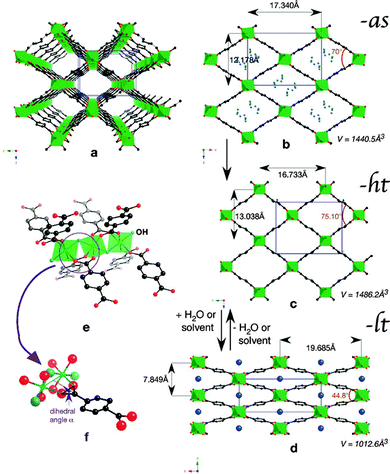 | ||
| Fig. 9 (a) Perspective view of MIL-53-ht; (b)–(d) Projection along the direction of the channels of: (b) MIL-53-as (with some atoms of the disordered terephthalic acid in blue), (c) MIL-53-ht, and (d) MIL-53-lt with variable parameters; (e), (f) Perspective views of the connection between the chromium chains and the terephthalate ions. Chromium octahedra are depicted in green, water molecules in dark blue, OH groups in pale blue, oxygen in red, and carbon in black. (Reprinted with permission.7 Copyright 2009 Royal Society of Chemistry.) | ||
3.2. Deformation at the MIL-88 node
MOFs containing trivalent metal ions often feature the trigonal prismatic SBU M3O(COO)6(H2O)2X (M = Fe, Cr, Al; X = F−, OH−). While hydrothermal synthesis under acidic conditions (HF) yields rigid mesoporous MIL-10085 and MIL-10186 frameworks, the utilization of trimeric iron(III) acetate as a metal source and fumaric, terephthalic, 2,6-naphtalenedicarboxylic (2,6-ndc) or 4,4-biphenyldicarboxylic acid (bpdc) as a ligand under basic conditions leads to the formation of flexible solids, namely MIL-88A, MIL-88B, MIL-88C and MIL-88D, respectively.24,25,87 As synthesized structures of the MIL-88 family show swelling flexibility upon solvent removal, as well as upon adsorption of polar solvent molecules (Fig. 10). By hydrating the evacuated form of MIL-88A, the cell volume increases by 85% from the np (1135 Å3) to the lp form of MIL-88-H2O (2110 Å3). The channels contract by activation and can be re-opened when exposed to polar solvent molecules. The driving force is the formation of hydrogen bonds between solvent molecules and the framework.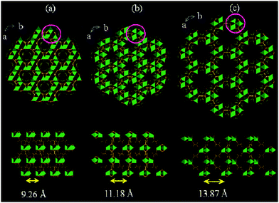 | ||
| Fig. 10 Simulated crystal structures of the MIL-88A framework in its np (a), as (b), and lp (c) forms. (Reprinted with permission.87 Copyright 2005 American Chemical Society.) | ||
Although the geometry and connectivity of the SBU itself do not change significantly, the cluster exhibits continuous rotation of the trimers around the [001] direction by a maximum of 30° during the transformation. It became possible due to the knee-cap-like rotational axis, located on the O–O axis of the carboxylate functions, around which the trimer and the phenyl rings can change their respective angular orientations (Fig. 11).
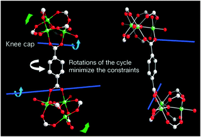 | ||
| Fig. 11 Depiction of the hinge in MIL-88 around which the rotation that induces the pore swelling occurs. (Reprinted with permission.133 Copyright 2007 American Association for the Advancement of Science.) | ||
3.3. Deformation at the paddle-wheel node
A paddle-wheel or so called “soft SBU”88 serves as an inorganic brick for most of the known flexible MOFs (Fig. 12).31,89–97 It consists of a metal dimer interconnected by four carboxylic groups and represents a four-connecting (square or pseudo-square) SBU. Connection of the paddle-wheels by linear linkers results in [M2L2]n planar grids that are usually interconnected in the third direction by pillar ligands (e.g. dabco, bipy, etc.) forming a 3-D framework with α-Po topology.The most representative example of such a system is the MOF [Zn2(bdc)2(dabco)]n (Fig. 12).98 The planar grid is built by [Zn2(COO)4] paddle-wheels and bdc linkers. In the axial positions, the paddle-wheels are interconnected by dabco forming the 3D network. The crystal structure of the as-synthesized phase shows a strong mutual distortion of [Zn2(bdc)2] grids in the c direction (Fig. 12). Interestingly, the evacuated structure shows ordering of the latter. The contraction of the crystal structure is provoked by adsorption of benzene molecules and is in a good correlation with the adsorption stress model of Neimark.99 In contrast to MIL-53, where the SBU is not actively involved in the breathing process, in [Zn2(bdc)2(dabco)]n deformation of the paddle-wheel plays a key role in the transformation. Thus, the O–Zn–O adjacent angle in the paddle-wheel changes from 90° in the lp structure to 87° in the np phase after benzene adsorption. At the same time the “knee-cap” O–Zn–Zn–O and O–C–O dihedral angle, responsible for the breathing of MIL-53, changes from 0° in the evacuated lp structure to 9.8° in the np one. The same structural transition from the as-synthesized np to the evacuated lp phase was observed in the case of the isomorphic compound [Co2(bdc)2(dabco)]n.92 In contrast, the X-ray powder diffraction patterns of as-synthesized and evacuated [Cu2(bdc)2(dabco)]n match well indicating the immutability of the framework structures.89 By expansion of the framework using longer 2,6-ndc instead of bdc in the synthesis, the DUT-8 ([M2(2,6-ndc)2(dabco)]n) family with Cu(II), Zn(II), Co(II) and Ni(II) as metal nodes was obtained.95,96 Similarly to [Cu2(bdc)2dabco]n, DUT-8(Cu) shows rigid behavior with no structural changes upon solvent removal. The DUT-8 frameworks, based on Ni, Zn, and Co paddle-wheels, indicate structural changes during the evacuation. In the case of DUT-8(Zn), the changes are irreversible underlining the influence of the metal node. In accordance with nitrogen adsorption isotherms, supported by X-ray powder diffraction patterns it was established that the DUT-8(Ni) structure closes and opens completely showing a unique, and extremely large reversible breathing transition. The flexibility of the Co analogue is less pronounced.
The paddle-wheel related flexibility was also demonstrated by Kitagawa et al. on the example of the twofold interpenetrated framework [Zn2(bdc)2(DF-bpb)]n (DF-bpb = 2,3-difluoro-1,4-bis(4-pyridyl)benzene).88 During activation, the reversible structural transformation of the paddle-wheel was monitored by single crystal XRD. The structural evolution from 2a to 2d (Fig. 13) sequentially shows the contraction of the structure. In the crystal structure of 2a, the paddle-wheel M–M dimer and the pyridyl based pillar lie on the same axis. In the intermediate structures 2b and 2c the pyridyl ligand is tilted, thus decreasing the interlayer distance. Simultaneously, a distortion of the square planar coordination of the bdc linkers around the paddle-wheel is surveyed.
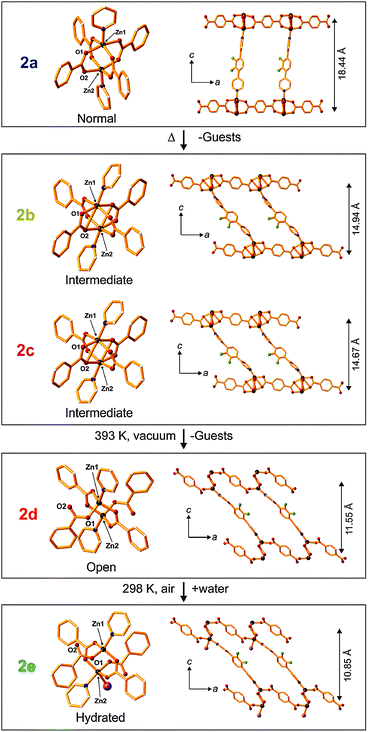 | ||
| Fig. 13 Crystal structure of [Zn2(bdc)2(DF-bpb)]n in the forms 2a–2d showing structural transformations upon desolvation and water coordination. Color code: Zn – gray; F– green; N – blue; O – red,; H2O – violet (in 2e). Non-coordinated guest molecules and hydrogen atoms are omitted for clarity. Left: coordination environments of the zinc cluster; Right: views of the single framework along the b-axis. (Reprinted with permission from ref. 88. Copyright 2011 American Chemical Society.) | ||
Finally, the structure of 2d shows partial decomposition of the paddle-wheel with the change in the coordination geometry of Zn from square-pyramidal to tetrahedral.
A similar effect was observed by Rosseinsky et al. during dehydration of a Zn paddle-wheel based MOF [Zn2(TBAPy)(H2O)2]n containing a tetratopic ligand (TBAPy = 1,3,6,8-tetrakis(p-benzoic acid)pyrene).100 As a result of water removal, the framework dimensionality changes from 2D to 3D inducing changes in magnetic and optical properties.
Thus, one can conclude that the paddle-wheel contributes considerably to the flexibility of the framework, but the impact is strongly dependent on the nature of metal used in the synthesis. The Cu based compounds are usually more rigid in comparison to the Zn, Ni and Co analogue.
A more complex type of SBU, however still related to the paddle-wheel structural motif, was observed in [Zn2(BPnDC)2(bipy)]n (BPnDC = benzophenonedicarboxylate), which is a twofold interpenetrated flexible framework also known as SNU-9 (Seoul National University).101 Later, the intrinsic structural dynamics of SNU-9 were investigated in situ during the adsorption of CO2 and N2 by Kaskel and co-workers.102 The structure consists of unusual asymmetric paddle-wheel SBUs (Fig. 14), composed of two Zn atoms coordinated by four carboxylic groups from BPnDC linkers and two nitrogen atoms from bipy molecules in the axial positions.
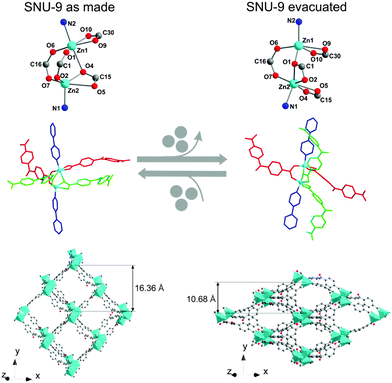 | ||
| Fig. 14 Crystal structure of SNU-9: as synthesized (left) and SNU-9 activated (right). Top: geometry of the SBU. Middle: ligand arrangement around the SBUs (molecular color code: bipy in blue; crystallographically independent benzophenonedicarboxylate molecules in red and light green). Bottom: view of a single framework along the [101] direction. (Reprinted with permission.102 Copyright 2014. American Chemical Society.) | ||
Two Zn atoms and bipy molecules are not linearly arranged, as usual for paddle-wheel pillar-layered frameworks. During the activation, a Zn–O bond rearrangement occurs.
Such rearrangement leads to the contraction of the structure in the [010] direction accompanied by decrease in unit cell volume from 10![[thin space (1/6-em)]](https://www.rsc.org/images/entities/char_2009.gif) 182 Å3 to 7334 Å3, and accessible void volume from 40.8% to 12.8%. Interestingly, the adsorption of CO2 at 195 K and N2 at 77 K proceeds in a different way: the formation of an intermediate phase during the CO2 adsorption could be postulated, while the transformation from np form to the lp structure occurs quasi in one step by nitrogen physisorption. The gas loaded compounds have also different final crystal structures at relative pressures around p/p0 = 0.9, depending on the guest molecule. According to the powder diffraction data, the structure of N2@SNU-9 is identical to the structure of the as synthesized compound. The cell volume of CO2@SNU-9 is slightly higher.
182 Å3 to 7334 Å3, and accessible void volume from 40.8% to 12.8%. Interestingly, the adsorption of CO2 at 195 K and N2 at 77 K proceeds in a different way: the formation of an intermediate phase during the CO2 adsorption could be postulated, while the transformation from np form to the lp structure occurs quasi in one step by nitrogen physisorption. The gas loaded compounds have also different final crystal structures at relative pressures around p/p0 = 0.9, depending on the guest molecule. According to the powder diffraction data, the structure of N2@SNU-9 is identical to the structure of the as synthesized compound. The cell volume of CO2@SNU-9 is slightly higher.
4. Flexibility and functionalized linkers
A systematic discussion on the various types of framework flexibility based on the motions of the linkers, rather than primarily focusing on the coordination geometry at the metal nodes, was given by Murdock et al. in their review article entitled “Approaches for synthesizing breathing MOFs by exploiting dimensional rigidity”, as we already highlighted in the introduction.12The categorizing principle was based on conformational properties of the linkers and on the dimensionality of the (cooperative) motions of the framework. The authors analyze twisting, bending, and tilting modes of rigid and (partly) flexible linkers. We refer to this recent article as we want to avoid repeating its content herein. Rather, our focus will be on the opportunities of tailoring framework flexibility by the substituent effects at the linker. i.e. by introducing functional groups. An early example for implementing dangling substituents at the backbone of the linker being not involved in framework constructions is the prototypical IRMOF-series introduced by Eddaoudi et al.103 In this, the bdc linker is replaced by analogues containing simple substituents on their benzene core, e.g. Br- or NH2-groups (IRMOF-2 and IRMOF-3, respectively). These functionalities point into the pore and influence the pore shape and metrics, as well as the polarization noticeable. It was shown that by smart linker functionalization the properties, such as sorption selectivity can be tuned in such kind of structurally rigid MOFs. Moreover, the same concept of linker functionalization can be applied to tailor flexibility together with functionality and even to trigger flexibility in otherwise much less flexible or even rigid MOFs.
Several methods have been established in order to introduce functionalities into MOFs. The most straight-forward way is the incorporation of functionalized linkers during conventional solvothermal synthesis.104–113
However, this is not always possible, e.g. due to steric demand or due to additional ligating groups leading to a different framework topology. This can be avoided by introduction of the functional groups after the MOF synthesis. One method to achieve this is postsynthetic modification (PSM), during which a simple functional group (e.g. –OH, –NH2 or N3) is further reacted under mild reaction conditions (e.g. esterification, click reaction).114–126 For some functionalities it is also possible to protect them with an easily cleavable group (“protection group”) before MOF synthesis and set them free after synthesis.37,38,127,128 Postsynthetic exchange129,130 (PSE, also known as solvent assisted ligand exchange, SALE131–134), a rather new but very powerful method, has also proven to be extremely useful for the introduction of functionalities into a MOF that otherwise would not be possible.135 When using this method, the MOF is exposed to a highly concentrated solution of a linker molecule at elevated temperatures and the linkers of the MOF exchange with the targeted linker molecules. In the following, we would like to discuss the influence of functional groups on the flexibility of metal–organic frameworks.
4.1. Functionalized bdc-type linkers
Comprehensive studies have been conducted on the functional groups influence on the breathing transitions in MIL-53(Al) and MIL-53(Fe). For the MIL-53(Al) framework the plain bdc linker was substituted with –Cl, –Br, –CH3, –NO2, or –(OH)2 functionalized bdc derivatives.136Fig. 16 shows the evolution of the cell parameters in these frameworks from the as-synthesized to the lp and to the np phase (and to a DMF infiltrated phase). The cell volumes for the as-synthesized phases of the MIL-53(Al) derivatives cover a range between 1375 and 1450 Å3 representing the lp structure. The largest values for the as-synthesized cell volume are observed for rather bulky groups that do not enable hydrogen bond formation with the solvent molecules (–Cl, –Br, –CH3 and –NO2). Smaller cell volumes are observed for groups that can interact via hydrogen bonding with the solvent molecules used during synthesis (–NH2, –(OH)2, or –(COOH)2). In these cases, a tighter (energetically more efficient) packing of the solvent and excess linker molecules within the cell is expected. When the pores are filled with DMF, it is observed that the MOF containing the bulkiest non-polar groups has the highest cell volume with the sequence MIL-53(Al)-Br > MIL-53(Al)-CH3 > MIL-53(Al)-Cl. For the MOFs containing polar side groups, the cell volume of the DMF filled form decreases with decreasing steric demand of these groups (MIL-53(Al)-NO2 > MIL-53(Al)-(OH)2 > MIL-53(Al)-NH2). When the material is activated, a guest free high temperature (ht) phase is obtained, which possesses in all cases a lp structure. The only exception is MIL-53(Al)-(OH)2, which collapses upon complete removal of all guest molecules.The differences in the breathing behavior of the MIL-53(Al) derivatives can be attributed to different intra-framework and host-framework H-bonding properties of the material. The μ2-OH groups and their interactions with guest molecules have been identified as one of the key features during the breathing transitions in MIL-53.
By implementing into the MOFs some functional groups (which to some extent can be considered as guest species), the electronic properties of the μ2-OH groups get modulated. These side groups may interact directly with the μ2-OH groups.
Devic et al.137 have performed a very extensive study on the influence of –Cl, –Br, –CH3, –NH2, –(OH)2, –(COOH)2 and –(CF3)2 functional groups on the flexibility and frameworks' dimensions of MIL-53(Fe) during solvation using a range of different solvents such as H2O, ethanol (EtOH), pyridine (py), and tetrachlorethane (C2H2Cl4). Interestingly, the differences are more pronounced than for the aluminium analogue. It is notably that MIL-53(Fe) shows a different chronology in its phase transitions. The as-synthesized MIL-53(Fe) material has a lp form and is filled with guest molecules (excess linker and solvent). After activation and removal of the incorporated guests, the material is unlike the Cr and Al analogue not in a lp phase, but contracts even more than the comparable narrow pore forms, giving rise to the closed pored form (cp). Interestingly, the degree of contraction of the cp is highly dependent on the nature of the functional group attached to the bdc linker and the resulting specific guest–framework interactions (Fig. 15). For the non-functionalized framework and the (OH)2-bdc containing framework the dry ht form has a pore more narrow than the respective hydrated lt np phase (V = 917 and 900 Å3, respectively). All the other materials show a ht phase that has dimensions similar to the lt phase. It is worth mentioning that MIL-53(Fe)-(CF3)2 already has a high cell volume of around 1318 Å3 in the dried ht phase. This can be attributed to (i) the bulkiness of the side group or (ii) to the inability of the perfluorated side chains to yield any H-bonding interactions with the μ2-OH groups and (iii) to the repulsion of CF3 groups of adjacent bdc linkers. This conclusion is underlined by the behavior of the MIL-53(Fe)-(COOH)2 framework, which has a bulky functional group attached, but a much lower cell volume (1079 Å3), indicating a strong interaction between the COOH groups with the bridging μ2-OH. This interaction seems to be so strong that none of the solvents, which are used for exposure, leads to an opening of the pore. When exposed to water, all materials – except the –(OH)2 functionalized analogue – show similar lattice parameters as the lt (np) phase (which has water from air adsorbed in the pore space). Like for MIL-53(Al)-(OH)2 a huge increase in the cell volume is observed when water is offered to the framework. This is reasoned by the polar backbone and by the good ability of the water molecules to form hydrogen bonds with the linkers' OH groups and the polar backbone. Exposing the series of frameworks to ethanol leads to a further expansion up to the maximum cell volume observed in this study for most compounds (except MIL-53(Fe)-(CF3)2, which has the highest cell volume when pyridine is infiltrated).
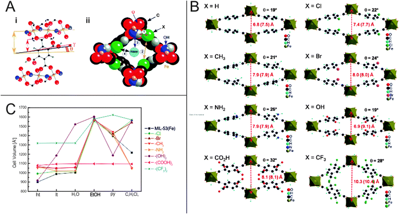 | ||
| Fig. 15 (A) (i) – Depiction of the O–O rotational axis in MIL-53(Fe), which triggers the phase transition; (ii) – Different interaction sites in the pore of MIL-53(Fe). (B) Calculated crystal structures of differently functionalized MIL-53(Fe)(ht) analogues. Red numbers indicate the length of the b-axis, numbers in brackets give the length of the b-axis in the hydrated form. (C) Evolution of the unit cell volumes depending on the state of the material. (Reprinted with permission.137 Copyright 2010 American Chemical Society.) | ||
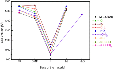 | ||
| Fig. 16 Evolution of the cell volume in MIL-53(Al) materials depending on the treatment of the material. | ||
Henke et al. prepared a series of dialkoxy functionalized linkers and applied them in the synthesis of a series of dabco pillared layered materials of the general formula [Zn2(fu-bdc)2(dabco)]n (where fu-bdc is functionalized bdc, see Fig. 17 for a listing of the used linker molecules).138 Depending on the chain length, polarity, and grade of saturation of the added alkoxy chains, the scope of flexibility of the material can be adjusted. Similar to flexible MIL-53 materials, also a rotation around the O–O axis of the carboxylate occurs leading to an increase or decrease of the cell volume. All as synthesized materials are present in the lp, when the materials are activated, a contraction to the np form is observed. This is due to the interaction of the side chains bound to the framework's backbone. When the solvent is removed, the side chains interact strongly, leading to a complete contraction of the framework. The magnitude of this contraction is strongly dependent on the nature of the substituents. If the side chain is too long, no contraction is observed (e.g. fu-bdc = DPe-bdc), since (i) already in the lp form beneficial interactions between adjacent side chains can occur or (ii) the chains fill the pore volume and restrict the space necessary for contraction. When the chain length is decreased, a strong contraction is observed for DB-bdc and BME-bdc containing pillared-layered MOFs. Even though the polarity of the materials is different (with BME-bdc containing a oxygen molecule in the fourth position of the side chain), only a slight difference in the pore contraction is observed (for 2,5-BME-bdc – 15%; for DB-bdc – 14%). The difference is more noticeable for side chains with a different grade of saturation. While the framework, built up from DP-bdc linkers possessing completely saturated side chains, contracts by 20% (the respective isomer [Zn2(DiP-bdc)2(dabco)]n contracts by 21%), the related framework containing unsaturated propynyloxy side chains [Zn2(BIPY-bdc)2(dabco)]n contracts by 28%.
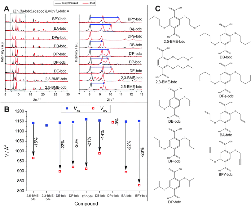 | ||
| Fig. 17 (A) Powder patterns of as-synthesized (black) and dried (red) [Zn2(fu-bdc)2(dabco)]n. (B) Evolution of the cell paramters during the transitions from the as-synthesized lp to the dried np of the framework. (C) Listing of the linkers that were used to prepare the discussed pillared-layered frameworks. (Reprinted with permission.138 Copyright 2012. American Chemical Society.) | ||
Cohen and coworkers selected the same parent system for modulation of the flexible properties by applying the concept of post synthetic modification of [Zn2(NH2-bdc)2(dabco)]n. Reaction of the NH2 group with carboxylic acid anhydrates of different chain lengths, alters the degree of flexibility of the frameworks. However, this has been so far the only systematic study which focuses on the employment of PSM to trigger and tune flexibility of a MOF.139
Apart from the frameworks undergoing breathing transitions, also very interesting studies were conducted on the swelling MIL-88B framework. Horcajada et al. exchanged the bdc linkers with a wide variety of different functionalized bdc linkers.140 A big influence of the type and number of functional groups on the pore swelling of the material was observed. The general trends of the experiments are displayed in Fig. 18. The volume of the unit cell of non-hydrated np material is strongly dependent on the type of functionality – the higher the steric bulk of the group, the higher the necessary volume to accommodate the functional groups. It is interesting to see, that by judicious choice of substituent, the material's surface area can be tuned. If monosubstituted linkers are used (Cl-bdc, Br-bdc, NH2-bdc, NO2-bdc or (OH)2-bdc), the pores are contracted and no significant BET surface area can be determined. If the linker, however, is double or quadruple substituted with sterically more demanding linkers (e.g. F4-bdc, (CH3)2-bdc, (CH3)4-bdc, and (CF3)2-bdc), the permanent porosity can be confirmed by nitrogen adsorption experiments.
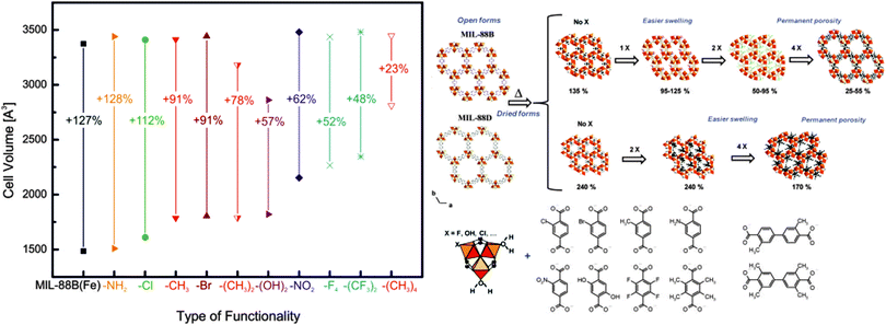 | ||
| Fig. 18 Left: depiction of the evolution of the cell volumes during the swelling process depending on the functionalities added at the bdc benzene core of MIL-88B(Fe) Right: schematic depiction of the pore swelling in MIL-88B and MIL-88D depending on the number of substituents on the benzene rings. (Reprinted with permission.140 Copyright 2011. American Chemical Society.) | ||
So far, there only have been few comprehensive studies that were able to compare differently functionalized MOFs. The flexibility of many systems is however very complex (metal and linker influence) and a generalization of how a certain group –X changes the responsiveness of a MOF to an outer stimuli is according to the literature not possible up to now.
4.2. Elongated linear carboxylate linkers
In two studies Dau et al. showed the influence of differently functionalized 4,4′-biphenyldicarboxylic acids on the sorption properties of bipyridine and dabco pillared layered Zn2+ frameworks.141,142 In their first study they prepared 2-phenylpyridine-5,4′-dicarboxylic acid and applied it in the synthesis of different MOFs. Interestingly, for the prepared pillared-layered frameworks distinct differences in the gas-adsorption isotherms were observed compared to the unfunctionalized bpdc, originating most probably from the differences in the framework dynamics upon adsorption. In a second study, nitro and dinitro-functionalized bpdc derivatives were prepared and employed in the synthesis of dabco and bipy pillared layered MOFs. Interestingly, the 2-NO2-bpdc forms a non-interpenetrated pillared layered framework for both cases, while the 2,2′-(NO2)2-bpdc linker forms the interpenetrated framework for the bipy pillared version and a 2D-coordination polymer in the case of the dabco pillar. The functionalized linkers have a distinct effect on the sorption properties of the materials. The observed hysteresis in the CO2-sorption isotherms suggests a dynamic framework behavior.5. Multivariate flexibility, solid solution MOFs of mixed linkers and metal ions
The integration of different building blocks, which feature the same coordination geometry (structure) and connectivity, can lead to the construction of mixed component MOFs (MIXMOFs),143–146 sometimes also referred to as multivariate MOFs (MTV-MOFs)147,148 or solid solution MOFs.149,150 In these single-phased materials at least two types of different metals (a) or differently functionalized linkers (b) are present. However, these different components are not regularly ordered, but rather random or inhomogeneous incorporation occurs. The concept of MIXMOFs (illustrated schematically in Fig. 19) can lead to advanced materials with complex functionalities, unusual and specific properties. Conceptually, by variation of the building block ratios in the synthesis batch, it is possible to control the composition and the resulting pore metrics and pore functionalities, offering a powerful approach to tailor and adjust the desired physicochemical properties of porous materials. Complexity and combinatorial richness can be introduced, far beyond the limitations of the single-component compounds.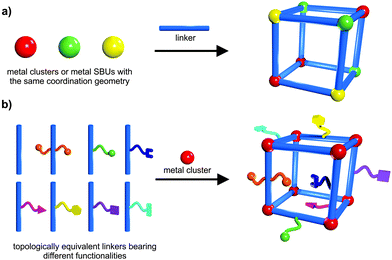 | ||
| Fig. 19 Schematic depiction of the construction of: (a) solid solutions of mixed metal ions; (b) mixed linkers leading to multivariate flexibility of MOFs. | ||
Regarding flexible MOFs, the construction of mixed-component systems is not extensively studied yet and to the best of our knowledge, there are only a few examples of tailoring the breathing behavior in mixed component MOFs. We want to address the most prominent ones in the following. Starting with flexible mixed-metal MOFs, the attention was mainly focused on the MIL-53 system. All MIL-53(M(III)) derivatives feature a np structure in their hydrated form. Upon heating, the frameworks start to “breathe” and transform, depending on the metal, either to a lp form (e.g. M = Cr) or to a cp form (e.g. M = Fe). Serre and coworkers thus investigated the influence of mixing cations featuring this antagonist flexibility.151 The prepared solid solution (evaluated metal contents: Cr: 60%, Fe: 40%) shows a structural behavior being completely different from both of the parent compounds, since it initially contracts to a cp form at 343 K and re-expands to a lp form upon further heating to 463 K. This two-step behavior of contracting and expansion is neither observed in MIL-53(Cr), nor in MIL-53(Fe) and clearly indicates the formation of a single phased solid-solution. Structural differences are also observed from the sorption measurements (Fig. 20). The CO2 triggered phase transitions in MIL-53(Cr0.6Fe0.4) [Cr0.6Fe0.4(OH)(bdc)]n (cp → np → lp, indicated by the stepwise uptake and in situ PXRD studies) are distinctly different from the transitions observed for the parent frameworks, as well as from the theoretical calculations, indicating the pronounced effect of the mixed Cr–Fe chains in the network on the structural flexibility. Particularly, the facility of opening a pore might thus be tunable by controlling the Cr/Fe ratio.
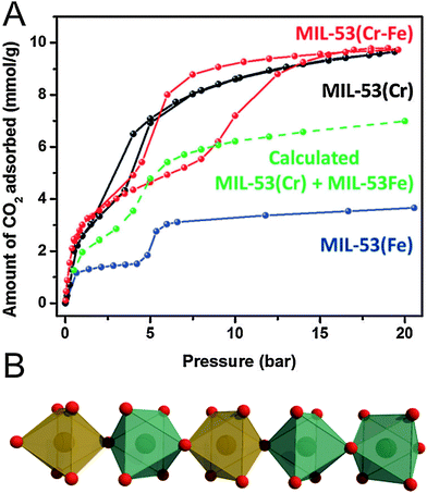 | ||
| Fig. 20 (A) Comparison of the CO2 adsorption isotherms of MIL-53(Fe–Cr), MIL-53(Fe), and MIL-53(Cr). (B) One dimensional SBU chains in MIL-53(Fe–Cr). Green and orange polyhedra represent iron and chromium SBUs, respectively. Red spheres represent oxygen atoms. (Reprinted with permission.151 Copyright 2012. The Royal Society of Chemistry.) | ||
Another example describes the formation of solid solutions by doping MIL-53(Al) with vanadium ions, conducted by Fischer and co-workers.152 The pure guest-free V-analogue of MIL-53 (called (MIL-47(V)) slightly differs in structure, as the metal centers are bridged by μ-O2− instead of μ-OH− groups, which is related to the higher oxidation state of the V(IV) ions. Notably, MIL-53(Al) features a flexible structure (guest and heat induced oscillation between lp and np phase), while the V(IV) analogue is rigid, due to the absence of the bridging μ-OH groups. And indeed, incorporation of different amounts of V confirms the expected trend: With increasing molar ratio of vanadium, a gradual change from a highly flexible framework structure to a completely rigid one is observed. 87% of vanadium is enough to suppress the structural transformation from the initial lp form to the np form upon CO2 adsorption. Accordingly, the guest pressure required for a subsequent np to lp transition decreases from 600 mbar to lower values with increasing vanadium content, until it completely disappears (for 87% VIV). Generally, the flexibility is thus strongly dependent on the VIV content in mixed Al/V chains. Worth mentioning, these two examples show that combination of either two flexible MOFs (Cr/Fe), or also of a flexible and a rigid one (Al/V) can lead to flexible solid solutions, which feature a breathing behavior completely different from the parent frameworks and which can be tuned over the whole range of metal ratios.
Besides the mixed-metal MOFs, there are also examples of flexible mixed-linker systems, which will be discussed in the following. Farrusseng and coworkers prepared a series of MIL-53(Al) derivatives containing different mixtures of bdc and NH2-bdc.153 They observed that the guest dependent behavior is highly influenced by the molar ratios of the applied linkers in [Al(OH)(bdc)1−x(NH2-bdc)x]n (with x = 0, 0.1, 0.2, 0.5, 0.6 and 1). All samples show a distinct two-step adsorption profile in the CO2 isotherms, attributable to the lp → np and np → lp form transformation at low and high pressures, respectively. The threshold pressure of the second phase transitions (np → lp) increases (from 665 kPa to 1770 kPa) with increasing NH2-bdc content. This indicates a more pronounced stabilization of the np form in the presence of a high NH2-bdc content, due to a larger number of stabilizing hydrogen bonds within the pore. Temperature-dependent PXRD studies reveal a np → lp transition at 60 °C (dehydration) for pure lt [Al(OH)bdc]n, which is not observed for pure lt [Al(OH)NH2-bdc]n. The phase transition temperature at intermediate NH2-bdc contents is spread over a temperature range and np and lp form can coexist in some cases. Evidently, with increasing amount of NH2-bdc, much higher temperatures are required for a full np → lp conversion.
The breathing behavior was also fine-tuned in pillared-layered [Zn2(BME-bdc)2x(DB-bdc)2−2xdabco]n (x = 0.25, 0.50, 0.75) solid solutions.138 Henke et al. showed that all frameworks feature a distinct lp → np contraction upon solvent removal and the scope of contraction is linearly enhanced with increasing amounts of BME-bdc. Notably, the CO2 pressure required to trigger the np → lp and the width of hysteresis also depends on the BME-bdc/DB ratio, however, non-linearly. [Zn2(BME-bdc)0.5(DB-bdc)1.5dabco]n shows a much higher transition pressure than pure [Zn2(DB-bdc)2dabco]n. Similar results were obtained for the thermoresponsive pore opening in a related study.57 The threshold temperature highly depends on the BME-bdc:DB-bdc ratio, but again non-linearly, since the phase transition of [Zn2(BME-bdc)1.5(DB-bdc)0.5dabco]n occurs at higher temperatures than the phase transition of pure [Zn2(BMB-bdc)2dabco]n, observed in DSC curves and also confirmed by variable temperature PXRD and differential scanning calorimetry (DSC) (Fig. 21).
Concluding, as seen from the above discussed examples, structural adaptivity in solid solutions (guest-dependent or temperature-dependent) can linearly be adjusted, however, non-linear effects are also possible and offer further tuning possibilities of the breathing behavior.
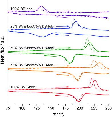 | ||
| Fig. 21 DSC curves of [Zn2(BME-bdc)2x(DB-bdc)2−2xdabco]n solid solutions. (Reprinted with permission.57 Copyright 2013 John Wiley and Sons) and Sons. | ||
6. In situ characterization and computational analysis
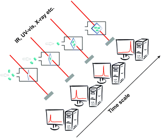
The investigations of dynamic structural changes in flexible MOFs require special in situ analytical techniques. The application of ex situ solid state characterization methods is often not sufficient to understand all the processes occurring in a system. In particular by a multi-step adsorption behavior of MOFs, the probability of the existence of intermediate states and coexistence of several states in a narrow pressure range is high. However, if a gas is used as a trigger molecule, only the starting state (empty framework) can be characterized by “ex situ” diffraction and spectroscopic techniques. To gain insight into the structural changes during the gas adsorption, the intermediate state should be stabilized for the time of measurement (in situ) and high time resolution during the adsorption process is beneficial (Fig. 22). Due to the crystallinity of MOFs, X-ray diffraction methods are predestinated for structure monitoring during the adsorption. Also in situ spectroscopic methods, such as NMR (Nuclear Magnetic Resonance), IR (Infra Red), RAMAN, EXAFS (Extended X-ray Adsorption Fine Structure) etc. are extremely useful, especially if the intermediate state is not crystalline or if motions of the framework need to be monitored, which do not correspond to crystallographic changes, such as linker rotations.6.1. X-ray diffraction methods
The structural transition in flexible MOFs is usually accompanied by enormous changes in the lattice parameters and cell volume. These microscopic changes often lead to macroscopic damage of the single crystals, which makes it often very difficult to use single crystals for in situ investigations. However, in situ single crystal X-ray diffraction experiments are also possible in some particular cases. For example, the structural transformation of the two-fold interpenetrated [Zn2(bdc)2(DF-bpb)]n during the stepwise drying of the single crystal was investigated by Kitagawa et al.88 The coordination environment of the Zn-atoms changes from square-pyramidal in the lp structure to a distorted tetrahedral in the np form. Single crystals of the flexible [Sc2(bdc)3]n were investigated in situ with different loadings of CO2, H2, CH4 and C2H6 by Filinchuk co-workers154 The details of framework rearrangements as well as the adsorption mechanisms of the above mentioned gases could be investigated. Moreover, well-defined adsorption sites for CO2, CH4, and C2H6 were determined.The thermally induced structural changes in [Cu2(OH)(SO3H-ip)(H2O)·2H2O]n (Cu-SIP-3; SO3H-ip = sulphoisophthalate) were also studied by in situ single crystal X-ray diffraction at variable temperatures.155 X-ray diffraction data were collected over a temperature range from 150 K to 500 K. Refinements of the data collected in the temperature range 150–365 K yielded the structure of hydrated Cu-SIP-3 (Fig. 23). In the temperature range of 370–405 K, no Bragg reflections were observed in the diffraction images indicating a loss of the long-range order in the crystal. A corresponding increase in the diffuse scattering from the crystal was observed. Obviously, a significant structural movement in this material is caused by water removal and is accompanied by increased movement of all atoms. Above 430 K, a highly crystalline, dehydrated material is formed (Cu-SIP-3), whose crystal structure could be determined. It has been shown that the structural transition can be fully reversed (under retention of the crystallinity) by exposure of the system to moisture.
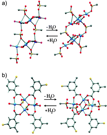 | ||
| Fig. 23 Structural transformations in Cu-SIP-3 during hydration/dehydration: (a) Chains of the copper tetramers in the low-temperature (left) and high-temperature (right) structures. (b) Copper tetramers in the low-temperature (left) and high-temperature (right) structures. Color codes: Blue balls – copper atoms; red balls – oxygen atoms; yellow balls – sulfur atoms; grey balls – carbon atoms (Reprinted with permission from.155 Copyright 2010. American Chemical Society.) | ||
Very recently, Kitagawa and coworkers were able to investigate the propagation mechanism of structural transformation in [Zn2(1,4-ndc)2(dabco)]n (1,4-ndc = 1,4-naphthalenedicarboxylate) through an entire single crystal for the first time.156 The contracted shell could be created on the outer surface of the single crystal by adsorption of organic molecules with dimensions, very close to the pore size of the framework. At the same time, the remaining part (the core) of the crystal stays in the original, open state. Using synchrotron grazing incidence single crystal diffraction measurements, the authors show that the structural transformation from the original phase to the deformed one is accompanied by sharing one out of four edges of the crystal cell to maintain the connectivity between the two phases. The obtained results clearly show that propagation of structural transformation and the domain formation is strongly correlated with the diffusion of molecules. Further development of this unique technique would definitely help to explain the mechanism of the structural transformation in other flexible MOFs.
For sensitive crystals, as well as for very small crystallites, powder X-ray diffraction is often the method of choice.157 In order to collect high quality powder X-ray diffraction data time resolved, high intensity synchrotron radiation is essential,42,157–160 but in principle, comparable experiments are also possible using the laboratory diffraction system. Often, the sample holder for in situ measurements is based on a thin-wall glass capillary (Fig. 24). The adsorption temperature is usually provided by a nitrogen cryostream setup that allows working in the temperature range of 80–500 K only.161,162 Such type of instrumentation was developed by the group of Llewellyn and implemented at the Swiss-Norvegian beamline (European Synchrotron Radiation Facility). The instrumentation was widely used for in situ investigation of MIL-53(M) (M = Al, Cr) materials using carbon dioxide and hydrocarbons as probe molecules.163–167 The main advantage of the capillary based setup is a possibility to perform in situ high-pressure gas adsorption experiments. For instance, pressures up to 100 bar can be achieved if the capillary with 0.5 mm inner diameter is used in the experiment.
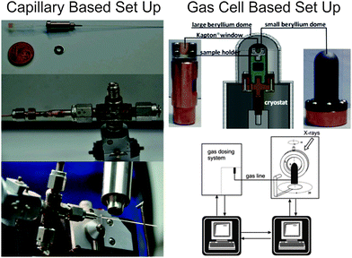 | ||
| Fig. 24 Capillary based experimental setup (left) (Reprinted with permission161) and gas cell, based on closed cycle He-cryostat (right) (Reprinted with permission.162 Copyright 2014. Elsevier.) | ||
To lower the possible working temperature up to 5.5 K and to achieve higher temperature stability, a system based on a closed cycle He cryostat and Be-dome (Fig. 24) was developed by Kaskel and co-workers.162 However, the use of a Be-dome constricts the operating pressure range to 1 bar only. The gas dosing can be performed in both cases manually or the conventional automated gas dosing system can be adopted for in situ measurements.
In recent years, in situ powder X-ray diffraction was widely used for the characterization of flexible MOFs. The in situ study of [Cu(bipy)2(OTf)2]n (OTf = trifluoromethanesulfonate), also known as ELM-12 (Elastic Layer Material), shows no significant structural changes after the first CO2 adsorption step in the isotherm, that agrees with a solvent accessible void of 17.9% for the activated structure. The second step in the isotherm is followed by a structural transition to the lp, leading to an increase of 38% of the unit cell volume.159 In case of CPL-1157 (Coordination Polymer with a Pillared-Layer Structure) with the composition [Cu2(pzdc)2(pyz)]n (pyz – pyrazine), the intermediate phase (ip) could be identified during the adsorption of acetylene at 270 K. The crystal structure of the ip form was solved from powder X-ray diffraction data, explaining the mechanism of acetylene adsorption on the framework. More than ten articles with regard to in situ XRD studies were published on MIL-53 materials.167–176 Combined in situ PXRD and Raman spectroscopy experiments were performed on the MIL-53(Cr) material using a CO2/CH4 gas mixture as adsorptive, confirming the preferable CO2 adsorption.167 In the same manner, the effect of ligand functionalization was investigated using CO2 high pressure adsorption. This proves the strong relationship between the functional group of the phenyl ring and flexible behavior of the framework. Surprisingly, –NH2 and –COOH functionalized MIL-53 materials show no structural transformation during the CO2 adsorption, in spite of the strong affinity of the adsorptive to these groups. Oppositely, materials containing –Cl, –Br and –CH3 functionalized bdc linkers show a flexible character.137 A successful combination of in situ PXRD with AIMD (Ab Initio Molecular Dynamics) simulation based approaches was used to explain the CO2 adsorption related breathing phenomena (in particular, the broadening of the reflections in the powder XRD of the close pored form) of MIL-53(Sc).170
The structural dynamics of the partially interpenetrated flexible indium based framework NOTT-202 was investigated by in situ PXRD studies using CO2 as the adsorptive. In this case, in situ powder diffraction data reveal the flexibility of the framework in the temperature and pressure range below the triple point of CO2.42
In order to investigate processes with fast kinetics, in situ EDXRD (Energy Dispersive X-Ray Diffraction) is the method of choice. Very intense white X-radiation allows to measure PXRD patterns of the sample within a few seconds. Thus, the adsorption process of liquid alcohols on hydrated MIL-53(Fe) was monitored by EDXRD.174 Also the adsorption kinetics for N/S-heterocycles on MIL-53(Fe) were studied by the same group using the same technique.171
Summarizing, the in situ powder XRD technique is mainly sensitive to structural changes of the host framework, although due to the physical limitations of X-rays, the method provides sometimes ambiguous information about the ordering of the adsorbed molecules, specifically in the case of light atom adsorbates. To solve this problem, in situ neutron diffraction can be used in some particular cases. By using deuterated adsorptives it is possible to determine the preferable adsorption sites. Mulder et al. studied the deuterium adsorption on MIL-53(Cr) by combined neutron diffraction and inelastic neutron scattering.175 It has been shown that the adsorption sites near the Cr–O clusters reach the highest occupations. Thus, in situ diffraction methods give significant information about structural changes of the framework and about preferable adsorption sites in the structure.
6.2. NMR-methods
The 129Xe NMR technique with thermally or hyperpolarized Xe as a probe has been widely used for characterization of porous solids, such as zeolites, amorphous silica–alumina, polymers, carbons, peptides, etc.177 In the recent few years, the method was also applied to study the interaction between the adsorbed Xe and flexible MOFs. 129Xe NMR spectroscopy of adsorbed xenon gives detailed information about the pore interior and dynamics, in particular the 129Xe chemical shift, line width, chemical shift anisotropy, and longitudinal relaxation time T1 are influenced by structural parameters, such as pore size, pore shape, composition of the pore walls, and dynamics.178 The MOF lattice itself and its changes during the adsorption of NMR active species can be studied. Since the changes in the framework are accompanied by the changes in pore size and/or their pore windows, flexibility can also be explored in an indirect way by using probes like 129Xe sensing the inner surface of the pores.Springuel-Huet et al. have performed in situ129Xe adsorption NMR experiments on the flexible MIL-53(Al) material at different temperatures and pressures.179 The authors use the chemical shift of Xe as an indicator of the local xenon amount and, consequently, of the extent of transformation from lp to np form. The hysteresis of the chemical shift variation versus xenon pressure observed for the signal corresponding to the lp form was explained by an exchange of the Xe atoms through the gas phase, between lp form and np form particles or by shrinkage of the one-dimensional pores at both ends of the crystal. The isothermal experiment (295 K) shows the adsorption of Xe on MIL-53(Al) even at low pressures confirming accessibility of the np form for the Xe atoms.
DUT-8(Ni) ([Ni2(2,6-ndc)2(dabco)]n) is a flexible gate-pressure material that was also studied using 129Xe NMR (Fig. 25).180 Isothermal in situ measurements at 237 K were performed in the pressure range from 1 to 19 bar and show only the signal of gaseous Xe within the pressure range from 1 to 12 bar. At 14 bar, a weak broad signal of adsorbed Xe at 227 ppm appears in the spectrum indicating the expansion of the structure. The desorption branch indicates both adsorbed and gaseous Xe in the whole pressure range from 14 to 1 bar, which is in good agreement with previously reported Xe adsorption data.96,181 The isobaric (15 bar) in situ study of DUT-8(Ni) in the temperature range from 237 to 292 K shows almost no adsorption by increasing the temperature to 270 K and higher, confirming the presence of the narrow pore form of the compound. Lower temperatures (at the same pressure corresponding to a higher p/p0) promote the gate opening, leading to the signal of adsorbed Xe at 225–230 ppm.
Recently, ZIF-8, which shows linker rotation, was explored using the same technique.181 Although the kinetic diameter of the Xe atom is much higher (4.4 Å) than the pore windows in the MOF structure (3.4 Å), the adsorption of Xe occurs due to the rotation of the linker. The study was performed at a constant pressure of 10 Torr in the temperature range of 138–323 K. Deriving from the signal position at ∼80 ppm, one can state that there is no specific interaction of Xe with the imidazolate moieties at ambient temperature. Low temperature spectra exhibit an abrupt increase in the chemical shift by more than 100 ppm within a narrow temperature range (between 163 K and 170 K). Thus, the chemical shift increases slowly when the temperature decreases from 380 K to 180–190 K, showing that the Xe–Xe interactions are negligible. After the transition that occurred at 166 K, the chemical shift remains constant and equal at around 215 ppm, which is typical for xenon dissolved in organic compounds and suggests that Xe atoms interact specifically with the imidazolate linkers, after the structural change, which occurs at low temperatures.
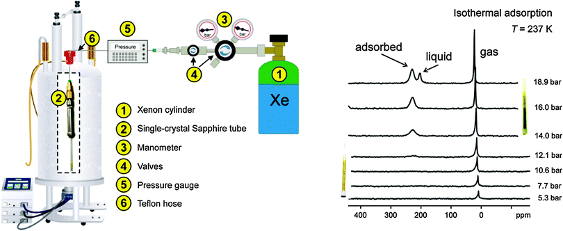 | ||
| Fig. 25 Schematic representation of an apparatus for high pressure in situ129Xe NMR experiments under variable thermodynamic conditions (left). In situ129Xe NMR spectra recorded during the adsorption and desorption of Xenon on DUT-8(Ni) at 237 K (right). (Reprinted with permission180 Copyright 2011. American Chemical Society.) | ||
In summary, in situ NMR is a powerful technique that can be used as a complementary tool to X-ray powder diffraction and provides particularly information about host–guest interactions in flexible MOFs. However, the use of this method is still limited, presumably because of the lack of accessibility of the instruments and restrictions on certain probe molecules. Only in situ NMR studies with Xe and 13CO2182 as a probe are described in the literature so far.
6.3. Raman/IR-spectroscopy
Vibrational methods are one of the most powerful techniques that provide information about chemical bonding, helping to determine the structure of investigated compounds. Under in situ conditions, these methods can provide information about both, structural changes of the host framework and its interaction with the guest molecules. Technically, both in situ IR- and Raman spectroscopic experiments were realized using microscopes, connected to the spectrometers. The detailed instrumentation setups are described by Weckhuysen et al.183 Usually Raman microscopes are installed at synchrotron beamlines, dedicated to in situ and operando investigations of catalysts.184 For example, in situ Raman spectroscopy was used by Kitagawa and co-workers to confirm the COO− bond rearrangements in the coordination environment of the Zn-based paddle-wheel unit in [Zn2(bdc)2(DF-bpb)]n.88 At 16 kPa CO2 pressure, the characteristic double band of νsym(COO−) vibration around 1425 cm−1 appears, along with the band from the adsorbed CO2 at 1374 cm−1 (Fig. 26). The peak change indicates that the cluster undergoes a bond rearrangement after the first step of CO2 adsorption at 195 K. Increasing pressure does not involve any further changes in the Raman spectrum apart from an increase in the intensity of the band related to adsorbed CO2.In situ IR spectroscopy during N2 adsorption at 100 K was used as one of the characterization methods in combination with UV-vis and powder XRD for investigation of the multi-step adsorption behavior in [Co(bdp)]n (bdp = 1,4-benzenedipyrazolate).185 It was confirmed that the C–N stretching vibrations for the pyrazolate rings have undergone transitions from np to intermediate phase 1 (ip1) and from ip1 to intermediate phase 2 (ip2) upon increasing the N2 pressure to 0.01 and 0.023 bar, respectively (Fig. 26).
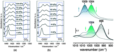 | ||
| Fig. 26 Left: Raman spectra of [Zn2(bdc)2(DF-bpb)]n upon (a) adsorption and (b) desorption of CO2 at 195 K (Reprinted with permission.88 Copyright 2011 American Chemical Society); right: overlayed in situ infrared spectra for the pyrazolate ring stretch vibrations in [Co(bdp)]n, recorded at 100 K with increasing N2 pressure up to 0.01 bar (bottom) and from 0.01 to 0.023 bar (top). These transitions are coincident with the phase transitions from the dry form (gray) to ip1 (green) to ip2 (blue) (Reprinted with permission.185 Copyright 2010. American Chemical Society.) | ||
In the case of adsorption of a CO2/CH4 mixture on MIL-53(Cr), in situ Raman spectroscopy was used to provide an estimation of the composition of the adsorbate phase, as well as of the lp/np ratio.167 For evaluating the lp/np ratio, the relative intensities of the characteristic bands at ∼1432 and 1444 cm−1 were used (νsym(COO) vibration). The band at 1432 cm−1 is characteristic for the np form, while the band at 1444 cm−1 carries the signature of the lp form. The corresponding Raman band intensities were integrated and compared with gravimetric adsorption measurements. It was concluded that only in the case of pure gases, the correlation between the two applied methods was good enough, while in the case of gas mixtures, Raman spectroscopy tends to overestimate the adsorbed amount of methane compared to the gravimetric measurements. Further, in situ IR spectroscopy was applied to study the host–guest interactions on MIL-53(Fe)–X (X = Cl, Br, CH3) solids upon adsorption of CO2.173 The experiments show the perturbation of the bands associated with the μ2-OH group. Both, the ν(OH) and δ(OH) bands are shifted (from 3649 cm−1 to 3621 cm−1, Δν(OH) = 28 cm−1 and from 842 cm−1 to 881 cm−1, Δδ(OH) = 39 cm−1) and the ν2 band of the adsorbed CO2 is split into two components (651 cm−1 and 661 cm−1). The shift of the ν(OH) and δ(OH) bands can be interpreted as a result of the formation of a hydrogen bond between the O atom of the CO2 molecule and the H atom of the μ2-OH group. Moreover, the information about μ2-OH⋯X (X – Cl, Br) intra-framework interactions can be extracted from δ(OH) band shifts.
Schröder and coworkers used in situ DRIFTS (Diffuse Reflectance Infrared Fourier Transform Spectroscopy) for monitoring the adsorption of SO2 on the partially interpenetrated flexible NOTT-202a framework.186 The overtone vibrations of SO2 were monitored in the region 2250–2540 cm−1. In the absence of the MOF, two overtone bands observed at ca. 2500 and 2350 cm−1 were assigned to overtone and combination bands, respectively. After the sample was introduced into the in situ cell, the new bands at 2461 and 2280 cm−1, consistent with adsorbed SO2 on porous material, appeared in the IR spectra (Fig. 27). Recently, in situ RAMAN spectroscopy was used to confirm chemisorption of CO molecules (81.7 K) on the open metal sites of the flexible MOF [Cu(aip)]n (aip = 5-azidoisophtalate).187 Pressure increase from 10 Pa to 1 kPa causes the appearance of the absorption band at 2168 cm−1, clearly confirming the formation of a Cu⋯CO module.
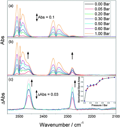 | ||
| Fig. 27 In situ DRIFTS spectra of gaseous SO2 at various pressures (0–1 bar) in the overtone region at 273 K: (a) KBr + SO2, (b) KBr + NOTT-202a + SO2, and (c) the difference spectra, showing the growth of two new bands. Arrows indicate the growth of bands due to adsorbed SO2 with increasing pressure. Inset: Plot showing the growth of new bands at 2461 (red ▲) and 2280 cm−1 (blue ■) as a function of SO2 pressure. The areas were averaged at each pressure to produce a point-to-point average (black beta-spline line) (Reprinted with permission. Copyright186 2013. American Chemical Society.) | ||
6.4. X-ray absorption spectroscopy
EXAFS (Extended X-ray Absorption Fine Structure) is a powerful technique for determining the local structure of the metal cluster, in particular if single crystal X-ray data are not accessible for any reason. The rather simple measurement principle, as well as the rapidity makes the method appropriate for in situ measurements. Moreover, usually both in situ powder XRD and EXAFS often can be measured quasi–simultaneously on the same sample under the same conditions.184 Currently, the method is widely used for in situ characterization of MOF materials during hydration and dehydration processes.188 For instance, the local bond rearrangement of the metal clusters of the rigid frameworks HKUST-1 and UiO-66 (Universitetet i Oslo, [Zr6(OH)4O4(bdc)6]n)189 upon dehydration was studied. It should be mentioned that the use of XAS (X-ray absorption) is still not widely developed to study the flexibility of MOFs. It could be particularly useful in the cases of changes in coordination geometry during the phase transition. For example, in situ EXAFS was used for activation process monitoring of the Co based flexible MOF [Co(Hoba)2·2H2O]n (Hoba = 4,4′-oxybis(benzoic acid)).190 On the one hand, the differences observed in the XANES region (X-ray Adsorption Near Edge Spectroscopy) before and after activation (Fig. 28) are indicative of the local coordination geometry changes at the cobalt sites upon removal of the water molecules. On the other hand, reduction of the degeneracy value of the Co–O scattering pair in the EXAFS fitting from 6 in the as-synthesized phase to 4.2 in the activated phase confirms the expected decrease in coordination number accompanied by nearly complete removal of coordinated water molecules. In some particular cases, peculiarly in the case of crystalline-to-amorphous structural transitions, XAS could be the only method that can provide information concerning changes in the local structure of the metal cluster. For instance, the structural changes in DUT-13 [Zn4O(BenzTB)3/2]n; BenzTB = N,N,N′,N′-benzidinetetrabenzoate) cannot be explained by using exclusively in situ powder XRD because of amorphization of the sample in a certain range of the isotherm.191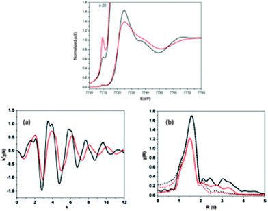 | ||
| Fig. 28 Top: cobalt K-edge XANES spectra of 1 (black) and 1′ (red) pre edge feature at 7709.5 eV shown with 20× magnification. Bottom: comparison between EXAFS spectra of 1 and 1′ in (a) k space and (b) FT R space (also includes the theoretical first shell fits); see text for details of fitting. (Reprinted with permission.190 Copyright 2012 American Chemical Society.) | ||
6.5. Theoretical description of structural transitions in flexible MOFs
However, a second condition for breathing is that ΔFhost should be small enough or ΔK must be large enough,192 in other words again, the energy gain due to the adsorption in the narrow pore structure (high K2) must compensate the energy penalty of the structural transition. If this narrow pore form is too narrow, the small pore volume V(2)p will not adsorb enough gas to compensate ΔFhost, only if K2 is high (for example for CO2), the transition will occur. Thus, a very subtle interplay between adsorptive interaction and structural bistability makes it difficult to predict novel breathing MOFs ab initio.
Valuable outcomes of the theoretical description are free energy differences ΔFhost extracted from adsorption data. In most of the guest induced transitions (physisorption) these energy differences fall into the 2–6 kJ mol−1 range, for example ΔFlp–np = 2.5 kJ mol−1 per unit cell for MIL-53(Al). However, comparing such values for different MOFs may be misleading, since the unit cell is an arbitrary choice for the thermodynamic description and normalization would be needed. The analysis of temperature dependence of the isotherms may be used to calculate enthalpic and entropic contributions. Thus, in the case of Xe adsorption at MIL-53(Al), ΔHlp–np and ΔSlp–np were estimated to be 15 kJ mol−1 and 74 J (mol K)−1.194 As a result, the transition free energy was estimated to vanish at a lower temperature boundary of T = 203 (±20) K and the np structure becomes more stable below that temperature. On the other hand, entropy driven at high temperature (>300 K) the lp-structure is more stable independent of the Xe pressure. A simple estimation of this upper boundary (Tmax), above which gas adsorption does not induce the lp → np phase transition, was given as kTmax ≈ ΔHads,lp.193
A full p-T phase diagram for Xe adsorption in MIL-53(Al) was derived from thermodynamic analysis revealing the regions in which phase transitions occur195 and the general applicability was demonstrated by extending the methodology to CH4 and CO2 adsorption in MIL-53(Al),193 clearly revealing that the host guest interactions are non-specific and mostly dominated by the differences in adsorption enthalpy of the different gases. Thus, the upper boundaries (Tmax and pmax) above which gas adsorption does not induce the lp → np phase transition are observed for CO2 molecules with the strongest host–guest interaction due to their quadrupole moments. The larger stability domain of the np phase during CO2 adsorption in amino functionalized MIL-53(Al) was attributed to the increased affinity for CO2 due to the presence of amino groups.195
Overall, this phenomenological model is very general and applicable to many cases. The model can be extended for the prediction of structural transitions upon adsorption of gas mixtures, based on experimental pure component adsorption isotherms OFAST (Osmotic Framework Adsorbed Solution Theory), relying on Ideal Adsorbed Solution Theory (IAST) for prediction of co-adsorption and Langmuir fits of the experimental isotherms.196–198 A restriction may be the limited availability of adsorption data to obtain a good Langmuir fit for both phases or at least for the open phase for “gating” MOFs (K values). On the other hand, the model can also account for small differences depending on the adsorbates, which may cause slightly different degrees of expansion/contraction (small differences in Vp). These intermediate structures correspond to stable states of the guest–host system and can be interpreted as elastic deformations of the empty host system (np or lp) depending on the adsorbate size. In the continuous deformation model15 a particular value of deformation exists for which the adsorbate fits exactly into the pore interacting with multiple walls of the framework corresponding to a maximum Henry constant. This point was termed the single particle most comfortable structure (MCS). With increasing adsorbate size, the volume of the np form increases, while the volume of the large pore form is almost constant. For large adsorbates, only one form of the material is observed, corresponding to the lp structure leading to a first order transition between the empty lp structure and an expanded lp MCS causing a step in the adsorption isotherm. It should also be stressed that this analysis predicts the thermodynamic stability at full equilibrium and does not take into account (kinetic) hysteresis effects.
Correlating external pressure in the mercury intrusion experiment with the gas pressure and adsorption stress allows us to predict the adsorption-driven elastic deformation based on compression experiments and thus reveals a unified quantitative picture for “breathing” transitions, characterized by regions of small reversible elastic deformation terminated by large irreversible plastic deformations occurring in a stepwise manner, which lead to hysteretic phase transformations.
An important step towards a better structural understanding of the flexibility was achieved by extending the isotropic stress in the model to a microscopic anisotropic elasticity tensor.200 Full elastic constant tensors were calculated using ab initio mechanical calculations for flexible and rigid MOFs. As key quantities, the Young's modulus, linear compressibility and shear modulus were derived. It was recognized that all flexible MOFs (breathing or gating) show highly anisotropic Young's modulus, typically with high modulus along inorganic chains and linkers (Emax ≈ 50–100 GPa), but low modulus along the directions of deformation (the lowest value Emin typically below 1 GPa) resulting in high anisotropies, AE = Emax/Emin of 100–400. The presence of directions of very low Young's modulus indicates flexibility along this direction. They correspond to low energy phonons similar to the way low-frequency vibration modes of a molecular structure are indicators of its conformational flexibility. The occurrence of such soft modes initiating a displacive transition was also suggested from MD simulations of the host structure.201 Similar features were reported for the shear modulus and linear compressibility resulting as well in high anisotropies for flexible MOFs. In contrast, rigid systems showed AE values only up to 2.1 (for MOF-5). Many soft porous crystals show extreme linear compressibility including positive and negative lobes. The latter is a result of expansion in one direction as a response to isostatic compression and simultaneous compression along another direction of a lozenge shaped channel. Full tensorial analysis reveals key mechanical features of flexibility especially at the initiation of the deformation, as calculations are limited to the elastic domain with strains of up to ±1%, but will typically not cover the complex plastic structural transition. In order to account for the stepwise deformation, a simplified microscopic model was developed for MIL-53 assuming a layer-by-layer switching mechanism by shearing.202,203 Thus, the deformation can be reduced to one order parameter only (as characterized by the angle of its rhombus cross section) while linker length and the inorganic chain (orthogonal to the rhombus axes) are essentially invariant. By introducing an energy barrier EB (Fig. 29), and a coupling constant c, which accounts for the penalty between layers of lp and np phases (interfacial energy), the hysteresis and size effects can be qualitatively described. If EB and c are zero, a two-step isotherm is observed due to the free energy difference between the two solids but without any hysteresis.
Both the free energy barrier and the layer–layer elastic coupling can cause hysteretic transitions, since the interlayer coupling penalizes the transformation of a single layer of cells in the material, and thus plays a similar role as the free energy barrier. However, in a strong coupling case, the hysteresis width is markedly widened with the number of layers, while the small size system shows narrow hysteresis. The metastable states caused by interlayer coupling correspond to the simultaneous presence of np and lp layers in one crystal and are thus an alternative or complimentary explanation for the experimentally in some cases observed coexistence of np and lp phases. The model accounts for finite size effects and thus would conclude differences in the adsorption branch for powders with a particle size distribution (as discussed above). But two phase coexistence can also be expected in powders with monodispersed size distribution due to the possibility of np–lp phase coexistence in the process of breathing transition in one crystal. However, so far the conditions of time and length scales are not clear.16
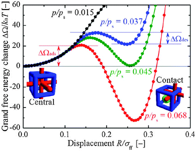 | ||
| Fig. 30 Grand free energy profiles of the interpenetrated framework along the displacement of one JG relative to the other, calculated for different relative pressures. (Reprinted with permission.205 Copyright 2009 American Institute of Physics.) | ||
A similar approach was taken to model the step-wise adsorption in [Cu(bipy)2(BF4)2]n (ELM-11)206 as a prototype system of a stacked layer MOF. In this case, the closed pored form is stable due to the interlayer attractive forces. By gradually increasing the interlayer width at different pressures free energy landscapes are obtained along a fixed trajectory. At p/p0 = 0 only one minimum is observed corresponding to the closed structure, at p/p0 = 0.10, a second local minimum appears caused by stabilization due to guest adsorption. Above p/p0 = 0.013 this becomes the global minimum and the open structure is stabilized by host guest interactions again resulting in a step-wise adsorption isotherm (gating). This approach also illustrates the pressure dependence of the activation energies and thus the width of the hysteresis with respect to pressure and temperature. It was concluded that the gate closing pressure is closer to the equilibrium transition pressure because the gate-closing activation energy is more sensitive to the bulk gas pressure. In general, at the lower temperature regime, the hysteresis width (in absolute pressure) increases with temperature but decreases again at higher temperature and finally vanishes because the energy fluctuation of the system becomes larger than the activation energy. Domain size effects were simulated by constructing a kinetic transition model resulting in pressure and domain size dependent rate constants that increase with pressure by more than 15 orders of magnitude.206 A smaller domain size produces a transition pressure closer to the equilibrium, whereas for large domain sizes a wide hysteresis is observed. Temperature dependence of the transition pressure was analyzed to deduce the enthalpy differences to reach the transient state.
Despite the deep insights resulting from these studies, they rely on a fixed trajectory of deformation, which is assumed for the simulation. Conventional modeling tools including molecular dynamics (MD) and GCMC techniques are not able to describe the complex interplay of the adsorption process and deformation in flexible MOFs simultaneously. GCMC methods typically allow a fluctuation of number of adsorbate molecules while considering the framework as rigid; MD simulations based on optimized force fields have been successfully applied to predict the structural forms present but for a fixed number of adsorbate molecules.207 To overcome this limitation, a hybrid osmotic Monte Carlo (HOMC) simulation was proposed combining MD and GCMC techniques.208 The method successfully reproduces the first lp → np transition in MIL-53(Cr) (CO2 adsorption) at pcalc = 0.35 bar (pexp = 0.30 bar) but fails to predict the reopening of the structure (np → lp). The latter was attributed to the difficulty in exploring the full phase space, due to the highly orientational ordered arrangement of the confined CO2 molecules along the channel axis. To overcome this limitation, a complementary macroscopic “phase mixture” model was included, which allowed to reproduce the full isotherm and both transitions. Such simulations reveal the subtle interplay between structural features of the host and phase transitions, such as translational or orientational ordering of the adsorbate molecules.201 In this way the microscopic identification of soft modes triggering the displacive transition and the corresponding mode frequency can be connected to the critical stress threshold value proposed in the stress-based model. First principles molecular dynamics simulations based on DFT Car–Parrinello are a powerful tool and were successfully used to model the water adsorption in MIL-53(Cr) by adding a fixed amount of water molecules to the empty framework.209 Typical hydrogen bond arrangements and structures of the host guest arrangement in the lp and np structure were illustrated.
Contrary to MIL-53(Al) and MIL-53(Cr) solids, the np phase is more thermodynamically stable for the MIL-53(Ga) material. In order to explain the phenomenon, Coudert et al. performed a theoretical investigation of both materials using quantum chemical calculations, Density Functional Theory based Molecular Dynamics (DFT-MD) and Thermodynamic Model Based on the Osmotic Ensemble.210 The energy minimization of both dehydrated frameworks shows that the np phase is more stable at low temperatures (Table 3).
| Δ (lp–np) | ΔEtot | ΔEel | ΔEdisp | ΔE0 | ΔSvib |
|---|---|---|---|---|---|
| Al-MIL-53 | 35.7 | −65.8 | 101.3 | 0.25 | 36.9 |
| Ga-MIL-53 | 39.6 | −53.3 | 94.5 | −1.61 | 33.8 |
The difference in ΔΔE ∼ 4 kJ mol−1 explains why the lp/np equilibrium temperature T0 is higher for Ga-MIL-53 (480 K) than for Al-MIL-53 (200 K).
Another approach was used by the authors to explain the difference in ΔEel and ΔEdisp for both materials. The additional calculations were performed on separated clusters, where all –OH groups and carboxylate ions are substituted by F− anions. It results in a full relaxation of the metal centers to an undistorted octahedral geometry. This relaxation is related to the energetic penalty for the distorted “narrow-pore” conformation of the metal coordination, corresponding to a change in the energy of 97.3 kJ mol−1 for Al, and 87.8 kJ mol−1 for Ga. The smaller value of the energetic penalty for Ga-MIL-53 is connected with more diffuse electronic orbitals of the latter. This difference was interpreted by the authors as a reason for a higher stability of the np form of Ga-MIL-53 at room temperature in comparison with its Al analogue.
In conclusion, the qualitative analysis and partially the quantitative description of thermodynamics in flexible MOFs are well developed. However, a detailed microscopic (atomistic) understanding of switching mechanisms and corresponding time scales is just at the beginning.
7. Applications
Although the industrial application of flexibility in MOFs is still not completely developed, two flexible materials are offered by Sigma-Aldrich under the names Basolite® A100 (MIL-53(Al) analogue) and Basolite® Z1200 (ZIF-8), correspondingly. However, several research papers highlight the potential application of flexibility in MOFs. The most prospective fields of (industrial) application are separation processes, biomedical application, chemical sensing, and catalysis.7.1. Separation
The dynamic pore system of flexible MOF materials makes them excellent candidates for application in different kinds of separation processes.150,187,211–222 The separation of gases, especially in energetically favorable pressure swing separation processes, can be one promising application for flexible MOFs, due to the adsorption discrepancy of different gases. Thus, the selective sorption of CO2 over O2 and N2 on flexible porous 2D framework CID-3, constructed from interdigitated [Zn(2,7-ndc)(bipy)]n layers (2,7-ndc = 2,7-naphthalene dicarboxylate) was discovered by Kitagawa et al.223 Adsorption experiments using CO2![[thin space (1/6-em)]](https://www.rsc.org/images/entities/char_2009.gif) :
:![[thin space (1/6-em)]](https://www.rsc.org/images/entities/char_2009.gif) O2
O2![[thin space (1/6-em)]](https://www.rsc.org/images/entities/char_2009.gif) :
:![[thin space (1/6-em)]](https://www.rsc.org/images/entities/char_2009.gif) N2 mixtures (in composition 1
N2 mixtures (in composition 1![[thin space (1/6-em)]](https://www.rsc.org/images/entities/char_2009.gif) :
:![[thin space (1/6-em)]](https://www.rsc.org/images/entities/char_2009.gif) 1
1![[thin space (1/6-em)]](https://www.rsc.org/images/entities/char_2009.gif) :
:![[thin space (1/6-em)]](https://www.rsc.org/images/entities/char_2009.gif) 1 and 1
1 and 1![[thin space (1/6-em)]](https://www.rsc.org/images/entities/char_2009.gif) :
:![[thin space (1/6-em)]](https://www.rsc.org/images/entities/char_2009.gif) 21
21![[thin space (1/6-em)]](https://www.rsc.org/images/entities/char_2009.gif) :
:![[thin space (1/6-em)]](https://www.rsc.org/images/entities/char_2009.gif) 78) show excellent separation performance of the material (Fig. 31). Although the concentration of CO2 is low in the last case, clear separation is observed. After reaching the breakpoint, the curve of CO2 smoothly returns to the initial intensity suggesting that the adsorption rate is relatively fast. The multiple adsorption experiments that were done on the same sample show the reproducibility of the results and reusability of the sample. The MIL-53(Al) material was also subjected to study CO2/N2 and CO2/CH4 separation.218,220 In case of CO2/N2 separation, the characteristic breathing behavior of amino-MIL-53(Al) for both CO2 and N2 in high-pressure gas adsorption measurements can be used for selective adsorption of CO2. Pressure swing adsorption–desorption cycles repeated six times between 0.5 and 2.0 MPa at 298 K in all cases showed no deterioration in CO2 adsorption capacities (291 mg g−1 at 2.0 MPa).
78) show excellent separation performance of the material (Fig. 31). Although the concentration of CO2 is low in the last case, clear separation is observed. After reaching the breakpoint, the curve of CO2 smoothly returns to the initial intensity suggesting that the adsorption rate is relatively fast. The multiple adsorption experiments that were done on the same sample show the reproducibility of the results and reusability of the sample. The MIL-53(Al) material was also subjected to study CO2/N2 and CO2/CH4 separation.218,220 In case of CO2/N2 separation, the characteristic breathing behavior of amino-MIL-53(Al) for both CO2 and N2 in high-pressure gas adsorption measurements can be used for selective adsorption of CO2. Pressure swing adsorption–desorption cycles repeated six times between 0.5 and 2.0 MPa at 298 K in all cases showed no deterioration in CO2 adsorption capacities (291 mg g−1 at 2.0 MPa).
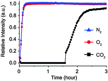 | ||
Fig. 31 Breakthrough curve for CID-3 for mixture CO2![[thin space (1/6-em)]](https://www.rsc.org/images/entities/char_2009.gif) : :![[thin space (1/6-em)]](https://www.rsc.org/images/entities/char_2009.gif) O2 O2![[thin space (1/6-em)]](https://www.rsc.org/images/entities/char_2009.gif) : :![[thin space (1/6-em)]](https://www.rsc.org/images/entities/char_2009.gif) N2 = 1 N2 = 1![[thin space (1/6-em)]](https://www.rsc.org/images/entities/char_2009.gif) : :![[thin space (1/6-em)]](https://www.rsc.org/images/entities/char_2009.gif) 21 21![[thin space (1/6-em)]](https://www.rsc.org/images/entities/char_2009.gif) : :![[thin space (1/6-em)]](https://www.rsc.org/images/entities/char_2009.gif) 78 at total pressure of 0.5 MPa. (Reproduced with permission.223 The Royal Society of Chemistry.) 78 at total pressure of 0.5 MPa. (Reproduced with permission.223 The Royal Society of Chemistry.) | ||
In the work of Rodrigue et al., MIL-53(Al) and its amino version were used to prepare MOF-based mixed matrix membranes for CO2/CH4 separation. 6FDA–ODA polyimide (6FDA = 4,4′-(hexafluoroisopropylidene)-diphthalic anhydride; ODA = 4,4′-oxydianiline) membranes containing Al-MIL-53-NH2 particles for CO2/CH4 separation display high ideal selectivities up to 77, and a high separation factor up to 53, which is comparable to inorganic filters (zeolite FAU/EMT) for CO2/CH4 separation. The same material was subjected to prepare a membrane, supported on macroporous glass for selective hydrogen adsorption from binary H2/CH4, H2/N2 and H2/CO2 mixtures.224 The membrane demonstrated to be highly selective for H2 permeation with a separation factor higher than 20, due to its specific sorption affinity and the competitive adsorption effect. Besides the separation of gas mixtures, MIL-53(Al) was successfully tested in liquid phase separation as a stationary phase for HPLC columns. Thus, Millange and coworkers used the flexibility of MIL-53(Fe) to separate a mixture of xylene isomers.219 In this case, the role of framework flexibility during the process was confirmed by structural analysis. In accordance with powder X-ray diffraction studies, the adsorption of each isomer leads to a fully expanded form of MIL-53(Fe) with a variety of host–guest and guest–guest interactions responsible for stabilizing the structure. The ortho- and meta-isomers show similar arrangements in the pores, while the para-isomer shows completely different host–guest interactions. This fact is underlined by testing the material under chromatographic conditions. As a result, only the para-isomer can be isolated at 293 K from the mixture. Remarkably, all components can be desorbed by increasing the temperature to 323 K.
These results are promising, but it should be acknowledged that often the selectivity is calculated from single component gas sorption isotherms. For gas mixtures, however, very complex flexible behavior can be observed. For example, for the MIL-53(Cr) system a high selectivity towards CO2 over CH4 was observed for the np phase, however the transition to the lp at higher working capacities leads to a low selectivity.167
Kitagawa and coworkers successfully showed the low energy separation of the strongly related gases CO and N2 in soft porous crystals.187 Namely, [Cu(aip)] adsorbs CO in a highly positive cooperative manner, accompanied by a structural transition to the lp phase. Oppositely, no structural changes were observed during the adsorption of N2 under the same conditions. The separation ability was confirmed using mixtures of N2 and CO (concentration of CO from 10%). A surprising enrichment of CO of 85% and 94% was achieved after the first and second cycles starting from a 1![[thin space (1/6-em)]](https://www.rsc.org/images/entities/char_2009.gif) :
:![[thin space (1/6-em)]](https://www.rsc.org/images/entities/char_2009.gif) 1 mixture of CO and N2, respectively.
1 mixture of CO and N2, respectively.
7.2. Biomedical application
Controlled drug release, allowing focused supply of the API (Active Pharmaceutical Ingredient) to the target organ or part of the body, is a challenging task of biomedicine. After discovering the physiological function of nitric monoxide, the problem of targeted delivery was recognized. Exploration of MOFs as drug delivery agents, especially as gas carriers (including NO), was widely studied recently.225 In particular, a high performance in NO storage under dry conditions was shown for HKUST-1, CPO-27(Ni), and CPO-27(Co) materials, containing open metal sites. Nevertheless, the application of such materials in vivo would be dubious, because they contain toxic metals, such as Cu, Ni or Co. Since iron is much less toxic compared to other metals, the iron based porous solids are more suitable for such applications. Recently, the group of Serre tested the iron based flexible MIL-88A as a NO carrier.226 The loaded structure remains closed, binding NO to the accessible iron metal sites. In situ IR adsorption confirms even chemisorption of NO molecules on open metal sites that ensures the loading capacities within the 1–2.5 mmol g−1 range. The release of NO in “wet gas” or solution has a prolonged effect, releasing biologically significant quantities (10 parts per billion (ppb)) of NO for up to 16 h after starting from the MOF. Thus, the biomedical application of flexible MOFs is still not developed significantly, mostly because of toxicity and instability of the frameworks under physiological conditions. Beside gas molecules, loading of flexible MOFs with solid APIs was studied by Horcajada et al.227 The ibuprofen was chosen as a model API that has to be adsorbed on biocompatible MIL-53(Fe). The diffraction study of the ibuprofen filled material agrees with the unit cell of MIL-53-lp phases. The delivery of ibuprofen was then performed using a simulated body fluid with inorganic composition similar to that of human plasma, at 37 °C under continuous stirring. Surprisingly, a very slow delivery is observed with clearly two steps in the process (Fig. 32). The slow kinetics of drug release could lead to a stable drug concentration in blood, a minimization of the toxicity effects, as well as a decrease in patient discomfort.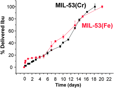 | ||
| Fig. 32 Depiction of the delivery of Ibuprofen from MIL-53(Cr) and MIL-53(Fe). (Reprinted with permission.227 Copyright 2008. American Chemical Society.) | ||
7.3. Sensing
The simplest imaginable sensor property of a flexible framework is a reversible color change upon structural transformation. For example, DUT-8(Ni) changes its color from yellow to green during the adsorption of CO2, n-butane, N2etc.96Another flexible ultramicroporous Co based MOF, [Co1.5(tipb)(SO4)(bdc)0.5]n (tipb = 1,3,5-tris(p-imidazolylphenyl)benzene) involves tetrahedrally coordinated Co atoms in its activated structure.228 The compound is highly responsive to H2O and NH3, showing reversible structural transformation associated with the change in the coordination geometry of Co from tetrahedral to octahedral. This is accompanied by a color change from blue to pink, occurring in a very narrow region of water vapor pressure (Fig. 33). A very promising flexible material, [Zn2(bdc)2(dpNDI)]n (dpNDI = N,N′-di(4-pyridyl)-1,4,5,8-naphthalenediimide), which is capable not only of detecting, but also of distinguishing between the target molecules was reported recently.229 Adsorption of aromatic volatile organic compounds (VOCs) leads to the structural transformation of the host framework. Further excitation of the VOCs@[Zn2(bdc)2(dpNDI)]n with 370 nm light leads to the characteristic emission bands over the entire visible region (420–600 nm), allowing to detect the difference with the naked eye. The difference in interactions between dpNDI and VOCs leads to the emission of light with the following wave lengths: 421 nm for benzonitrile, 439 nm for benzene, 476 nm for toluene, 496 nm for o-xylene, 503 nm for m-xylene, 518 nm for p-xylene, and 592 nm for anisole.
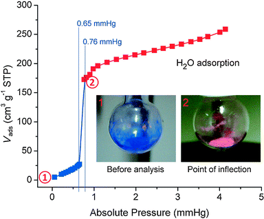 | ||
| Fig. 33 Color change of [Co1.5(tipb)(SO4)(bdc)0.5]n during H2O adsorption. (Reprinted with permission.228 Copyright 2012 John Wiley and Sons.) | ||
Another example of possible application of flexible MOFs in sensor technology was shown by Yanai et al.230 The composite material DSB@[Zn2(bdc)2dabco]n (DSB – distyrylbenzene) was used for the selective detection of CO2 and C2H2. Moreover, the composite shows different fluorescence responses to CO2 and acetylene, molecules that have similar physicochemical properties. In this case, the host–guest interactions play a key role in the sensing mechanism.
If the adsorption on a flexible MOF is accompanied by the size change of the crystallites, this deformation can also be used as a sensor signal.231
Moreover, in contrast to the rigid MOFs, the soft porous crystal can serve as a “smart” sensor, for monitoring and simultaneous adsorption of contaminants only when a certain threshold concentration (gate opening pressure) is reached.
7.4. Catalysis
Unfortunately the applicability of flexible MOFs in catalysis is not widely developed yet. Das et al. used a Gd based flexible MOF that serves as a heterogeneous catalyst in cyanosilylation and Knoevenagel condensation reactions, proceeding in the pores of the material.232 In this case, the flexibility of the MOF was used for the first time to monitor the catalytic reaction inside the pore by single crystal X-ray diffraction analysis (Fig. 34). When single crystals of the as synthesized compound were exposed to benzaldehyde vapor at ambient temperature for 5 days, benzaldehyde agglomerated inside the pore without a loss in the crystallinity of the framework and preservation of the coordination environment of the Gd2 dimeric unit and of the overall framework structure (Fig. 34), although the space group changed from P21/c to C2/c. When a single crystal of a compound loaded with the benzaldehyde was exposed to trimethylsilyl cyanide vapor for 2 h at ambient temperature, 2-hydroxy-2-phenylacetonitrile was formed inside the pores without loss in crystallinity. As a result, the coordination geometry around each metal center remained intact, whilst four trimethylsilylcyanide molecules reacted with the four benzaldehyde molecules to form cyanohydrin trimethylsilylether. The Knoevenagel condensation reaction was performed by exposing a single crystal of the benzaldehyde containing framework to malononitrile vapor for two hours, which yielded a framework containing 2-benzylidenemalononitrile, without loss in crystallinity. Therefore, this study shows a possibility to explore the pore system of (flexible) MOFs for observing chemically important reactions that can also be useful to study their mechanisms.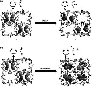 | ||
| Fig. 34 Single-crystal to single-crystal transition, observed for the cyanosilylation (a) and Knoevenagel condensation reactions (b) of benzaldehyde. The framework is shown as a ball and stick model; guest molecules are shown as CPK models. (Reprinted with permission.232 Copyright 2012 John Wiley and Sons.) | ||
8. Conclusions
Although a plethora of papers, presenting and discussing flexible MOFs and/or soft porous crystals and various concepts for designing unique functional properties – based on the materials “softness” and stimuli responsiveness even beyond simple host–guest interaction during adsorption–desorption – a comprehensive theory that involves all theoretical and experimental aspects of framework flexibility is still at its emerging state. The theory should be developed further, including scale bridging techniques to be able to not only explain, but also to predict the breathing behavior in MOFs and so support the experimental chemists with prospective structural models. Relying on the theoretical and experimental studies, the application potential, in particular in the field of low-energy and high selective gas separation, appears to be promising. A main challenge in the field of experimental chemistry of flexible MOFs guided by theoretical insight (i.e. molecular modeling) would be the directed synthesis of materials with pre-defined breathing/gate behavior and functionality. For system integration, thermally, magnetically or electrically switchable flexible materials are ideal for sensing and switching devices. In the field of characterization of flexible materials, sensible in situ methods should be further developed in order to identify and characterize the relevant host–host, host–guest and guest–guest interactions that play a key role in the various forms of flexible and dynamic processes.Acknowledgements
A. S. acknowledges the Research Cluster SusChemSys (http://www.cmt.rwth-aachen.de/projects.html) for a doctoral fellowship. A. S. and I. Sch. acknowledge C. Wiktor for helpful discussions. V. B. acknowledges the German Federal Ministry of Education and Research (Projects 05K10OD3 and 05K13OD3) for the financial support and Helmholtz-Zentrum Berlin für Materialien und Energie for the beamtime, allocated for in situ investigation of flexible MOFs. Finally, the authors wish to acknowledge funding by the German Research Foundation via the Priority Program 1362 “Metal–Organic Frameworks” (http://www.metal-organic-frameworks.de/).References
- J.-R. Li, J. Sculley and H.-C. Zhou, Chem. Rev., 2012, 112, 869 CrossRef CAS PubMed.
- H. Furukawa, K. E. Cordova, M. O'Keeffe and O. M. Yaghi, Science, 2013, 341, 974 CrossRef CAS PubMed.
- A. Schneemann, S. Henke, I. Schwedler and R. A. Fischer, ChemPhysChem, 2014, 15, 823 CrossRef CAS PubMed.
- M. Li, D. Li, M. O'Keeffe and O. M. Yaghi, Chem. Rev., 2014, 114, 1343 CrossRef CAS PubMed.
- S. Kitagawa and M. Kondo, Bull. Chem. Soc. Jpn., 1998, 71, 1739 CrossRef CAS.
- S. Horike, S. Shimomura and S. Kitagawa, Nat. Chem., 2009, 1, 695 CrossRef CAS PubMed.
- G. Ferey and C. Serre, Chem. Soc. Rev., 2009, 38, 1380 RSC.
- S. Kitagawa, R. Kitaura and S.-i. Noro, Angew. Chem., Int. Ed., 2004, 43, 2334 CrossRef CAS PubMed.
- S. Bureekaew, S. Shimomura and S. Kitagawa, Sci. Technol. Adv. Mater., 2008, 9, 014108 CrossRef.
- K. Uemura, R. Matsuda and S. Kitagawa, J. Solid State Chem., 2005, 178, 2420 CrossRef CAS PubMed.
- G. Ferey, Dalton Trans., 2009, 4400 RSC.
- C. R. Murdock, B. C. Hughes, Z. Lu and D. M. Jenkins, Coord. Chem. Rev., 2014, 258–259, 119 CrossRef CAS PubMed.
- A. J. Fletcher, K. M. Thomas and M. J. Rosseinsky, J. Solid State Chem., 2005, 178, 2491 CrossRef CAS PubMed.
- L. E. Kreno, K. Leong, O. K. Farha, M. Allendorf, R. P. Van Duyne and J. T. Hupp, Chem. Rev., 2012, 112, 1105 CrossRef CAS PubMed.
- D. Bousquet, F.-X. Coudert, A. G. J. Fossati, A. V. Neimark, A. H. Fuchs and A. Boutin, J. Chem. Phys., 2013, 138, 174706 CrossRef PubMed.
- F.-X. Coudert, A. Boutin, A. H. Fuchs and A. V. Neimark, J. Phys. Chem. Lett., 2013, 4, 3198 CrossRef CAS.
- T. Loiseau, C. Serre, C. Huguenard, G. Fink, F. Taulelle, M. Henry, T. Bataille and G. Ferey, Chem. – Eur. J., 2004, 10, 1373 CrossRef CAS PubMed.
- F. Millange, N. Guillou, R. I. Walton, J.-M. Greneche, I. Margiolaki and G. Ferey, Chem. Commun., 2008, 4732 RSC.
- F. Millange, C. Serre and G. Ferey, Chem. Commun., 2002, 822 RSC.
- C. Serre, F. Millange, C. Thouvenot, M. Nogues, G. Marsolier, D. Loueer and G. Ferey, J. Am. Chem. Soc., 2002, 124, 13519 CrossRef CAS PubMed.
- J. P. S. Mowat, V. R. Seymour, J. M. Griffin, S. P. Thompson, A. M. Z. Slawin, D. Fairen-Jimenez, T. Dueren, S. E. Ashbrook and P. A. Wright, Dalton Trans., 2012, 41, 3937 RSC.
- C. Volkringer, T. Loiseau, N. Guillou, G. Ferey, E. Elkaim and A. Vimont, Dalton Trans., 2009, 2241 RSC.
- E. V. Anokhina, M. Vougo-Zanda, X. Wang and A. J. Jacobson, J. Am. Chem. Soc., 2005, 127, 15000 CrossRef CAS PubMed.
- C. Mellot-Draznieks, C. Serre, S. Surble, N. Audebrand and G. Ferey, J. Am. Chem. Soc., 2005, 127, 16273 CrossRef CAS PubMed.
- S. Surble, C. Serre, C. Mellot-Draznieks, F. Millange and G. Ferey, Chem. Commun., 2006, 284 RSC.
- H. Li, M. Eddaoudi, M. O'Keeffe and M. Yaghi, Nature, 1999, 402, 276 CrossRef CAS PubMed.
- S. S. Y. Chui, S. M. F. Lo, J. P. H. Charmant, A. G. Orpen and I. D. Williams, Science, 1999, 283, 1148 CrossRef CAS.
- D. Fairen-Jimenez, S. A. Moggach, M. T. Wharmby, P. A. Wright, S. Parsons and T. Duren, J. Am. Chem. Soc., 2011, 133, 8900 CrossRef CAS PubMed.
- G. Garberoglio and S. Taioli, Microporous Mesoporous Mater., 2012, 163, 215 CrossRef CAS PubMed.
- D. Fairen-Jimenez, R. Galvelis, A. Torrisi, A. D. Gellan, M. T. Wharmby, P. A. Wright, C. Mellot-Draznieks and T. Dueren, Dalton Trans., 2012, 41, 10752 RSC.
- J. Seo, R. Matsuda, H. Sakamoto, C. Bonneau and S. Kitagawa, J. Am. Chem. Soc., 2009, 131, 12792 CrossRef CAS PubMed.
- T. K. Maji, R. Matsuda and S. Kitagawa, Nat. Mater., 2007, 6, 142 CrossRef CAS PubMed.
- P. Kanoo, R. Matsuda, M. Higuchi, S. Kitagawa and T. K. Maji, Chem. Mater., 2009, 21, 5860 CrossRef CAS.
- S. Bureekaew, H. Sato, R. Matsuda, Y. Kubota, R. Hirose, J. Kim, K. Kato, M. Takata and S. Kitagawa, Angew. Chem., Int. Ed., 2010, 49, 7660 CrossRef CAS PubMed.
- R. Kitaura, K. Seki, G. Akiyama and S. Kitagawa, Angew. Chem., Int. Ed., 2003, 42, 428 CrossRef CAS PubMed.
- O. K. Farha, I. Eryazici, N. C. Jeong, B. G. Hauser, C. E. Wilmer, A. A. Sarjeant, R. Q. Snurr, S. T. Nguyen, A. O. Yazaydin and J. T. Hupp, J. Am. Chem. Soc., 2012, 134, 15016 CrossRef CAS PubMed.
- R. K. Deshpande, J. L. Minnaar and S. G. Telfer, Angew. Chem., Int. Ed., 2010, 49, 4598 CrossRef CAS PubMed.
- R. K. Deshpande, G. I. N. Waterhouse, G. B. Jameson and S. G. Telfer, Chem. Commun., 2012, 48, 1574 RSC.
- S. Ma, D. Sun, M. Ambrogio, J. A. Fillinger, S. Parkin and H.-C. Zhou, J. Am. Chem. Soc., 2007, 129, 1858 CrossRef CAS PubMed.
- J. L. C. Rowsell and O. M. Yaghi, J. Am. Chem. Soc., 2006, 128, 1304 CrossRef CAS PubMed.
- J. L. C. Rowsell and O. M. Yaghi, Angew. Chem., Int. Ed., 2005, 44, 4670 CrossRef CAS PubMed.
- S. Yang, X. Lin, W. Lewis, M. Suyetin, E. Bichoutskaia, J. E. Parker, C. C. Tang, D. R. Allan, P. J. Rizkallah, P. Hubberstey, N. R. Champness, K. M. Thomas, A. J. Blake and M. Schroeder, Nat. Mater., 2012, 11, 710 CrossRef CAS PubMed.
- A. Modrow, D. Zargarani, R. Herges and N. Stock, Dalton Trans., 2011, 40, 4217 RSC.
- J. W. Brown, B. L. Henderson, M. D. Kiesz, A. C. Whalley, W. Morris, S. Grunder, H. Deng, H. Furukawa, J. I. Zink, J. F. Stoddart and O. M. Yaghi, Chem. Sci., 2013, 4, 2858 RSC.
- J. Park, D. Yuan, K. T. Pham, J.-R. Li, A. Yakovenko and H.-C. Zhou, J. Am. Chem. Soc., 2012, 134, 99 CrossRef CAS PubMed.
- N. Yanai, T. Uemura, M. Inoue, R. Matsuda, T. Fukushima, M. Tsujimoto, S. Isoda and S. Kitagawa, J. Am. Chem. Soc., 2012, 134, 4501 CrossRef CAS PubMed.
- K. Uemura, Y. Yamasaki, Y. Komagawa, K. Tanaka and H. Kita, Angew. Chem., Int. Ed., 2007, 46, 6662 CrossRef CAS PubMed.
- R. Lyndon, K. Konstas, B. P. Ladewig, P. D. Southon, C. J. Kepert and M. R. Hill, Angew. Chem., Int. Ed., 2013, 52, 3695 CrossRef CAS PubMed.
- Y. Liu, J.-H. Her, A. Dailly, J. Ramirez-Cuesta Anibal, A. Neumann Dan and M. Brown Craig, J. Am. Chem. Soc., 2008, 130, 11813 CrossRef CAS PubMed.
- A. M. Walker, B. Civalleri, B. Slater, C. Mellot-Draznieks, F. Cora, C. M. Zicovich-Wilson, G. Roman-Perez, J. M. Soler and J. D. Gale, Angew. Chem., Int. Ed., 2010, 49, 7501 CrossRef CAS PubMed.
- I. E. Collings, A. B. Cairns, A. L. Thompson, J. E. Parker, C. C. Tang, M. G. Tucker, J. Catafesta, C. Levelut, J. Haines, V. Dmitriev, P. Pattison and A. L. Goodwin, J. Am. Chem. Soc., 2013, 135, 7610 CrossRef CAS PubMed.
- W. Zhou, H. Wu, T. Yildirim, J. R. Simpson and A. R. Hight Walker, Phys. Rev. B: Condens. Matter Mater. Phys., 2008, 78, 054114 CrossRef.
- Y. Wu, A. Kobayashi, G. J. Halder, V. K. Peterson, K. W. Chapman, N. Lock, P. D. Southon and C. J. Kepert, Angew. Chem., Int. Ed., 2008, 47, 8929 CrossRef CAS PubMed.
- J. M. Ogborn, I. E. Collings, S. A. Moggach, A. L. Thompson and A. L. Goodwin, Chem. Sci., 2012, 3, 3011 RSC.
- L. D. DeVries, P. M. Barron, E. P. Hurley, C. Hu and W. Choe, J. Am. Chem. Soc., 2013, 133, 14848 CrossRef PubMed.
- C. Yang, X. Wang and M. A. Omary, Angew. Chem., Int. Ed., 2009, 48, 2500 CrossRef CAS PubMed.
- S. Henke, A. Schneemann and R. A. Fischer, Adv. Funct. Mater., 2013, 23, 5990 CrossRef CAS.
- T. D. Keene, D. Rankine, J. D. Evans, P. D. Southon, C. J. Kepert, J. B. Aitken, C. J. Sumby and C. J. Doonan, Dalton Trans., 2013, 42, 7871 RSC.
- I. Grobler, V. J. Smith, P. M. Bhatt, S. A. Herbert and L. J. Barbour, J. Am. Chem. Soc., 2013, 135, 6411 CrossRef CAS PubMed.
- A. L. Goodwin, M. Calleja, M. J. Conterio, M. T. Dove, J. S. O. Evans, D. A. Keen, L. Peters and M. G. Tucker, Science, 2008, 319, 794 CrossRef CAS PubMed.
- A. L. Goodwin and C. J. Kepert, Phys. Rev. B: Condens. Matter Mater. Phys., 2005, 71, 140301 CrossRef.
- D. N. Dybtsev, H. Chun and K. Kim, Angew. Chem., Int. Ed., 2004, 43, 5033 CrossRef CAS PubMed.
- T. D. Bennett, D. A. Keen, J.-C. Tan, E. R. Barney, A. L. Goodwin and A. K. Cheetham, Angew. Chem., Int. Ed., 2011, 50, 3067 CrossRef CAS PubMed.
- J. C. Tan and A. K. Cheetham, Chem. Soc. Rev., 2011, 40, 1059 RSC.
- K. W. Chapman, D. F. Sava, G. J. Halder, P. J. Chupas and T. M. Nenoff, J. Am. Chem. Soc., 2011, 133, 18583 CrossRef CAS PubMed.
- K. W. Chapman, G. J. Halder and P. J. Chupas, J. Am. Chem. Soc., 2009, 131, 17546 CrossRef CAS PubMed.
- S. A. Moggach, T. D. Bennett and A. K. Cheetham, Angew. Chem., Int. Ed., 2009, 48, 7087 CrossRef CAS PubMed.
- K. W. Chapman, G. J. Halder and P. J. Chupas, J. Am. Chem. Soc., 2008, 130, 10524 CrossRef CAS PubMed.
- W. Li, M. R. Probert, M. Kosa, T. D. Bennett, A. Thirumurugan, R. P. Burwood, M. Parinello, J. A. K. Howard and A. K. Cheetham, J. Am. Chem. Soc., 2012, 134, 11940 CrossRef CAS PubMed.
- K. J. Gagnon, C. M. Beavers and A. Clearfield, J. Am. Chem. Soc., 2013, 135, 1252 CrossRef CAS PubMed.
- A. L. Goodwin, D. A. Keen and M. G. Tucker, Proc. Natl. Acad. Sci. U. S. A., 2008, 105, 18708 CrossRef CAS PubMed.
- P. G. Yot, Q. Ma, J. Haines, Q. Yang, A. Ghoufi, T. Devic, C. Serre, V. Dmitriev, G. Ferey, C. Zhong and G. Maurin, Chem. Sci., 2012, 3, 1100 RSC.
- I. Beurroies, M. Boulhout, P. L. Llewellyn, B. Kuchta, G. Ferey, C. Serre and R. Denoyel, Angew. Chem., Int. Ed., 2010, 49, 7526 CrossRef CAS PubMed.
- H. Uehara, S. Diring, S. Furukawa, Z. Kalay, M. Tsotsalas, M. Nakahama, K. Hirai, M. Kondo, O. Sakata and S. Kitagawa, J. Am. Chem. Soc., 2011, 133, 11932 CrossRef CAS PubMed.
- T. D. Bennett, S. Cao, J. C. Tan, D. A. Keen, E. G. Bithell, P. J. Beldon, T. Friscic and A. K. Cheetham, J. Am. Chem. Soc., 2011, 133, 14546 CrossRef CAS PubMed.
- Y. Sakata, S. Furukawa, M. Kondo, K. Hirai, N. Horike, Y. Takashima, H. Uehara, N. Louvain, M. Meilikhov, T. Tsuruoka, S. Isoda, W. Kosaka, O. Sakata and S. Kitagawa, Science, 2013, 339, 193 CrossRef CAS PubMed.
- D. Tanaka, A. Henke, K. Albrecht, M. Moeller, K. Nakagawa, S. Kitagawa and J. Groll, Nat. Chem., 2010, 2, 410 CrossRef CAS PubMed.
- Y. Hijikata, S. Horike, D. Tanaka, J. Groll, M. Mizuno, J. Kim, M. Takata and S. Kitagawa, Chem. Commun., 2011, 47, 7632 RSC.
- A. Betard and R. A. Fischer, Chem. Rev., 2012, 112, 1055 CrossRef CAS PubMed.
- C. Scherb, R. Koehn and T. Bein, J. Mater. Chem., 2010, 20, 3046 RSC.
- I. Senkovska, F. Hoffmann, M. Fröba, J. Getzschmann, W. Böhlmann and S. Kaskel, Microporous Mesoporous Mater., 2009, 122, 93 CrossRef CAS PubMed.
- T. Loiseau, C. Mellot-Draznieks, H. Muguerra, G. Ferey, M. Haouas and F. Taulelle, C. R. Chim., 2005, 8, 765 CrossRef CAS PubMed.
- S. Bourrelly, P. L. Llewellyn, C. Serre, F. Millange, T. Loiseau and G. Ferey, J. Am. Chem. Soc., 2005, 127, 13519 CrossRef CAS PubMed.
- H. Leclerc, T. Devic, S. Devautour-Vinot, P. Bazin, N. Audebrand, G. Ferey, M. Daturi, A. Vimont and G. Clet, J. Phys. Chem. C, 2011, 115, 19828 CAS.
- G. Ferey, C. Serre, C. Mellot-Draznieks, F. Millange, S. Surble, J. Dutour and I. Margiolaki, Angew. Chem., Int. Ed., 2004, 43, 6296 CrossRef CAS PubMed.
- G. Ferey, C. Mellot-Draznieks, C. Serre, F. Millange, J. Dutour, S. Surble and I. Margiolaki, Science, 2005, 309, 2040 CrossRef CAS PubMed.
- C. Serre, F. Millange, S. Surble and G. Ferey, Angew. Chem., Int. Ed., 2004, 43, 6286 CrossRef CAS PubMed.
- J. Seo, C. Bonneau, R. Matsuda, M. Takata and S. Kitagawa, J. Am. Chem. Soc., 2011, 133, 9005 CrossRef CAS PubMed.
- K. Seki and W. Mori, J. Phys. Chem. B, 2002, 106, 1380 CrossRef CAS.
- R. Kitaura, F. Iwahori, R. Matsuda, S. Kitagawa, Y. Kubota, M. Takata and T. C. Kobayashi, Inorg. Chem., 2004, 43, 6522 CrossRef CAS PubMed.
- D. Tanaka, M. Higuchi, S. Horike, R. Matsuda, Y. Kinoshita, N. Yanai and S. Kitagawa, Chem. – Asian J., 2008, 3, 1343 CrossRef CAS PubMed.
- H. Wang, J. Getzschmann, I. Senkovska and S. Kaskel, Microporous Mesoporous Mater., 2008, 116, 653 CrossRef CAS PubMed.
- H. Sakamoto, R. Kitaura, R. Matsuda, S. Kitagawa, Y. Kubota and M. Takata, Chem. Lett., 2010, 39, 218 CrossRef CAS.
- P. Kanoo, G. Mostafa, R. Matsuda, S. Kitagawa and T. Kumar Maji, Chem. Commun., 2011, 47, 8106 RSC.
- N. Klein, H. C. Hoffmann, A. Cadiau, J. Getzschmann, M. R. Lohe, S. Paasch, T. Heydenreich, K. Adil, I. Senkovska, E. Brunner and S. Kaskel, J. Mater. Chem., 2012, 22, 10303 RSC.
- N. Klein, C. Herzog, M. Sabo, I. Senkovska, J. Getzschmann, S. Paasch, M. R. Lohe, E. Brunner and S. Kaskel, Phys. Chem. Chem. Phys., 2010, 12, 11778 RSC.
- A. Pichon, C. M. Fierro, M. Nieuwenhuyzen and S. L. James, CrystEngComm, 2007, 9, 449 RSC.
- D. N. Dybtsev, H. Chun and K. Kim, Angew. Chem., Int. Ed., 2004, 43, 5033 CrossRef CAS PubMed.
- A. V. Neimark, F.-X. Coudert, A. Boutin and A. H. Fuchs, J. Phys. Chem. Lett., 2009, 1, 445 CrossRef.
- K. C. Stylianou, J. Rabone, S. Y. Chong, R. Heck, J. Armstrong, P. V. Wiper, K. E. Jelfs, S. Zlatogorsky, J. Bacsa, A. G. McLennan, C. P. Ireland, Y. Z. Khimyak, K. M. Thomas, D. Bradshaw and M. J. Rosseinsky, J. Am. Chem. Soc., 2012, 134, 20466 CrossRef CAS PubMed.
- H. J. Park and M. P. Suh, Chem. Commun., 2010, 46, 610 RSC.
- V. Bon, I. Senkovska, D. Wallacher, D. M. Toebbens, I. Zizak, R. Feyerherm, U. Mueller and S. Kaskel, Inorg. Chem., 2014, 53, 1513 CrossRef CAS PubMed.
- M. Eddaoudi, J. Kim, N. Rosi, D. Vodak, J. Wachter, M. O'Keeffe and O. M. Yaghi, Science, 2002, 295, 469 CrossRef CAS PubMed.
- S. Biswas, T. Ahnfeldt and N. Stock, Inorg. Chem., 2012, 50, 9518 CrossRef PubMed.
- S. Biswas, T. Remy, S. Couck, D. Denysenko, G. Rampelberg, J. F. M. Denayer, D. Volkmer, C. Detavernier and P. Van Der Voort, Phys. Chem. Chem. Phys., 2013, 15, 3552 RSC.
- S. Biswas and P. Van Der Voort, Eur. J. Inorg. Chem., 2013, 2154 CrossRef CAS.
- S. Biswas, J. Zhang, Z. Li, Y.-Y. Liu, M. Grzywa, L. Sun, D. Volkmer and P. Van Der Voort, Dalton Trans., 2013, 42, 4730 RSC.
- S. J. Garibay and S. M. Cohen, Chem. Commun., 2010, 46, 7700 RSC.
- S. T. Meek, S. L. Teich-McGoldrick, J. J. Perry, J. A. Greathouse and M. D. Allendorf, J. Phys. Chem. C, 2012, 116, 19765 CAS.
- P. Serra-Crespo, E. Gobechiya, E. V. Ramos-Fernandez, J. Juan-Alcaniz, A. Martinez-Joaristi, E. Stavitski, C. E. A. Kirschhock, J. A. Martens, F. Kapteijn and J. Gascon, Langmuir, 2012, 28, 12916 CrossRef CAS PubMed.
- S. Henke, A. Schneemann, S. Kapoor, R. Winter and R. A. Fischer, J. Mater. Chem., 2012, 22, 909 RSC.
- M. Kim, J. A. Boissonnault, P. V. Dau and S. M. Cohen, Angew. Chem., Int. Ed., 2011, 50, 12193 CrossRef CAS PubMed.
- P. V. Dau, L. R. Polanco and S. M. Cohen, Dalton Trans., 2013, 42, 4013 RSC.
- K. Hindelang, A. Kronast, S. I. Vagin and B. Rieger, Chem. – Eur. J., 2013, 19, 8244 CrossRef CAS PubMed.
- K. Hindelang, S. I. Vagin, C. Anger and B. Rieger, Chem. Commun., 2012, 48, 2888 RSC.
- K. Hirai, S. Furukawa, M. Kondo, M. Meilikhov, Y. Sakata, O. Sakata and S. Kitagawa, Chem. Commun., 2012, 48, 6472 RSC.
- G. Tuci, A. Rossin, X. Xu, M. Ranocchiari, J. A. van Bokhoven, L. Luconi, I. Manet, M. Melucci and G. Giambastiani, Chem. Mater., 2013, 25, 2297 CrossRef CAS.
- A. D. Burrows, C. G. Frost, M. F. Mahon and C. Richardson, Chem. Commun., 2009, 4218 RSC.
- S. M. Cohen, Chem. Sci., 2010, 1, 32 RSC.
- T. Gadzikwa, K. Farha Omar, D. Malliakas Christos, G. Kanatzidis Mercouri, T. Hupp Joseph and T. Nguyen SonBinh, J. Am. Chem. Soc., 2009, 131, 13613 CrossRef CAS PubMed.
- T. Gadzikwa, G. Lu, C. L. Stern, S. R. Wilson, J. T. Hupp and S. T. Nguyen, Chem. Commun., 2008, 5493 RSC.
- Y. Goto, H. Sato, S. Shinkai and K. Sada, J. Am. Chem. Soc., 2008, 130, 14354 CrossRef CAS PubMed.
- M. Savonnet, D. Bazer-Bachi, N. Bats, J. Perez-Pellitero, E. Jeanneau, V. Lecocq, C. Pinel and D. Farrusseng, J. Am. Chem. Soc., 2010, 132, 4518 CrossRef CAS PubMed.
- Z. Wang and S. M. Cohen, J. Am. Chem. Soc., 2007, 129, 12368 CrossRef CAS PubMed.
- J. G. Nguyen and S. M. Cohen, J. Am. Chem. Soc., 2010, 132, 4560 CrossRef CAS PubMed.
- Z. Wang and S. M. Cohen, Angew. Chem., Int. Ed., 2008, 47, 4699 CrossRef CAS PubMed.
- C. A. Allen and S. M. Cohen, J. Mater. Chem., 2012, 22, 10188 RSC.
- K. K. Tanabe, C. A. Allen and S. M. Cohen, Angew. Chem., Int. Ed., 2010, 49, 9730 CrossRef CAS PubMed.
- M. Kim, J. F. Cahill, H. Fei, K. A. Prather and S. M. Cohen, J. Am. Chem. Soc., 2012, 134, 18082 CrossRef CAS PubMed.
- M. Kim, J. F. Cahill, Y. Su, K. A. Prather and S. M. Cohen, Chem. Sci., 2012, 3, 126 RSC.
- S. Takaishi, E. J. DeMarco, M. J. Pellin, O. K. Farha and J. T. Hupp, Chem. Sci., 2013, 4, 1509 RSC.
- O. Karagiaridi, W. Bury, A. A. Sarjeant, C. L. Stern, O. K. Farha and J. T. Hupp, Chem. Sci., 2012, 3, 3256 RSC.
- O. Karagiaridi, W. Bury, E. Tylianakis, A. A. Sarjeant, J. T. Hupp and O. K. Farha, Chem. Mater., 2013, 25, 3499 CrossRef CAS.
- O. Karagiaridi, M. B. Lalonde, W. Bury, A. A. Sarjeant, O. K. Farha and J. T. Hupp, J. Am. Chem. Soc., 2012, 134, 18790 CrossRef CAS PubMed.
- S. Pullen, H. Fei, A. Orthaber, S. M. Cohen and S. Ott, J. Am. Chem. Soc., 2013, 135, 16997 CrossRef CAS PubMed.
- S. Biswas, T. Ahnfeldt and N. Stock, Inorg. Chem., 2011, 50, 9518 CrossRef CAS PubMed.
- T. Devic, P. Horcajada, C. Serre, F. Salles, G. Maurin, B. Moulin, D. Heurtaux, G. Clet, A. Vimont, J.-M. Greneche, B. Le Ouay, F. Moreau, E. Magnier, Y. Filinchuk, J. Marrot, J.-C. Lavalley, M. Daturi and G. Ferey, J. Am. Chem. Soc., 2010, 132, 1127 CrossRef CAS PubMed.
- S. Henke, A. Schneemann, A. Wuetscher and R. A. Fischer, J. Am. Chem. Soc., 2012, 134, 9464 CrossRef CAS PubMed.
- Z. Wang and S. M. Cohen, J. Am. Chem. Soc., 2009, 131, 16675 CrossRef CAS PubMed.
- P. Horcajada, F. Salles, S. Wuttke, T. Devic, D. Heurtaux, G. Maurin, A. Vimont, M. Daturi, O. David, E. Magnier, N. Stock, Y. Filinchuk, D. Popov, C. Riekel, G. Ferey and C. Serre, J. Am. Chem. Soc., 2011, 133, 17839 CrossRef CAS PubMed.
- P. V. Dau and S. M. Cohen, CrystEngComm, 2013, 15, 9304 RSC.
- P. V. Dau, M. Kim, S. J. Garibay, F. H. L. Munch, C. E. Moore and S. M. Cohen, Inorg. Chem., 2012, 51, 5671 CrossRef CAS PubMed.
- A. D. Burrows, CrystEngComm, 2011, 13, 3623 RSC.
- O. Kozachuk, K. Khaletskaya, M. Halbherr, A. Betard, M. Meilikhov, R. W. Seidel, B. Jee, A. Poeppl and R. A. Fischer, Eur. J. Inorg. Chem., 2012, 1688 CrossRef CAS.
- W. Kleist, F. Jutz, M. Maciejewski and A. Baiker, Eur. J. Inorg. Chem., 2009, 3552 CrossRef CAS.
- M. I. Breeze, G. Clet, B. C. Campo, A. Vimont, M. Daturi, J.-M. Greneche, A. J. Dent, F. Millange and R. I. Walton, Inorg. Chem., 2013, 52, 8171 CrossRef CAS PubMed.
- H. Deng, C. J. Doonan, H. Furukawa, R. B. Ferreira, J. Towne, C. B. Knobler, B. Wang and O. M. Yaghi, Science, 2010, 327, 846 CrossRef CAS PubMed.
- X. Kong, H. Deng, F. Yan, J. Kim, J. A. Swisher, B. Smit, O. M. Yaghi and J. A. Reimer, Science, 2013, 341, 882 CrossRef CAS PubMed.
- T. Fukushima, S. Horike, H. Kobayashi, M. Tsujimoto, S. Isoda, M. L. Foo, Y. Kubota, M. Takata and S. Kitagawa, J. Am. Chem. Soc., 2012, 134, 13341 CrossRef CAS PubMed.
- T. Fukushima, S. Horike, Y. Inubushi, K. Nakagawa, Y. Kubota, M. Takata and S. Kitagawa, Angew. Chem., Int. Ed., 2010, 49, 4820 CrossRef CAS PubMed.
- F. Nouar, T. Devic, H. Chevreau, N. Guillou, E. Gibson, G. Clet, M. Daturi, A. Vimont, J. M. Greneche, M. I. Breeze, R. I. Walton, P. L. Llewellyn and C. Serre, Chem. Commun., 2012, 48, 10237 RSC.
- O. Kozachuk, M. Meilikhov, K. Yusenko, A. Schneemann, B. Jee, A. V. Kuttatheyil, M. Bertmer, C. Sternemann, A. Poeppl and R. A. Fischer, Eur. J. Inorg. Chem., 2013, 4546 CrossRef CAS.
- T. Lescouet, E. Kockrick, G. Bergeret, M. Pera-Titus, S. Aguado and D. Farrusseng, J. Mater. Chem., 2012, 22, 10287 RSC.
- S. R. Miller, P. A. Wright, T. Devic, C. Serre, G. r. Férey, P. L. Llewellyn, R. Denoyel, L. Gaberova and Y. Filinchuk, Langmuir, 2009, 25, 3618 CrossRef CAS PubMed.
- P. K. Allan, B. Xiao, S. J. Teat, J. W. Knight and R. E. Morris, J. Am. Chem. Soc., 2010, 132, 3605 CrossRef CAS PubMed.
- M. Kondo, S. Furukawa, K. Hirai, T. Tsuruoka, J. Reboul, H. Uehara, S. Diring, Y. Sakata, O. Sakata and S. Kitagawa, J. Am. Chem. Soc., 2014, 136, 4938 CrossRef CAS PubMed.
- Y. Kubota, M. Takata, R. Matsuda, R. Kitaura, S. Kitagawa and T. C. Kobayashi, Angew. Chem., Int. Ed., 2006, 45, 4932 CrossRef CAS PubMed.
- W. Yang, A. J. Davies, X. Lin, M. Suyetin, R. Matsuda, A. J. Blake, C. Wilson, W. Lewis, J. E. Parker, C. C. Tang, M. W. George, P. Hubberstey, S. Kitagawa, H. Sakamoto, E. Bichoutskaia, N. R. Champness, S. Yang and M. Schroder, Chem. Sci., 2012, 3, 2993 RSC.
- A. Kondo, H. Noguchi, L. Carlucci, D. M. Proserpio, G. Ciani, H. Kajiro, T. Ohba, H. Kanoh and K. Kaneko, J. Am. Chem. Soc., 2007, 129, 12362 CrossRef CAS PubMed.
- S. Henke, D. C. F. Wieland, M. Meilikhov, M. Paulus, C. Sternemann, K. Yusenko and R. A. Fischer, CrystEngComm, 2011, 13, 6399 RSC.
- T. R. Jensen, T. K. Nielsen, Y. Filinchuk, J.-E. Jorgensen, Y. Cerenius, E. M. Gray and C. J. Webb, J. Appl. Crystallogr., 2010, 43, 1456 CrossRef CAS PubMed.
- V. Bon, I. Senkovska, D. Wallacher, A. Heerwig, N. Klein, I. Zizak, R. Feyerherm, E. Dudzik and S. Kaskel, Microporous Mesoporous Mater., 2014, 188, 190 CrossRef CAS PubMed.
- C. Serre, S. Bourrelly, A. Vimont, N. A. Ramsahye, G. Maurin, P. L. Llewellyn, M. Daturi, Y. Filinchuk, O. Leynaud, P. Barnes and G. Ferey, Adv. Mater., 2007, 19, 2246 CrossRef CAS.
- T. K. Trung, P. Trens, N. Tanchoux, S. Bourrelly, P. L. Llewellyn, S. Loera-Serna, C. Serre, T. Loiseau, F. Fajula and G. Ferey, J. Am. Chem. Soc., 2008, 130, 16926 CrossRef CAS PubMed.
- P. L. Llewellyn, G. Maurin, T. Devic, S. Loera-Serna, N. Rosenbach, C. Serre, S. Bourrelly, P. Horcajada, Y. Filinchuk and G. Ferey, J. Am. Chem. Soc., 2008, 130, 12808 CrossRef CAS PubMed.
- P. L. Llewellyn, P. Horcajada, G. Maurin, T. Devic, N. Rosenbach, S. Bourrelly, C. Serre, D. Vincent, S. Loera-Serna, Y. Filinchuk and G. Ferey, J. Am. Chem. Soc., 2009, 131, 13002 CrossRef CAS PubMed.
- L. Hamon, P. L. Llewellyn, T. Devic, A. Ghoufi, G. Clet, V. Guillerm, G. D. Pirngruber, G. Maurin, C. Serre, G. Driver, W. van Beek, E. Jolimaitre, A. Vimont, M. Daturi and G. Ferey, J. Am. Chem. Soc., 2009, 131, 17490 CrossRef CAS PubMed.
- N. Rosenbach, Jr., H. Jobic, A. Ghoufi, F. Salles, G. Maurin, S. Bourrelly, P. L. Llewellyn, T. Devic, C. Serre and G. Ferey, Angew. Chem., Int. Ed., 2008, 47, 6611 CrossRef PubMed.
- A. S. Munn, A. J. Ramirez-Cuesta, F. Millange and R. I. Walton, Chem. Phys., 2013, 427, 30 CrossRef CAS PubMed.
- L. Chen, J. P. S. Mowat, D. Fairen-Jimenez, C. A. Morrison, S. P. Thompson, P. A. Wright and T. Duren, J. Am. Chem. Soc., 2013, 135, 15763 CrossRef CAS PubMed.
- B. Van de Voorde, A. S. Munn, N. Guillou, F. Millange, D. E. De Vos and R. I. Walton, Phys. Chem. Chem. Phys., 2013, 15, 8606 RSC.
- A. Boutin, D. Bousquet, A. U. Ortiz, F.-X. Coudert, A. H. Fuchs, A. Ballandras, G. Weber, I. Bezverkhyy, J.-P. Bellat, G. Ortiz, G. Chaplais, J.-L. Paillaud, C. Marichal, H. Nouali and J. Patarin, J. Phys. Chem. C, 2013, 117, 8180 CAS.
- T. Devic, F. Salles, S. Bourrelly, B. Moulin, G. Maurin, P. Horcajada, C. Serre, A. Vimont, J.-C. Lavalley, H. Leclerc, G. Clet, M. Daturi, P. L. Llewellyn, Y. Filinchuk and G. Ferey, J. Mater. Chem., 2012, 22, 10266 RSC.
- R. I. Walton, A. S. Munn, N. Guillou and F. Millange, Chem. – Eur. J., 2011, 17, 7069 CrossRef CAS PubMed.
- F. M. Mulder, B. Assfour, J. Huot, T. J. Dingemans, M. Wagemaker and A. J. Ramirez-Cuesta, J. Phys. Chem. C, 2010, 114, 10648 CAS.
- S. Bourrelly, B. Moulin, A. Rivera, G. Maurin, S. Devautour-Vinot, C. Serre, T. Devic, P. Horcajada, A. Vimont, G. Clet, M. Daturi, J.-C. Lavalley, S. Loera-Serna, R. Denoyel, P. L. Llewellyn and G. Ferey, J. Am. Chem. Soc., 2010, 132, 9488 CrossRef CAS PubMed.
- J.-L. Bonardet, J. Fraissard, A. Gédéon and M.-A. Springuel-Huet, Catal. Rev.: Sci. Eng., 1999, 41, 115 CAS.
- H. C. Hoffmann, M. Debowski, P. Müller, S. Paasch, I. Senkovska, S. Kaskel and E. Brunner, Materials, 2012, 5, 2537 CrossRef CAS PubMed.
- M.-A. Springuel-Huet, A. Nossov, Z. Adem, F. Guenneau, C. Volkringer, T. Loiseau, G. Férey and A. Gédéon, J. Am. Chem. Soc., 2010, 132, 11599 CrossRef CAS PubMed.
- H. C. Hoffmann, B. Assfour, F. Epperlein, N. Klein, S. Paasch, I. Senkovska, S. Kaskel, G. Seifert and E. Brunner, J. Am. Chem. Soc., 2011, 133, 8681 CrossRef CAS PubMed.
- M.-A. Springuel-Huet, A. Nossov, F. Guenneau and A. Gédéon, Chem. Commun., 2013, 49, 7403 RSC.
- X. Kong, E. Scott, W. Ding, J. A. Mason, J. R. Long and J. A. Reimer, J. Am. Chem. Soc., 2012, 134, 14341 CrossRef CAS PubMed.
- E. Stavitski and B. M. Weckhuysen, Chem. Soc. Rev., 2010, 39, 4615 RSC.
- W. van Beek, O. V. Safonova, G. Wiker and H. Emerich, Phase Transitions, 2011, 84, 726 CrossRef CAS.
- F. Salles, G. Maurin, C. Serre, P. L. Llewellyn, C. Knofel, H. J. Choi, Y. Filinchuk, L. Oliviero, A. Vimont, J. R. Long and G. Ferey, J. Am. Chem. Soc., 2010, 132, 13782 CrossRef CAS PubMed.
- S. Yang, L. Liu, J. Sun, K. M. Thomas, A. J. Davies, M. W. George, A. J. Blake, A. H. Hill, A. N. Fitch, C. C. Tang and M. Schröder, J. Am. Chem. Soc., 2013, 135, 4954 CrossRef CAS PubMed.
- H. Sato, W. Kosaka, R. Matsuda, A. Hori, Y. Hijikata, R. V. Belosludov, S. Sakaki, M. Takata and S. Kitagawa, Science, 2014, 343, 167 CrossRef CAS PubMed.
- S. Bordiga, F. Bonino, K. P. Lillerud and C. Lamberti, Chem. Soc. Rev., 2010, 39, 4885 RSC.
- J. Hafizovic Cavka, S. Jakobsen, U. Olsbye, N. Guillou, C. Lamberti, S. Bordiga and K. P. Lillerud, J. Am. Chem. Soc., 2008, 130, 13850 CrossRef CAS PubMed.
- Y. Chen, J. Zhang, J. Li and J. V. Lockard, J. Phys. Chem. C, 2013, 117, 20068 CAS.
- R. Grunker, I. Senkovska, R. Biedermann, N. Klein, M. R. Lohe, P. Muller and S. Kaskel, Chem. Commun., 2011, 47, 490 RSC.
- F.-X. Coudert, M. Jeffroy, A. H. Fuchs, A. Boutin and C. Mellot-Draznieks, J. Am. Chem. Soc., 2008, 130, 14294 CrossRef CAS PubMed.
- A. Boutin, F.-X. Coudert, M.-A. Springuel-Huet, A. V. Neimark, G. Ferey and A. H. Fuchs, J. Phys. Chem. C, 2010, 114, 22237 CAS.
- A. Boutin, M.-A. Springuel-Huet, A. Nossov, A. Gedeon, T. Loiseau, C. Volkringer, G. Ferey, F.-X. Coudert and A. H. Fuchs, Angew. Chem., Int. Ed., 2009, 48, 8314 CrossRef CAS PubMed.
- A. Boutin, S. Couck, F.-X. Coudert, P. Serra-Crespo, J. Gascon, F. Kapteijn, A. H. Fuchs and J. F. M. Denayer, Microporous Mesoporous Mater., 2011, 140, 108 CrossRef CAS PubMed.
- F.-X. Coudert, C. Mellot-Draznieks, A. H. Fuchs and A. Boutin, J. Am. Chem. Soc., 2009, 131, 3442 CrossRef CAS PubMed.
- F.-X. Coudert, Phys. Chem. Chem. Phys., 2010, 12, 10904 RSC.
- A. U. Ortiz, M.-A. Springuel-Huet, F.-X. Coudert, A. H. Fuchs and A. Boutin, Langmuir, 2011, 28, 494 CrossRef PubMed.
- A. V. Neimark, F.-X. Coudert, C. Triguero, A. Boutin, A. H. Fuchs, I. Beurroies and R. Denoyel, Langmuir, 2011, 27, 4734 CrossRef CAS PubMed.
- A. U. Ortiz, A. Boutin, A. H. Fuchs and F.-X. Coudert, Phys. Rev. Lett., 2012, 109, 195502 CrossRef.
- A. Ghoufi, G. Maurin and G. Ferey, J. Phys. Chem. Lett., 2010, 1, 2810 CrossRef CAS.
- C. Triguero, F.-X. Coudert, A. Boutin, A. H. Fuchs and A. V. Neimark, J. Chem. Phys., 2012, 137, 184702 CrossRef PubMed.
- C. Triguero, F.-X. Coudert, A. Boutin, A. H. Fuchs and A. V. Neimark, J. Phys. Chem. Lett., 2011, 2, 2033 CrossRef CAS.
- S. Watanabe, H. Sugiyama, H. Adachi, H. Tanaka and M. T. Miyahara, J. Chem. Phys., 2009, 130, 164707 CrossRef PubMed.
- S. Watanabe, H. Sugiyama and M. Miyahara, Adsorption, 2008, 14, 165 CrossRef CAS.
- R. Numaguchi, H. Tanaka, S. Watanabe and M. T. Miyahara, J. Chem. Phys., 2013, 138, 054708 CrossRef PubMed.
- F. Salles, A. Ghoufi, G. Maurin, R. G. Bell, C. Mellot-Draznieks and G. Ferey, Angew. Chem., Int. Ed., 2008, 47, 8487 CrossRef CAS PubMed.
- A. Ghoufi and G. Maurin, J. Phys. Chem. C, 2010, 114, 6496 CAS.
- V. Haigis, F.-X. Coudert, R. Vuilleumier and A. Boutin, Phys. Chem. Chem. Phys., 2013, 15, 19049 RSC.
- F.-X. Coudert, A. U. Ortiz, V. Haigis, D. Bousquet, A. H. Fuchs, A. Ballandras, G. Weber, I. Bezverkhyy, N. Geoffroy, J.-P. Bellat, G. Ortiz, G. Chaplais, J. Patarin and A. Boutin, J. Phys. Chem. C, 2014, 118, 5397 CAS.
- B. Chen, C. Liang, J. Yang, D. S. Contreras, Y. L. Clancy, E. B. Lobkovsky, O. M. Yaghi and S. Dai, Angew. Chem., Int. Ed., 2006, 45, 1390 CrossRef CAS PubMed.
- Y. Hijikata, S. Horike, M. Sugimoto, M. Inukai, T. Fukushima and S. Kitagawa, Inorg. Chem., 2013, 52, 3634 CrossRef CAS PubMed.
- E. Quartapelle Procopio, T. Fukushima, E. Barea, J. A. R. Navarro, S. Horike and S. Kitagawa, Chem. – Eur. J., 2012, 18, 13117 CrossRef CAS PubMed.
- S.-i. Noro, Y. Hijikata, M. Inukai, T. Fukushima, S. Horike, M. Higuchi, S. Kitagawa, T. Akutagawa and T. Nakamura, Inorg. Chem., 2012, 52, 280 CrossRef PubMed.
- S. Horike, Y. Inubushi, T. Hori, T. Fukushima and S. Kitagawa, Chem. Sci., 2012, 116 RSC.
- Y. Inubushi, S. Horike, T. Fukushima, G. Akiyama, R. Matsuda and S. Kitagawa, Chem. Commun., 2010, 46, 9229 RSC.
- S. Yang, J. Sun, A. J. Ramirez-Cuesta, S. K. Callear, I. F. DavidWilliam, D. P. Anderson, R. Newby, A. J. Blake, J. E. Parker, C. C. Tang and M. Schröder, Nat. Chem., 2012, 4, 887 CrossRef CAS PubMed.
- J. Kim, W. Y. Kim and W.-S. Ahn, Fuel, 2012, 102, 574 CrossRef CAS PubMed.
- R. El Osta, A. Carlin-Sinclair, N. Guillou, R. I. Walton, F. Vermoortele, M. Maes, D. de Vos and F. Millange, Chem. Mater., 2012, 24, 2781 CrossRef CAS.
- X. Y. Chen, H. Vinh-Thang, D. Rodrigue and S. Kaliaguine, Ind. Eng. Chem. Res., 2012, 51, 6895 CrossRef CAS.
- T. Remy, L. Ma, M. Maes, D. E. De Vos, G. V. Baron and J. F. M. Denayer, Ind. Eng. Chem. Res., 2012, 51, 14824 CrossRef CAS.
- C.-X. Yang, S.-S. Liu, H.-F. Wang, S.-W. Wang and X.-P. Yan, Analyst, 2012, 137, 133 RSC.
- K. Nakagawa, D. Tanaka, S. Horike, S. Shimomura, M. Higuchi and S. Kitagawa, Chem. Commun., 2010, 46, 4258 RSC.
- F. Zhang, X. Zou, X. Gao, S. Fan, F. Sun, H. Ren and G. Zhu, Adv. Funct. Mater., 2012, 22, 3583 CrossRef CAS.
- P. Horcajada, R. Gref, T. Baati, P. K. Allan, G. Maurin, P. Couvreur, G. Ferey, R. E. Morris and C. Serre, Chem. Rev., 2012, 112, 1232 CrossRef CAS PubMed.
- A. C. McKinlay, J. F. Eubank, S. Wuttke, B. Xiao, P. S. Wheatley, P. Bazin, J. C. Lavalley, M. Daturi, A. Vimont, G. De Weireld, P. Horcajada, C. Serre and R. E. Morris, Chem. Mater., 2013, 25, 1592 CrossRef CAS.
- P. Horcajada, C. Serre, G. Maurin, N. A. Ramsahye, F. Balas, M. Vallet-Regi, M. Sebban, F. Taulelle and G. Ferey, J. Am. Chem. Soc., 2008, 130, 6774 CrossRef CAS PubMed.
- Q. Chen, Z. Chang, W.-C. Song, H. Song, H.-B. Song, T.-L. Hu and X.-H. Bu, Angew. Chem., Int. Ed., 2013, 52, 11550 CrossRef CAS PubMed.
- Y. Takashima, M. Martinez Virginia, S. Furukawa, M. Kondo, S. Shimomura, H. Uehara, M. Nakahama, K. Sugimoto and S. Kitagawa, Nat. Commun., 2011, 2, 168 CrossRef PubMed.
- N. Yanai, K. Kitayama, Y. Hijikata, H. Sato, R. Matsuda, Y. Kubota, M. Takata, M. Mizuno, T. Uemura and S. Kitagawa, Nat. Mater., 2011, 10, 787 CrossRef CAS PubMed.
- A. Kondo, H. Noguchi, S. Ohnishi, H. Kajiro, A. Tohdoh, Y. Hattori, W.-C. Xu, H. Tanaka, H. Kanoh and K. Kaneko, Nano Lett., 2006, 6, 2581 CrossRef CAS PubMed.
- R. K. Das, A. Aijaz, M. K. Sharma, P. Lama and P. K. Bharadwaj, Chem. – Eur. J., 2012, 18, 6866 CrossRef CAS PubMed.
| This journal is © The Royal Society of Chemistry 2014 |


