 Open Access Article
Creative Commons Attribution 3.0 Unported Licence
Polymeric nanoporous materials fabricated with supercritical CO2 and CO2-expanded liquids
Aijuan
Zhang
a,
Qingkun
Zhang
a,
Hua
Bai
a,
Lei
Li
*a and
Jun
Li
b
aCollege of Materials, Xiamen University, Xiamen, 361005, People's Republic of China. E-mail: lilei@xmu.edu.cn
bCollege of Chemistry and Chemical Engineering, Xiamen University, Xiamen, 361005, People's Republic of China
First published on 17th July 2014
Abstract
Both academia and industries have put great efforts into developing non-destructive technologies for the fabrication of polymeric nanoporous materials. Such non-destructive technologies developed with supercritical CO2 (scCO2) and CO2-expanded liquids (CXLs) have been attracting more and more attention because they have been demonstrated to be green and effective media for porous polymer preparation and processing. In this tutorial review, we present several such new technologies with scCO2 and CXLs, which have the capacity to prepare polymeric nanoporous materials with unique morphologies. The fabricated nanoporous polymers have significantly improved the performance of polymeric monoliths and films, and have found wide applications as templates, antireflection coatings, low-k materials, tissue engineering scaffolds and filtration membranes. This tutorial review also introduces the associated characterization methods, including the imaging, scattering and physisorption techniques.
Key learning points(1) Advantages of green foaming technologies with supercritical CO2 (scCO2) and CO2-expanded liquids (CXLs).(2) Polymer nanofoams fabricated by pressure-quench and temperature-soak technologies. (3) Polymeric nanoporous monoliths and films fabricated by the selectively swelling block copolymers technology with scCO2 and CXLs. (4) Nanostructured polymers fabricated by the phase inversion technology with scCO2 and CXLs as nonsolvents. (5) Characterization and applications of nanoporous polymer materials. |
1 Introduction
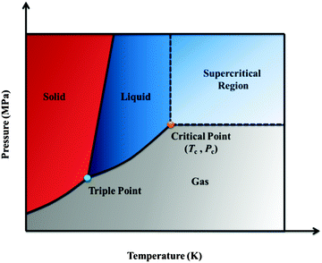
Nanoporous materials represent a new class of materials that have attracted both industrial and academic interest. Polymers with special nanostructures are widely used in gas storage and separation, nanofiltration, sensors, low-dielectric materials, photonic crystals, anti-reflection coatings, and masks for nanopatterning or lithography, owing to their convenient fabrication, synthetic accessibility and easy functionalization. Such unique characteristics and versatile applications of organic polymers are generally unavailable for their inorganic cousins. Moreover, foams account for less material waste and energy expenditure incurred during processing and after disposal, both of which constitute important considerations from an environmental standpoint. In the past decades, a variety of methodologies have been developed to control the porosity, pore shape and size of nanoporous polymer materials, including hard/soft template, self-assembly, and high internal phase emulsion (HIPE) polymerization.1 In particular, block copolymers (BCPs) have predictable self-assembly morphologies in nanoscales. Therefore, strategies for the formation of nanoporous polymeric materials based on the BCP templates have been well-established by Nakahama, Russell, Thomas, Lodge, Hillmyer et al., and were summarized in a review article.2 A typical example was found for the polystyrene-block-poly(methyl methacrylate) (PSPMMA) films annealed under an applied electric field, causing the cylindrical microdomains of PMMA to orient parallel to the field lines.3 After deep ultraviolet exposure, PMMA domains were degraded and simultaneously the PS matrix was cross-linked, successfully resulting in ultrahigh-density arrays of nanopores with high aspect ratios. The obtained nanoporous PS films were subsequently used as templates to fabricate vertical arrays of nanowires with densities in excess of 1.9 × 10¹¹ wires per square centimetre. The essential part of these methods is selective removal of minority domains or templates by chemical, heat, ozone, or UV treatment. However, the harsh removal conditions, such as strong oxidation or high temperature, may limit the applicability of these methods. Additionally, the residual decomposed fragments or templates in the materials may cause secondary contamination in the subsequent biological and microelectronic applications. Therefore, a non-destructive process without residues is more desired from both scientific and practical viewpoints.The supercritical fluid (SCF) technique has been demonstrated as a green and effective means in polymer synthesis and processing.4 An SCF is defined as the state of an element, compound or mixture above its critical temperature (Tc) and critical pressure (Pc). The critical point represents the highest temperature and pressure at which distinct liquid and gas phases exist. The phenomenon can be easily explained with reference to the phase diagram, as shown in Fig. 1. SCF can effuse through solids like a gas, and dissolve substances like a liquid. In addition, near the critical point, small changes in pressure or temperature result in large changes in density, allowing many properties of an SCF to be “fine-tuned”.
Among the substances used as SCFs, CO2 is the most applicable due to its inexpensive, nontoxic and nonflammable characteristics with relatively low Tc and Pc (Tc = 31.3 °C, Pc = 7.39 MPa). Supercritical CO2 (scCO2) shows high diffusivity, “zero” surface tension, and excellent wettability. Moreover, the density of scCO2, as well as its solubility, diffusivity and viscosity, can be easily tuned by adjusting temperature and pressure. Therefore, scCO2 has been widely used to prepare porous polymer films and monoliths with pore size in a very broad range (from several nanometers to hundreds of micrometers). scCO2 foaming is the most used process, by which many microcellular polymer foams with high porosity and cell density have been prepared, such as poly(vinylidene fluoride) (PVDF), PMMA, poly(D,L-lactide) (PLA) and their blends. scCO2 emulsion templates and scCO2 antisolvent induced phase separation are the other alternatives. Compared with other preparation methods, scCO2 processing shows obvious advantages: (1) lots of organic solvents are saved, which is beneficial for environmental protection and energy conservation; (2) removal of scCO2 from porous polymers is spontaneous as CO2 is gaseous under ambient conditions, avoiding the complex steps of removing templates; (3) the obtained porous polymers can be applied in biomedicine and microelectronics, as their formation process is nontoxic.5
Although scCO2 has so many advantages as mentioned above, its lack of polarity leads to a weak ability to dissolve most polar substances. To overcome this limitation, the techniques of CO2-expanded liquids (CXLs) have been developed. A CXL is a mixed solvent composed of compressible CO2 dissolved in an organic solvent.6 By increasing the CO2 pressure, properties of CXLs change from a pure organic solvent to scCO2. A variety of organic solvents can be used to generate CXLs, such as alcohol, acetone, acetonitrile, and so on. Similar to scCO2, CXLs can also be used as special solvents in extraction, crystallization, impregnation, drying, reaction, foaming, etc. In addition to their environmental advantages due to the substantial replacement of organic solvents with environmentally benign dense-phase CO2, CXLs also show several advantages from the point of view of processing conditions (e.g., milder process pressures compared with scCO2, from tens of bars to hundreds of bars) and reaction rates (enhanced transport rates due to the properties of dense CO2, between 1 and 2 orders of magnitude greater than in neat organic solvents or scCO2).
For these unique properties, scCO2 and CXLs have been shown to be “green” porogens for the fabrication of porous polymers. They can provide precise control of foaming processes without residues and extra drying steps. Herein, this tutorial review specifically focuses on the recent advances in the fabrication of nanostructured polymers promoted by newly developed supercritical techniques and materials. In particular, the aim is to highlight areas where the unique properties of scCO2 and CXL foaming can be exploited to generate materials that would be difficult to obtain by other routes. Some important applications of the resultant nanostructures, especially in templates, antireflection coatings, low-k materials, tissue engineering scaffolds and filtration, are reviewed. Furthermore, the methods commonly used to characterize the polymeric nanoporous materials, including a combination of in situ and ex situ measurements, are also summarized. Finally, the challenges and opportunities of this field are discussed.
2 Preparation of nanoporous polymers using scCO2 and CXLs
Usually, the conventional scCO2 foaming process with polymeric materials only produces microscale pores, because the nuclei of CO2 in polymers are thermodynamically determined. In this section, several new foaming techniques with scCO2 and CXLs to introduce smaller structures into polymers are comprehensively summarized and discussed. In particular, the selectively swelling methodology to introduce nanostructures into BCPs is highlighted thanks to the rapid development of BCP theories and controlled living polymerization techniques.2.1 Plasticization of polymers with scCO2
Solubility of a polymer in scCO2 plays a very important role in its foaming process. Generally, the solubility of most polymers in scCO2, except for amorphous fluoropolymers and siloxane-based polymers, is extremely low.7 However, scCO2 can be substantially dissolved in many polymers. In other words, most polymers can be significantly swollen by scCO2 even at modest pressures, leading to a dramatic decrease in their glass transition temperature (Tg) (plasticization). For example, the Tg of polystyrene (PS) can be reduced to 30 °C by scCO2 under the pressure of 25 MPa.2.2 Modified scCO2 foaming process
The pressure-quench method is the primary strategy for generating microcellular polymeric foams.8 As shown in Fig. 2a, a polymer specimen is first plasticized and saturated with CO2 at an elevated temperature in a high pressure vessel. Foaming occurs upon depressurization. Solubility of CO2 in the polymers decreases with decreasing pressure, and then the oversaturated CO2 nucleates and grows as bubbles in the CO2-plasticized polymer specimen, forming cellular or porous structures. Foam growth stops when the Tg of the polymer–CO2 mixture becomes higher than the system temperature and the polymer subsequently vitrifies. The nuclei of CO2 in polymers (both homogeneous and heterogeneous nucleation) generally have a minimum diameter which is thermodynamically determined. Eventually, the resultant pore size is on the order of 10 μm or more, and the number density is small, e.g., 1010 cells per cm3. Moreover, the conventional scCO2 foaming process always results in a dense unfoamed skin as thick as dozens of micrometres, as shown in Fig. 2b, because CO2 near the surface escapes from the polymer specimen prior to the foaming step. Consequently, the unfoamed skin significantly decreases the overall porosity of the thin film. Therefore, the key step for reducing the pore size and increasing porosity is to increase the nucleation rate and decrease the escape rate of CO2.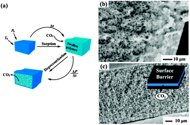 | ||
| Fig. 2 (a) Schematic illustration of the pressure-quench foaming process with scCO2. P0 and T0 indicate the ambient pressure and temperature, respectively.8 Cross-section views of PMMA films foamed at the same pressure and temperature (b) without and (c) with surface constraints. The inset in (c) is the schematic diagram of the surface constrained foam process.9 Adapted with permission from ref. 8 and 9. Copyright 2008 The Royal Society of Chemistry and 2004 American Chemical Society. | ||
Accordingly, Siripurapu et al. developed a surface-constrained process to generate polymer foam with smaller pore cell size and larger pore cell density.9 A PMMA film with a thickness of 100 μm was tightly sandwiched between two smooth stainless steel plates. In this reverse-barrier configuration, CO2 could only escape from the film edges during depressurization, which was expected to increase the residence time of CO2 in the film, eliminating property and morphology gradients along the normal direction of the surface. Finally, nanoporous foams with cells on the order of 100–300 nm were routinely achieved. Thinner films resulted in a cell size of less than 100 nm. An increase in cell density and a reduction in cell diameter were observed with the increase of saturation pressure, exposure time, and depressurization rate, as well as with a decrease in temperature. The surface-constrained foam had excellent cell uniformity, and the unfoamed skin was thin, as highlighted in Fig. 2c.
The same process was applied to poly(ferrocenylmethylphenylsilane) (PFMPS) and poly(ferrocenylmethyl(phenylacetylido)silane) (PFMPAS), which could serve as precursors for magnetically and electrically active ceramics.10 It was revealed that foams with submicron cells could be generated by the judicious selection of exposure pressure and temperature. The variation in the chemical constitution between the PFMPS and PFMPAS appeared to have little effect on the foam morphologies and formation processes. At the same time, curvature of the films and non-negligible surface roughness created paths that facilitated CO2 diffusion, resulting in elongated pores that were either normal or oriented at approximately 30° to the film surface. These studies were helpful for the fabrication of magnetically and electrically active porous ceramics from the foamed poly(ferrocenylsilane) (PFS) homopolymers.
Another effective method to reduce the pore size and increase the pore density is to use additives. Hard (inorganic filler) or soft (polymer surfactant) additives in the polymer matrix can increase internal diffusion barriers of CO2 bubbles by creating more tortuous diffusive pathways, and simultaneously can induce heterogeneous nucleation on the surface of the dispersed nanoparticles or in pre-existing microvoids. Inorganic fillers such as silica nanoparticles and organically modified clay have received substantial attention as nucleating agents to enhance nucleation rate, reduce pore size, and increase pore density. Zhai et al. systemically investigated the influence of silica nanoparticle additives on the formation of submicron pores in a melt-processed polycarbonate (PC).11 Compared with neat PC, PC–nanosilica nanocomposites (PCSN) had uniform distribution of cell size with an average value of 300–500 nm and an increased cell density of 1011–1013 cells per cm3 under the same foaming conditions, as shown in Fig. 3a and b. An increase in the saturation pressure tended to narrow the cell size distribution and increase the cell density of PCSN foams, because the high CO2 concentration at high saturation pressure shortened the nucleation time. In addition, the foaming temperature did not affect the cell density of PCSN foams due to the dominant heterogeneous nucleation. For the same reason, a remarkable increase of cell density and decrease of cell size with increasing nanosilica content were observed. Zeng et al. employed chemically modified clay to assist the formation of nanostructures in PS and PMMA by the scCO2 foaming process.12 A small amount of clay nanoparticles greatly reduced the cell size and increased the cell density. After saturation at 0 °C and 3.45 MPa and foaming at 80 °C for 15 s, the resulting PMMA foam with 5 wt% clay showed an average cell size around 300 nm and a cell density around 1.86 × 10¹² cells per cm3.
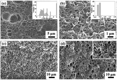 | ||
| Fig. 3 SEM images of polymers and polymers with additives: (a) neat PC and (b) PCSN (with 9 wt% silica nanoparticles) foams; the insets are the pore size distribution.10 (c) PMMA and (d) PMMA with 2 wt% poly(methyl methacrylate)-block-poly(dihydroperfluorooctyl methacrylate) (PMMA-b-PFOMA) foams; the inset in (d) is 5× enlargement.13 Reproduced with permission from ref. 10 and 13. Copyright 2006 Elsevier Ltd. and 2005 American Chemical Society. | ||
Soft additives of oligomeric surfactants and fluorinated block/graft copolymers were also used to reduce the pore size and to increase the pore density.13 The oligomeric surfactants containing CO2-philic moieties had little effect on foaming PMMA over a large concentration range, whereas the copolymers containing CO2-philic blocks and grafts at concentrations above the critical micelle concentration (cmc) in PMMA served to increase the pore cell density over all pressures and temperatures, as shown in Fig. 3c and d. The porous polymer films with very thin dense skin layers and a pore size of 100–300 nm could be obtained. Macromolecular additives either dispersed molecularly or formed micelles in the polymer matrix during specimen preparation. When a homopolymer/copolymer film was saturated with CO2 for an extended period of time at temperatures above the Tg of the CO2-plasticized polymer matrix, the copolymer could diffuse through the polymer matrix and, at concentrations above the cmc, self-organize into thermodynamically stable CO2-swollen micelles, wherein the CO2-philic moieties served to entrap CO2 molecules. These micelles also served as heterogeneous nucleation sites during depressurization.
Another strategy for generating nanopores in the polymer matrix is the temperature-soak method. A polymer is saturated with scCO2 at a temperature below the polymer–gas Tg in a high-pressure vessel. The vessel is subsequently depressurized and the sample is taken out from the vessel quickly and immersed into a liquid bath with a temperature above the polymer–gas Tg. Bubbles nucleate and grow until the sample is removed from the heat source. Vegt et al. investigated the formation of open nanoporous films with a series of high-Tg polymers of polysulfone, polyimide (PI) and their derivates by this method.14 Foaming only took place in the temperature range between the Tg of the polymer–CO2 mixture (Tlower) and an upper bound temperature (Tupper). For both poly(ether imide) (PEI) and poly(ether sulfone), closed microcellular structures were obtained at CO2 saturation levels below 50 cm3 (STP) per cm3 (Fig. 4a and b)15 and nanoporous bicontinuous (open) structures with a pore size as small as 40 nm were prepared above this CO2 concentration threshold (Fig. 4c). Moreover, molecular orientation in rigid PI allowed one to manipulate the evolution of the foam morphology from spherical to lamellar structure with an interlayer distance of less than 100 nm (Fig. 4d).16 It is foreseen that polymers which tend to self-organize into aligned mesoscopic structures, such as main-chain or side-chain liquid crystalline polymers, may boost the porosity to an even higher value.
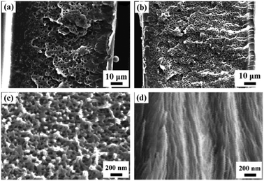 | ||
| Fig. 4 SEM images of the PEI film saturated at (a) 10 bar; (b) 30 bar; (c) 50 bar of CO2 and foamed at 180 °C. (d) Kapton HN with a sheet-like structure foamed at 300 °C.15,16 Reproduced with permission from ref. 15 and 16. Copyright 2001 American Chemical Society and 2002 WILEY-VCH Verlag GmbH & Co. KGaA, Weinheim. | ||
2.3 scCO2 and CXLs selectively swelling BCP templates
BCPs are macromolecules composed of linear or nonlinear arrangements of chemically different polymeric chains. Depending on the chemical immiscibility and the volume fractions of the composed blocks, BCPs can self-assemble into a variety of thermodynamically stable, ordered structures in the nanoscale. For diblock copolymers, they can form various equilibrium microphase morphologies of spheres (S), cylinders (C or Hex), double gyroid (G or Gyr), lamellae (L or Lam), and their inverse structures (as shown in Fig. 5), basically depending on both the volume fractions of the two blocks and the chain architectures.17 BCP self-assembly typically yields materials with microdomain structures ranging from 5 to 50 nm. Therefore, they are believed to be the ideal templates for the fabrication of nanoporous materials. The often-used technique is to selectively remove the minority component by etching techniques, whereas the remaining matrix must be able to support the porous structure. Evidently, only cylindrical and gyroid structures are suitable for the selectively decomposing strategy. When the microphase morphology is a discrete spherical domain structure, full degradation of the minority block is difficult to achieve, because there are no paths through which the decomposed fragments can escape. Therefore, closed nanostructures are difficult to be achieved by the selectively decomposing strategy. Watkins et al. prepared silicate films with closed nanopores by impregnating tetraethyl orthosilicate (TEOS) into poly(ethylene oxide)-block-poly(propylene oxide)-block-poly(ethylene oxide) (PEO-b-PPO-b-PEO) templates.18 A catalyst of organic acid was initially added and selectively partitioned into the hydrophilic matrix of PEO. Through swelling the films with a dilute solution of TEOS in scCO2, TEOS was infused and enriched within the domain of PEO. After removing the BCP templates by calcination, mesoporous silicates were produced. | ||
| Fig. 5 Morphologies formed by diblock copolymers containing two incompatible blocks. The exact formed structure depends on the volume fractions of the two blocks (composition ratio) and their level of incompatibility.17 Reproduced with permission from ref. 17. Copyright 2008 American Institute of Physics. | ||
scCO2 selectively swelling methodology is much more impressive for the formation of nanoporous polymers, because it is mild, non-destructive, and able to produce diverse morphologies. The typical polymer nanostructures and their formation process are schematically summarized and shown in Fig. 6.19–22 For the preparation of closed nanocellular structures, a fluorinated diblock copolymer, polystyrene-block-poly(perfluorooctylethyl methacrylate) (PSPFMA), was cast with a PS-selective mixed solvent (e.g., toluene and 1,1,1,3,3,3-hexafluoro-2-propanol). Because of the selectivity of the casting solvent and the strong repulsive interaction between PS and PFMA blocks, spherical PFMA nanodomains separated in the continuous PS matrix in the as-cast films (Fig. 6a and b). Nanocells were introduced into the films by the following protocols: (1) A specimen was placed in a high-pressure vessel with a CO2 pressure in the range of 7.5–30 MPa at 60 °C for 1 h; (2) the temperature was reduced to 0 °C while maintaining the CO2 pressure; (3) the CO2 in the vessel was released at a fixed rate. In this method, the CO2-philic PFMA nanodomains served as templates to localize and stabilize significant amounts of CO2 thanks to the high affinity of the fluorinated block to CO2. Eventually, empty nanocells surrounded by the PFMA composition formed after depressurization within the skeleton of the PS domain. It should be noted that neither cells nor pores were introduced into homoPS by the same CO2 processing. Temperature of depressurization (Td) must be well below the Tg of the skeleton PS domains in the presence of CO2; otherwise, the size of formed cellular structures would be on the order of micrometers, which was the typical cell structure formed following the conventional foaming mechanism. Thus a combination of the use of fluorinated BCP templates and the protocol of the CO2 process is the key to the successful fabrication of nanocellular monoliths. The embedded nanocellular structures were revealed by cryo-fracture and characterized using a scanning electron microscope (SEM). The density of the resultant nanocells was in the range of 1 to 5 × 10¹⁶ cells per cm3. Surprisingly, the thickness of the skin layer was only 15 nm, a few orders of magnitude thinner than the conventional skin layer. The thin skin layer could be contributed to the PFMA layer that distributes on the polymer surface to reduce the total free energy of the system. In such a segregated planar layer, foaming of CO2 was impossible. Accordingly, a new foaming mechanism different from the mentioned temperature-soak and pressure-quench strategies is developed. This strategy can be further applied to the preparation of nanoporous super-thin films. A maximum porosity of 50% could be achieved in the thin film with a thickness less than 100 nm at 25 MPa of saturation pressure. Cross-sectional views indicated that a single layer of closed cellular structure with a number density of 8.3 × 10¹⁰ cells per cm2 and diameter of 20 nm was formed in the PSPFMA film with a thickness of 47 nm (Fig. 6b).19 Such thin polymer films are expected to function as ideal masks for nanolithography.
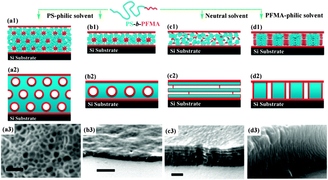 | ||
| Fig. 6 Schematic diagrams of the morphologies of the as-cast films (line 1) and foamed films by the selectively swelling process with scCO2 (line 2). Depending on the casting solvents, the same BCP shows different initial morphologies in the as-cast films. Line 3: the SEM images of the resultant nanoporous structures after the same CO2 process; closed nanopores (a) in the bulk and (b) in the film, scale bars are 100 nm and 200 nm, respectively; nanosheets (c) horizontal and (d) vertical to the substrate, scale bar indicates 100 nm.19,21,22 Adapted with permission from ref. 19, 21 and 22. Copyright 2006, 2008 American Chemical Society and 2004 WILEY-VCH Verlag GmbH & Co. KGaA, Weinheim. | ||
By simply changing the selectivity of casting solvent for the PFMA composition, completely different initial morphologies were formed in the as-cast films.21 The PSPFMA films prepared from trifluorotoluene (TFT, a neutral solvent) showed network-like domains of PFMA (red) with many defects without specific symmetry (Fig. 6c). On the other hand, when hexafluorobenzene (HFB, a selective solvent for PFMA) was used, it was observed that thin walls of the PFMA domains separated relatively large circular PS domains, as shown in Fig. 6d. Starting from these films with different initial morphologies, horizontally or vertically aligned polymer nanosheets appeared after the same CO2 processing protocol.
It is worth noting that all the obtained nanostructures fabricated with the scCO2 process are different from the as-cast morphologies, even for the closed nanocellular structures. The reason may be that selectively swelling the minority PFMA domains with scCO2 increases their effective volume fraction, inducing structure reconstruction and phase transition. Because the diffusion process of BCPs is controlled by a thermodynamic barrier of the activated hopping of an individual BCP chain, complete shape transformation may not be accessible on an experimental time scale.23 Therefore, the resultant nanostructures are still in a “thermodynamically restricted” nonequilibrium state, and they are strongly dependent on the initial as-cast morphologies and processing conditions, such as saturation pressure and temperature. Thus it is difficult to precisely predict the behaviour of this system. However, a nonequilibrium state can be advantageous, for it provides us with the possibility of constructing structures that are not available in an equilibrium state by simply adjusting the processing conditions. The scCO2 selectively swelling process was also employed to introduce pores into other BCPs. A semi-fluorinated BCP with high Tg, poly[4-(1-adamantyl)styrene]-block-poly(perfluorooctylethyl methacrylate) [P(AdSt-FMA)], was used as a template to prepare thermally robust nanocellular thin films, following the same procedure as described above.24 The average diameter of the pores was about 20 nm. Owing to the bulky adamantyl group, PAdSt had a Tg close to 250 °C, and the nanocellular copolymer films had remarkable thermal robustness up to more than 200 °C.
Siloxane-based polymers are another type of polymer which can be selectively swollen by scCO2. Similarly, nanoporous structure was introduced into a polystyrene-block-poly(dimethylsiloxane) copolymer (PSPDMS) film by the scCO2 selectively swelling process.25 This nanoporous film was then oxidized by exposing it to UV light/ozone to decompose the PS blocks and to convert the PDMS blocks into silica. Consequently, silica “nanocapsules” were obtained, with a diameter less than 40 nm and a wall thickness of 2 nm. The top half of these nanocapsules was subsequently removed by reactive ion etching (RIE) techniques, forming the “nanocalderas”. Fabrication of these types of inorganic nanostructures is difficult using conventional techniques.
The successful preparation of nanostructured polymers with selectively swelling methodology is strongly dependent on the existence of CO2-philic blocks in BCP. However, CO2-philic monomers available now are limited to siloxanes and fluorous compounds, which restricts the further applications of this method. In order to circumvent the dilemma, two strategies are developed. One is to design and synthesize new CO2-philic monomers. It has been reported that carbonate-containing oligomers have a high solubility in scCO2.26 So new BCPs containing carbonate composition and their nanoporous materials are promising. Another strategy is to improve the polarity and dissolving capacity of scCO2 by adding organic solvents. As a modal, an amphiphilic BCP, polystyrene-block-poly(vinylpyridine) (PSPVP), was treated with the scCO2–methanol binary system. Zhang et al. introduced closed nanocellular structures into PSPVP thin films at relatively low pressure and temperature (2–6 MPa and 25 °C).27 In this study, CO2 and methanol always showed two-phase co-existence under the employed pressure and temperature. The polymer films were submerged in the liquid phase (methanol) during the process. Methanol selectively swelled the domains of PVP, while CO2 plasticized the PS domains, both of which were the key to generating nanopores in the films after depressurization. Eventually, cellular pores with diameter ranging from 20 to 70 nm were formed, depending on the saturation pressure. Recently, our group demonstrated the formation of nanonetworks with the same amphiphilic diblock copolymer at high pressure and temperature (12–20 MPa and 45 °C).28 The calculated phase diagram of the CO2–methanol binary system at 45 °C is shown in Fig. 7a. Accordingly, the foaming saturated pressure of 12–20 MPa fell in the range of homogeneous phase. The foaming procedure was the same as the above-mentioned selectively swelling protocol. Using BCP with spherical PVP dispersed in the continuous PS matrix as templates, interconnected networks were formed after the CXL process, as shown in Fig. 7b and c. The adsorption technique was used to confirm the interconnected structures. On the experimental pressure scale, a maximum BET surface area of 103.9 m2 g−1 was achieved. In order to introduce nanostructures into BCPs, the key step was to effectively plasticize the surrounding matrix and selectively swell the minority compositions followed by fixing the morphology at a low temperature. During CXL treatment, the CO2–methanol system not only dramatically plasticized the PS matrix, but also increased the effective volume fraction of PVP domains, because of the selectivity of methanol toward PVP segments. It was believed that the continuous increase of the effective volume fraction of PVP domains eventually induced the morphological transition to network structure. In the subsequent isobaric quenching, the homogeneous CO2–methanol system turned into two phases, according to the state equation. The specimens soaked in methanol could not be further swollen, and then the formed nano-structures were fixed.
 | ||
| Fig. 7 (a) P–x–y diagram of the CO2–methanol system at 45 °C; the critical point is marked with ‘c’ (P = 10.8 MPa, x1 = 0.882). (b) Top and (c) cross-sectional views of PSPVP films after the CO2–methanol process show a network structure. The inset in (c) is a magnified cross-sectional view.28 Reproduced from ref. 28 with permission from The Royal Society of Chemistry. | ||
Based on the mechanism of the selectively swelling strategy, neat organic solvents have also been exploited to produce BCP nanoporous films. Wang et al. prepared bicontinuous nanoporous structures by soaking PSPVP in ethanol or acetic acid at 60 °C.29 The pore size ranged from 25 nm to 40 nm, depending on the soaking time. Although a high pressure vessel is not needed in the soaking process, the pore formation took several hours and the collapse of the nanostructures should be carefully avoided since extra drying is necessary.
2.4 scCO2 and CXLs induced phase inversion
Phase inversion is the most used technique for preparing porous polymer membranes. When a homogeneous polymer solution comes in contact with a nonsolvent of the polymer (miscible with the original solvent), the diffusion of the nonsolvent will cause thermodynamic instability of the homogeneous solution and lead to solidification of the polymer-rich phase, yielding several different possible structures.30 By selecting proper conditions, such as polymer concentration, solvent and temperature, micrometric open pore structures can be obtained. The phase inversion technique is simple, but its limitations are also obvious: narrow selection of nonsolvents, and long processing time, due to complicated post-treatments of washing and drying the membranes.scCO2 is a suitable candidate for nonsolvent in the phase inversion process, because it is miscible with a number of organic solvents and most polymers are insoluble in it. Importantly, scCO2 can quickly diffuse into a polymer solution, and after phase inversion it escapes from the polymer membrane rapidly and completely without the need of additional post-treatment. At the same time, the solvent dissolved in scCO2 can be easily separated from gaseous CO2 after depressurization and collected.
Barroso et al. polymerized methyl methacrylate (MMA) and methacrylic acid (MAA) in scCO2.31 These copolymers were then used to prepare thin pH-responsive membranes by the phase inversion method with scCO2 as a nonsolvent. It was found that increasing the copolymer concentration led to a more homogeneous cellular structure with top and bottom surfaces covered by a continuous layer. The porosity decreased with increasing copolymer concentration. The mean diameter reduced from about 21 μm at 20% (w/w) to 400 nm at 40% (w/w). The resulting cellular morphology indicated that liquid–fluid demixing was the controlling mechanism under the experimental conditions.
Reverchon and Cardea investigated the preparation of porous membranes of copolymer of vinylidene fluoride and hexafluoropropylene (PVDF–HFP) by a similar method.32 A series of experiments were performed at various polymer concentrations, temperatures, and pressures using acetone as the liquid solvent. Depending on the process conditions, two kinds of morphologies could be obtained, cellular structure with a diameter of 2–6 μm and bicontinuous structure with submicron pores. In both cases, a leafy-like morphology was observed. By increasing the pressure and decreasing the temperature, the membrane morphology changed from cellular to bicontinuous structures. The structural evolution might be the result of the competition between liquid–liquid and solid–liquid demixing, which led to the cellular and bicontinuous structures, respectively.
The major drawback of scCO2 as nonsolvent is the very low affinity between CO2 and water under the ordinary process conditions. As a consequence, this process cannot be used to produce membranes of water-soluble polymers (e.g., the majority of biopolymers). To overcome this limitation, Reverchon and Cardea proposed using CO2-expanded ethanol as the nonsolvent in the phase inversion process.33 With this CXL assisted phase inversion method, they successfully prepared porous polyvinyl alcohol (PVA) membranes with open cellular structures, a cell size ranging between 0.5 and 4 μm and a dense or porous skin.
3 Characterization of nanoporous polymeric materials
The investigation of nanoporous materials has highly relied on the improvement of characterization techniques, involving the fundamental elucidation of phase behaviour, and identification of the unique nanostructures that make them ‘fit for functions’ in the applications. The main subject of this section is to describe and analyse the newly developed non-destructive techniques suitable for determining the critical properties of these nanoporous materials, including morphology, pore size, surface area and porosity.3.1 Imaging techniques
Imaging techniques, including optical and electronic imaging, are used to determine the size, shape, and connectivity of pores through direct visualization over various length scales, from angstroms to microns. When used in conjunction with indirect methods, imaging is a powerful complement to construct real structural models for porous morphologies.SEM images are based on the contrast of topography and chemical composition. The incident electrons interact with atoms at the surface of the sample, and produce various second electrons (SEs) and backscattered electrons (BSEs), which contain information about the sample's surface topography and chemical composition, respectively. SEs are ejected from the k-shell of the specimen atoms by inelastic scattering interactions with incident beam electrons, and the generated images are dominated by topographic features. In a similar way, images from BSEs reflect the distribution of the chemical composition of the sample. An important limitation of SEM observation is that the specimens must be conductive, because nonconductive specimens tend to become charged when scanned by the electron beam, which will cause scanning faults and other image artifacts. Therefore, nonconductive polymeric specimens are usually coated with an ultrathin coating of electrically conductive material to reduce overcharge. However, the coating may obscure the fine features of the sample at very high magnification. To get clear images, these uncoated insulating specimens may be imaged using environmental SEM (ESEM). The primary advantages of ESEM lie in permitting the microscopist to vary the sample environment through a range of pressures, temperatures and gas compositions, which mainly relies on the environmental secondary detector (ESD) that can work in a non-vacuum environment.34 The mechanism of ESD is schematically shown in Fig. 8a. As the SEs are accelerated in the detector field, they collide with gas molecules. The resulting ionizations create additional electrons, not only amplifying original SE signals but also generating positive ions to effectively suppress charging artifacts. Therefore, clearer images can be obtained, as highlighted in Fig. 8b and c.
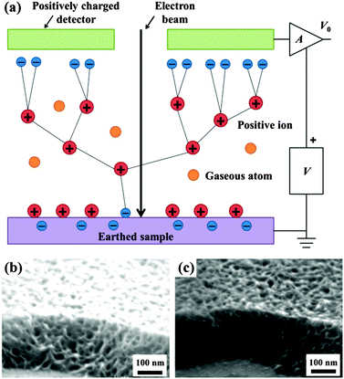 | ||
| Fig. 8 (a) Schematic diagram of the ESEM cascade amplification process.34 Images of the non-conducting nanoporous polymer sample by SEM (b) and ESEM (c). Charging artifacts can be effectively eliminated by ESEM. Adapted with permission from ref. 34. Copyright 2003 Nature Publishing Group. | ||
The transmission electron microscope (TEM) has a similar basic principle as the light microscope but uses an electron beam instead of light. The contrast of TEM images is the result of the strong interaction between the electrons and the specimen as they pass through it. In addition to common two-dimensional (2D) images, TEM can give three-dimensional (3D) nanoscale morphology information of various specimens by the electron tomography technique, which is also referred to as transmission electron microtomography. This technique has been well-established for the study of biological structures.35 More recently, it has been applied to the characterization of nanoporous polymeric systems.36 As shown in Fig. 9a, to obtain a 3D image, electron tomography is first used to take a series of 2D projections at different angles by tilting the specimen with respect to the electron beam in the TEM column. Then, the obtained 2D projections are used to reconstruct a 3D image of the specimen on the basis of computerized tomography, with nanoscale resolution. The resulting 3D image can then be used voxel by voxel to study the specimen's morphological organization in detail. Representative 2D projections and 3D TEM images of a nanofoam are shown in Fig. 9b and c.37
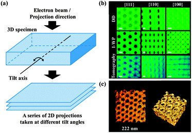 | ||
| Fig. 9 (a) Schematic diagrams of the electron tomography principle; a series of 2D projections taken at different title angles are used to reconstruct the 3D image of the specimen.36 (b) Representative projection images generated from proposed double diamond (DD) and Schoen's I-WP structure models and tomographic reconstruction. Scale bars indicate 20 nm. (c) TEM tomographic reconstruction of the polymer scaffold. The material is shown in bright colours.37 Reproduced with permission from ref. 36 and 37. Copyright 2009 The Royal Society of Chemistry and 2013 American Association for the Advancement of Science. | ||
Micro X-ray computed tomography (microCT), which has been widely used in biology, is another promising technique to provide both 2D and 3D images of porous materials.38 In the imaging process, a collimated X-ray beam with fixed energy is focused onto a sample and the transmitted beam is focused onto a detector. The contrast of the images is determined by the mass absorption coefficient of the components in the sample. By rotating the sample, 3D images are obtained, which can be used to determine the porosity, pore size and interconnectivity of the sample. In contrast to physisorption and porosimetry, microCT can assess both connected and isolated pores. However, the relatively low resolution of microCT (micrometer) has limited its further development and application. With the rapid progress of material science, the improvement of resolution is urgently needed.
3.2 Scattering techniques
One drawback of imaging characterization is that only a very small part of the sample can be investigated. Therefore, other characterization techniques with a macroscopic and statistical approach are needed. For nanoscale structures, small angle X-ray scattering (SAXS) techniques are often utilized. The scattering angle and intensity in SAXS patterns exhibit a contrast of electron density with the surrounding media in the nanometer range, containing information about the shape and characteristic distance of partially ordered materials, such as nanoporous polymeric films and monoliths.Conventional transmission SAXS techniques can be used for bulk specimens. Combined with atomic force microscope (AFM) and SEM, SAXS was used to elucidate the nanocellular structures in PSPFMA, which were formed by selectively swelling the spherical domains of PFMA with scCO2.22 As shown in Fig. 10a, the scattering profile of the original sample had only a broad peak, suggesting a spherical domain structure with a short-range order. After CO2-processing, the SAXS profiles clearly confirmed the presence of nanocells: the first peak shifted to the lower number of wave vector, indicating that the spacing of nanocells was greater than that in the original sample, and that the cells were still in the short-range order. The apparent broad second order peaks were not the higher order diffractions of the lattice, but were likely the form factors of hollow spheres, the spherical empty cells surrounded by the PFMA blocks with a higher electron density, as schematically shown in Fig. 10b. Shinkai et al. used in situ SAXS and ex situ SEM measurements to confirm the appearance of a unique foam structure and pressure-induced order–order transition (OOT) in semifluorinated BCPs at various pressures of scCO2.39 Both PSPFMA and PSPFMA/homoPS blend showed OOT from the as-cast cylinder to lamellae at 10 MPa. As the pressure increased further, neat PSPFMA showed a phase transition from lamellae to a 100 nm-order foam structure instead of the typical inverted phases. In the PSPFMA/homoPS blend, the added homoPS prevented lamellar bilayers from separation. Therefore, phase transition to a sponge-like bicontinuous structure was observed.
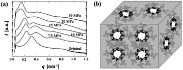 | ||
| Fig. 10 (a) SAXS profiles of nanocellular PSPFMA monoliths processed at various CO2 saturation pressures. (b) A schematic diagram of the expected nanocellular structure. The domains (dark gray regions) of the PFMA blocks (black curves) are surrounding the cells (white regions) while the continuous domain (light gray region) of the PS blocks (gray curves) supports the nanocellular monolith.22 Reproduced with permission from ref. 22. Copyright 2004 WILEY-VCH Verlag GmbH & Co. KGaA, Weinheim. | ||
Grazing incidence SAXS (GISAXS) is based upon the same principles as SAXS. The main difference between SAXS and GISAXS is the incidence angle θ: SAXS uses normal incidence, while GISAXS uses incidence angles close to zero.40 GISAXS is a powerful tool for studying nanostructures in thin films, and it can enable us to separate the form factor from the structure factor and to determine the detailed structures of the nanocells, which cannot be measured using transmission SAXS. Yokoyama et al. analyzed the PSPFMA thin films with a single layer of nanocells by GISAXS under optimized geometry with quantitative calculations using distorted wave Born approximation (DWBA).41 A spherical concentric shell (SCS) model, but not a sphere (S) model, provided a reasonable fit to the GISAXS profile, indicating that the spherical nanocells were surrounded by a thin shell of PFMA in the foamed films (Fig. 11a and b). Therefore, it was revealed that in the foam process, CO2 localized in CO2-philic domains under pressure and produced cells in each spherical CO2-philic domain upon depressurization.
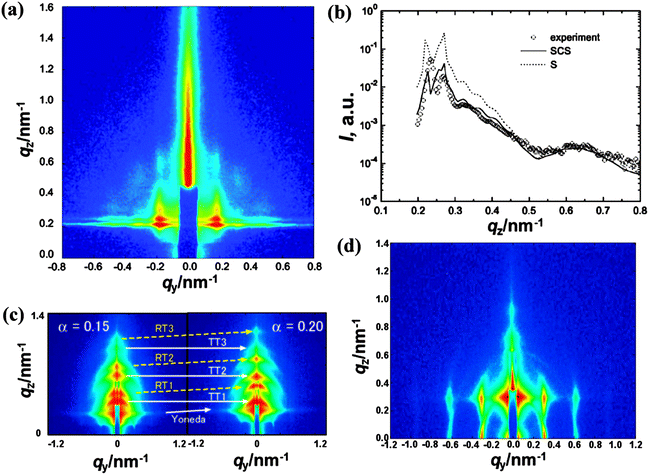 | ||
| Fig. 11 (a) GISAXS pattern of monolayer nanopores in the PSPFMA film; qy and qz are the wave vectors parallel and perpendicular to the film plane, respectively. (b) Plots of intensity vs. qz of the nanocellular thin film at the peak qy, a slice along the z axis of (a), the experimental profile (circle) is fitted with the S model (dotted line) and the SCS model (solid line). The SCS model fits the experimental profile better than the S model. GISAXS patterns of nanosheets (c) parallel and (d) perpendicular to the substrate. The intensity increases from blue to red on a logarithmic scale. T and R in (c) represent transmission and reflection components, respectively.21,41 Reproduced with permission from ref. 21 and 41. Copyright 2008 American Chemical Society and 2007 AIP Publishing LLC. | ||
As shown in Fig. 6c and d, by simply changing the initial morphology in the as-cast films, polymer nanosheets parallel and perpendicular to the substrate were produced after scCO2 foaming. GISAXS patterns shown in Fig. 11c and d not only offer the solid statistical evidence but also facilitate the elucidation of their formation mechanism. For example, the GISAXS intensity of nanosheets was more than an order of magnitude stronger than that of the as-cast films before foaming by scCO2. Therefore, the electron density contrast increased with the voids introduced by the process. In addition, the existence of higher order peaks also indicated that the defect bridge and substrate effect prevented the lamellae from completely collapsing during the depressurization.
3.3 Physisorption and porosimetry
Physisorption techniques are typically employed to measure the surface area, pore size distribution and porosity of nanoporous materials. Usually, the surface area of the materials with micropores and mesopores is calculated using the Brunauer–Emmett–Teller (BET) theory.42 The BET equation can be described as follows:| C = Ae(E1−EL)/RT |
| As = nmNAAm |
Pore volume and pore size distribution are often obtained by calculating each point along the isotherm via the Barrett–Joyner–Halenda (BJH) equation described as follows:43
in which Ap,j = 2Vp,j/rp,j, Vp,n is the pore volume, Δtn the change in the statistical thickness, rp pore radius, and rk the radius of the inner capillary. A typical adsorption–desorption isotherm and the corresponding pore diameter distribution calculated with BJH equation are shown in Fig. 12. However, the BJH method is sometimes imprecise because a simplified macroscopic explanation of the capillary condensation is effective with limitations at the microscopic level. Therefore, a new method based on the nonlocal density functional theory (DFT) has been proposed to calculate the pore size distribution of porous materials.44
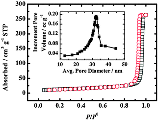 | ||
| Fig. 12 N2 adsorption (squares)–desorption (circles) isotherms of a PSPVP film. The BET surface area is 103.9 m2 g−1. The BJH average pore diameter is 31 nm (inset).28 Reproduced from ref. 28 with permission from The Royal Society of Chemistry. | ||
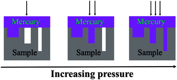
The adsorption method is suitable for characterizing materials containing micropores and mesopores. For materials with macropores, porosimetry is a better technique to determine the porosity and pore size distribution. The porosimetry technique is based on the capillary law that describes the liquid penetration into small pores. The pressure required to intrude the non-wetting liquid (often mercury) into the pores is inversely proportional to the size of the pores, which has been expressed as the well-known Washburn's equation:45
The selection of both theoretical model (e.g., identification of pore shape) and experimental condition has a significant effect on the measured values of porosity and pore size. Therefore, in order to get accurate pore size and porosity, the correct evaluation of the morphology of the sample as well as determination of proper experimental conditions is critical. This can be accomplished with the assistance of other methods, such as SEM and SAXS. Additionally, it should be noted that the adsorption method and porosimetry can be used only to characterize materials with open pores. Those materials with closed pores, which are not accessible to gas molecules or liquids, cannot be analysed by the adsorption method or porosimetry.
4 Applications of nanoporous polymers
The formation of nanostructured polymers with scCO2 and CXLs does not need chemical treatment and toxic organic solvents. Therefore, secondary pollution is avoided in the following biological and microelectronic applications. In this part, we summarize their practical applications in templates, optical devices, low-k materials, biotechnology and filtration.4.1 Template application
Nanoscale structures with a controlled size can directly serve as templates to prepare other more functional nanodevices. Our group prepared a variety of polymeric films with nanoscale networks by selectively swelling PSPVP with CXL.28 Using the nanoporous polymer films as templates, polypyrrole (PPy) films with different porosity and pore size were prepared by electrochemical polymerization. After removal of the polymer templates by soaking them in THF, porous PPy films were left, as shown in Fig. 14a. When the PPy film was used as a sensing element in a gas sensor, the porous structure could significantly improve the sensing performance, owing to the large surface area and the interconnected channels for rapid gas diffusion. As shown in Fig. 14b, when exposed to ammonia, the sensor with porous PPy films as sensing elements showed a signal 10 times stronger than that based on compact PPy films. Similarly, this polymer template can be used to fabricate other porous materials, such as porous platinum, which has potential application in catalysis.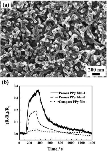 | ||
| Fig. 14 (a) SEM image of a PPy replica of the nanoporous PSPVP film obtained by a CXL process. (b) Ammonia gas sensing performance of porous PPy films duplicated from PSPVP networks with pore size of 31 nm (film-1) and 68 nm (film-2) and a compact PPy film without pores.28 Reproduced from ref. 28 with permission from The Royal Society of Chemistry. | ||
Another template application of polymeric nanonetworks is to control crystallization. Up to now, reliable protocols for controlling crystallization and crystal properties, particularly polymorphism, have remained a central challenge. Hillmyer et al. compared the crystallization behaviour of anthranilic acid in nanoporous polymer and glass matrices, and revealed the evident influence of pore confinement on polymorph discrimination.46 The nanoporous polymer monoliths are particularly interesting, because the polymer matrix can be fractured or dissolved to release polymorph seeds, which may be difficult to generate when other inorganic templates are used. The ability to achieve polymorph selectivity in polymer matrices suggests wide-ranging compatibility with various organic crystalline solids. scCO2 and CXL processes have proved to be versatile techniques for the preparation of polymeric porous structures without secondary contamination. Therefore, we expect that more amphiphilic BCPs with different chemical compatibilities can be exploited, to produce various polymeric nanostructures by the scCO2 and CXL techniques, which can be used to control polymorphism and to search for unknown polymorphs.
scCO2 can also be directly used as a template to prepare porous materials. Cooper et al. used scCO2 HIPEs in water as templates to produce highly porous polymers.47 A pore volume as high as 5.89 cm3 g−1 can be achieved. The viscosity of the aqueous phase is the key effect factor in the formation of CO2 HIPEs. Compared to other oil in water (O/W) template techniques, this new method avoids any volatile organic solvent in both the synthesis and purification processes. Simultaneously, it overcomes the difficult problem of removing the template from the materials at the end of the reaction. Although only microscale pores are currently obtained by the CO2 HIPE template, it is believed that nanopores can be prepared with the development of HIPE techniques in the near future. Zhang et al. further explored the template application of scCO2 in ionic liquid (IL) microemulsions for fabrication of metal–organic frameworks (MOFs), as shown in Fig. 15.48 In a scCO2–fluorinated surfactant–IL ternary system, fluorinated surfactant micelles were swollen by scCO2, and the precursor of MOF was incorporated in the continuous phase of the microemulsion. Therefore, the micelles acted as templates for the pores in MOFs. Moreover, the high viscosity of IL could trap some IL–scCO2 solution during the formation of the MOF, leaving the smaller pores after the IL and CO2 were removed. Eventually, MOFs with hierarchical porous structures were formed. The mesopores in the range 20–50 nm corresponded with the micellar size of the scCO2-in-IL microemulsions.
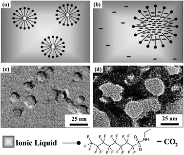 | ||
| Fig. 15 Schematic illustration of “dry” micelles dispersed in (a) IL and (b) CO2-in-IL microemulsion. TEM images of (c) “dry” micelles and (d) hierarchical porous MOF synthesized in CO2-in-IL microemulsion.48 Adapted with permission from ref. 48. Copyright 2011 WILEY-VCH Verlag GmbH & Co. KGaA, Weinheim. | ||
4.2 Antireflection coating
Antireflection (AR) coatings are used to maximize the transmission of light through optical surfaces and to achieve high contrast and brightness in display devices, which are needed for photovoltaic devices and all kinds of optical lenses. The principle of AR is to produce the destructive interference between the reflected light from the air–coating and coating–substrate interfaces according to the Fresnel Law, as shown in Fig. 16a. An ideal homogeneous AR coating should satisfy the following conditions: the thickness of the coating should be λ/4, where λ is the wavelength of the incident light; and , where nc, na, and ns are the refractive indices of the coating, air, and substrate, respectively.
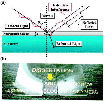 | ||
| Fig. 16 (a) Schematic illustration of Fresnel Law. (b) Display effects of the glass slides with (the middle) and without (the left, the right) an AR layer. | ||
Compared with inorganic materials, polymeric materials have great practical value and wide applications in AR coatings, because they possess the ability to adhere to the flexible substrate and the advantage of easy large-area processing. Nanoporous polymer films produced by the scCO2 selectively swelling process are ideal candidates for AR coatings. The introduced pores have a size less than 50 nm. Therefore, the nanoporous polymer film is transparent to visible light (400–700 nm wavelength). In addition, the embedded nanocells not only significantly reduce the reflective index but also effectively dissipate energy and delay the crack propagation with a minimum impact on the Young's modulus of the polymer film.49 Accordingly, a nanoporous thin film with a refractive index of 1.24 (equivalent to 50 vol% of porosity) and a thickness of 125 nm (1/4 wavelength of red light) was prepared on a glass substrate. Under sunlight, glass substrates without the AR film reflected all the visible light with various wavelengths, so they appear opaque (the left and the right side in Fig. 16b). However, the glass slide with the AR film (the middle, indicated by the arrow in Fig. 16b) gave increased transparency and displayed the real colour of the words, even at oblique incident angles.
4.3 Low-k dielectric materials
There is an urgent need for low- and ultralow-k dielectric materials. Future generation materials require a dielectric constant below 2.2. Non-polar polymers with nanopores allow us to conquer the low-k region. Current initiatives are based on two principles to introduce nanopores into the matrix: (1) thermal decomposition of a BCP comprised of a thermally stable block and a thermally unstable one; (2) thermolysis of high Tg polymers blended with thermally labile fillers. Compared with these chemical thermolysis methods, the scCO2 process is a physical and clean route.PIs have been studied intensively for the low-k materials because of their cost, low dielectric constant, compatibility with semiconductor manufacturing processes and the reliability of the resulting devices.50 Five aromatic PIs with different chemical compositions and structures (as shown in Scheme 1) were foamed by the temperature-soak method with scCO2.16 By tailoring the variables of saturation pressures and temperatures, and foaming temperatures, a variety of nanoscale morphologies were formed, including cellular and bicontinuous structures. Owing to the high Tg of the aromatic PIs, mechanically and thermally stable films with porosities of about 40% could be achieved, showing a k value below 1.8. Fluorine is often introduced into polymers to achieve a sufficiently low dielectric constant, because of the small dipole and the low polarizability of the C–F bond as well as the increase in the free volume. However, it is believed that the coexistence of fluorine and hydrogen in the same polymer may cause the evolution of HF at high temperatures.50 The potential corrosion problems resulting from HF in the microchips are considered to be too severe to allow taking this risk. Therefore, the other merit of scCO2 processing is that the evolution of HF in the fluorinated polyimides is prohibited, because this process is carried out at a relatively low temperature and the films are isolated from the air.
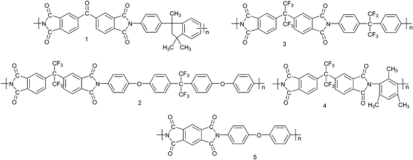 | ||
| Scheme 1 Molecular structures of aromatic PIs used for the preparation of low-k materials.16 | ||
4.4 Tissue engineering scaffolds
Tissue engineering scaffolds are polymeric composites designed for cell culture. They need to be porous and release precise amounts of guest species, e.g., growth factors and biotechnology drugs, at rates matching the physiological need of the tissue. Therefore, the challenges in constructing the tissue engineering scaffolds are (1) how to incorporate such biologically active guest species into a polymer host without loss or change of the activity; (2) how to control the morphology of the composite, e.g., to generate a proper pore size and size distribution that promote cell infiltration, and to control the porosity to adjust the release property. The combination of gas-like diffusivity and liquid-like solvability makes scCO2 capable of overcoming the above difficulties, facilitating the fabrication of tissue engineering scaffolds.Hile et al. prepared microporous poly(D,L-lactide-co-glycolide) foams containing encapsulated proteins.51 An aqueous protein emulsion in a polymer–solvent solution was firstly saturated with scCO2. Sudden depressurization under ambient conditions caused bubble nucleation and precipitation of the polymer. Proteins contained in the water phase of the emulsion were encapsulated within the foams, including basic fibroblast growth factor (bFGF). Therefore, pores and proteins were introduced into the polymer simultaneously. Moreover, active bFGF could be released at a relatively constant rate without an initial burst.
Howdle et al. used scCO2 to foam biodegradable polymers in the presence of thermal and solvent labile enzymes and impregnated them into porous polymer monoliths.52 Importantly, the structures and functions of the employed bioactive enzymes were well preserved after the foam and release process, indicating that the foamed polymer monoliths could be used as tissue engineering scaffolds. Tang et al. used a similar method to prepare a porous copolymer of carbohydrate lactone, acetic acid 5-acetoxy-6-oxotetrahydropyran-2-yl methyl ester, and ε-caprolactone (PCL), incorporated with bovine serum albumin (BSA).53 Their protein-release experiment demonstrated that the release of BSA from porous copolymer films had a stable release rate without an initial burst. It was found that on these foams MC3T3 had a relative high metabolic activities and spreading rate, while primary bovine chondrocytes showed a uniform distribution throughout the foam and penetrated into the random copolymer foam.
4.5 Filtration
Membrane fouling is one of the most important challenges in filtration application. In order to develop a “greener” route to prepare antifouling ultrafiltration membranes, polymers can be foamed by the scCO2-induced phase inversion method, leading to highly pure materials with adjustable pore size and morphology. Poly(acrylonitrile) (PAN)-based membranes have sufficient chemical stability and good membrane performance in aqueous filtration applications, but still suffer from significant fouling. Barroso et al. prepared a graft copolymer of poly(acrylonitrile)-graft-poly(ethylene oxide) (PAN-g-PEO) in scCO2, which was blended with PAN to fabricate porous membranes using the scCO2-induced phase inversion method.54 These ultrafiltration membranes had the largest permeability of 5840 L (m2 h MPa)−1 for pure water. When filtrating a water solution of BSA and starch, 71–90% of initial flux could be recovered after washing the membranes without aggressive cleaning procedures, showing effective resistance to irreversible fouling. Compared with conventional technologies, the scCO2-assisted process endows the blended membranes with larger permeability and good resistance to irreversible fouling, indicating that the technology is an efficient process to prepare fouling resistant membranes for biomacromolecule separations.5 Conclusions and perspectives
The advantages afforded by polymer foams continue generating ongoing interest in the development of material synthesis and processing. Nanoporous polymers are of considerable importance since they can be used directly or as templates for advanced microelectronic processing. As an emerging strategy for the preparation of nanoporous polymeric materials, scCO2 and CXL techniques demonstrate their advantages of environmental friendliness, processing simplicity, pore formation without sacrificing any components of the material, and capability of producing adjustable pore size, porosity and morphology. They have successfully produced a variety of porous morphologies, including closed nanocells, networks and nanosheets, in both polymeric thin films and monoliths, making the method attractive to researchers outside the nanocommunity. In addition to offering materials with varieties of promising applications, they also shed light on the foaming mechanism.In our opinion, the future challenges will include the following points:
(1) The unambiguous elucidation of the foaming mechanism. There is a lack of in-depth understanding of the formation of nanofoams in a sealed vessel at high pressure. For example, the subtle interplay between the porogen and the constituent blocks, the reconstruction of molecular chains, phase transition, etc. still remain largely unclear. Theoretical endeavours need to be put into this area to address these open questions, and to guide how to optimize the foaming process experimentally to achieve materials with desired structures and functions.
(2) More accurate, general and convenient characterization techniques. Since the size, shape, connectivity, and dispersion of pores and the porosity of materials significantly impact their performances, the quantification of these properties is also of importance.
(3) Generalization of the nanostructure fabrication techniques. The strategies of selective removal of minority domains in BCP templates have been limited by their harsh removal conditions and residual decomposed fragments. However, the non-destructive technique of selectively swelling BCP by scCO2 is restricted by the limited CO2-philic monomers. Therefore, new CO2-philic monomers and polymers are expected. On the other hand, CXLs can be used to selectively swell BCPs without CO2-philic moieties because of their improved polarity and dissolving capacity. Moreover, this strategy still should be developed and applied to foam more kinds of BCPs and to produce more nanoporous morphologies.
(4) New applications of nanoporous thin films. More efforts should be devoted to further exploring the potential of these films, including nonisotropic conductors, optically, magnetically and electrically active materials, and wave-absorbing materials. We believe that a whole wealth of new applications for nanoporous thin films will emerge, together with better understanding of their formation and control of their structures and properties.
Therefore, it is envisaged that supercritical nanofoaming techniques will undergo rapid development and there will be both theoretical and practical breakthroughs in the near future, through the combined efforts from chemists, physicists, and material scientists.
Acknowledgements
L.L. gratefully acknowledges the National Natural Science Foundation of China (No. 51373143, 51035002 and 21174116), Fundamental Research Funds for the Central Universities (2013SH003), and the Key Laboratory for Ultrafine Materials of Ministry of Education.Notes and references
- D. Wu, F. Xu, B. Sun, R. Fu, H. He and K. Matyjaszewski, Chem. Rev., 2012, 112, 3959–4015 CrossRef CAS PubMed
.
-
M. A. Hillmyer, in Block Copolymers II, ed. V. Abetz, 2005, vol. 190, pp. 137–181 Search PubMed
.
- T. Thurn-Albrecht, J. Schotter, C. A. Kastle, N. Emley, T. Shibauchi, L. Krusin-Elbaum, K. Guarini, C. T. Black, M. T. Tuominen and T. P. Russell, Science, 2000, 290, 2126–2129 CrossRef CAS PubMed
.
- D. L. Tomasko, H. Li, D. Liu, X. Han, M. J. Wingert, L. J. Lee and K. W. Koelling, Ind. Eng. Chem. Res., 2003, 42, 6431–6456 CrossRef CAS
.
- A. I. Cooper, Adv. Mater., 2003, 15, 1049–1059 CrossRef CAS
.
- P. G. Jessop and B. Subramaniam, Chem. Rev., 2007, 107, 2666–2694 CrossRef CAS PubMed
.
- J. L. Kendall, D. A. Canelas, J. L. Young and J. M. DeSimone, Chem. Rev., 1999, 99, 543–564 CrossRef CAS PubMed
.
- L. J. M. Jacobs, M. F. Kemmere and J. T. F. Keurentjes, Green Chem., 2008, 10, 731–738 RSC
.
- S. Siripurapu, J. A. Coughlan, R. J. Spontak and S. A. Khan, Macromolecules, 2004, 37, 9872–9879 CrossRef CAS
.
- D. J. Frankowski, S. Fournier-Bidoz, I. Manners, G. A. Ozin, S. A. Khan and R. J. Spontak, Macromol. Chem. Phys., 2004, 205, 2398–2408 CrossRef CAS
.
- W. Zhai, J. Yu, L. Wu, W. Ma and J. He, Polymer, 2006, 47, 7580–7589 CrossRef CAS
.
- C. Zeng, X. Han, L. J. Lee, K. W. Koelling and D. L. Tomasko, Adv. Mater., 2003, 15, 1743–1747 CrossRef CAS
.
- S. Siripurapu, J. M. DeSimone, S. A. Khan and R. J. Spontak, Macromolecules, 2005, 38, 2271–2280 CrossRef CAS
.
- B. Krause, K. Diekmann, N. F. A. van der Vegt and M. Wessling, Macromolecules, 2002, 35, 1738–1745 CrossRef CAS
.
- B. Krause, H. J. P. Sijbesma, P. Münüklü, N. F. A. van der Vegt and M. Wessling, Macromolecules, 2001, 34, 8792–8801 CrossRef CAS
.
- B. Krause, G. H. Koops, N. F. A. van der Vegt, M. Wessling, M. Wübbenhorst and J. van Turnhout, Adv. Mater., 2002, 14, 1041–1046 CrossRef CAS
.
- F. S. Bates and G. H. Fredrickson, Phys. Today, 2008, 52, 32–38 CrossRef
.
- R. A. Pai, R. Humayun, M. T. Schulberg, A. Sengupta, J. N. Sun and J. J. Watkins, Science, 2004, 303, 507–510 CrossRef CAS PubMed
.
- L. Li, T. Nemoto, K. Sugiyama and H. Yokoyama, Macromolecules, 2006, 39, 4746–4755 CrossRef CAS
.
- L. Li, H. Yokoyama, T. Nemoto and K. Sugiyama, Adv. Mater., 2004, 16, 1226–1229 CrossRef CAS
.
- H. Yokoyama, L. Li, C. Dutriez, Y. Iwakura, K. Sugiyama, H. Masunaga, S. Sasaki and H. Okuda, Macromolecules, 2008, 41, 8626–8631 CrossRef CAS
.
- H. Yokoyama, L. Li, T. Nemoto and K. Sugiyama, Adv. Mater., 2004, 16, 1542–1546 CrossRef CAS
.
- H. Yokoyama, E. J. Kramer, M. H. Rafailovich, J. Sokolov and S. A. Schwarz, Macromolecules, 1998, 31, 8826–8830 CrossRef CAS
.
- R. Zhang, C. Dutriez, K. Sugiyama, T. Ishizone and H. Yokoyama, Soft Matter, 2011, 7, 4032–4038 RSC
.
- L. Li and H. Yokoyama, Angew. Chem., Int. Ed., 2006, 45, 6338–6341 CrossRef CAS PubMed
.
- T. Sarbu, T. Styranec and E. J. Beckman, Nature, 2000, 405, 165–168 CrossRef CAS PubMed
.
- R. Zhang and H. Yokoyama, Macromolecules, 2009, 42, 3559–3564 CrossRef CAS
.
- J. L. Gong, A. J. Zhang, H. Bai, Q. K. Zhang, C. Du, L. Li, Y. Z. Hong and J. Li, Nanoscale, 2013, 5, 1195–1204 RSC
.
- Y. Wang, C. C. He, W. H. Xing, F. B. Li, L. Tong, Z. Q. Chen, X. Z. Liao and M. Steinhart, Adv. Mater., 2010, 22, 2068–2072 CrossRef CAS PubMed
.
- P. Wang, J. Ma, F. Shi, Y. Ma, Z. Wang and X. Zhao, Ind. Eng. Chem. Res., 2013, 52, 10355–10363 CrossRef CAS
.
- T. Barroso, M. Temtem, T. Casimiro and A. Aguiar-Ricardo, J. Supercrit. Fluids, 2009, 51, 57–66 CrossRef CAS
.
- E. Reverchon and S. Cardea, Ind. Eng. Chem. Res., 2006, 45, 8939–8945 CrossRef CAS
.
- E. Reverchon, S. Cardea and E. Schiavo Rappo, J. Supercrit. Fluids, 2008, 45, 356–364 CrossRef CAS
.
- A. M. Donald, Nat. Mater., 2003, 2, 511–516 CrossRef CAS PubMed
.
- A. J. Koster and D. A. Agard, J. Struct. Biol., 1997, 120, 207–209 CrossRef PubMed
.
- S. van Bavel, E. Sourty, G. de With, S. Veenstra and J. Loos, J. Mater. Chem., 2009, 19, 5388–5393 RSC
.
- H. Sai, K. W. Tan, K. Hur, E. Asenath-Smith, R. Hovden, Y. Jiang, M. Riccio, D. A. Muller, V. Elser, L. A. Estroff, S. M. Gruner and U. Wiesner, Science, 2013, 341, 530–534 CrossRef CAS PubMed
.
- M. L. Mather, S. P. Morgan, L. J. White, H. Tai, W. Kockenberger, S. M. Howdle, K. M. Shakesheff and J. A. Crowe, Biomed. Mater., 2008, 3, 015011 CrossRef PubMed
.
- T. Shinkai, M. Ito, K. Sugiyama, K. Ito and H. Yokoyama, Soft Matter, 2012, 8, 5811–5817 RSC
.
- A. Naudon and D. Thiaudiere, J. Appl. Crystallogr., 1997, 30, 822–827 CrossRef CAS
.
- H. Yokoyama, C. Dutriez, L. Li, T. Nemoto, K. Sugiyama, S. Sasaki, H. Masunaga, M. Takata and H. Okuda, J. Chem. Phys., 2007, 127, 014904 CrossRef PubMed
.
- S. Brunauer, P. H. Emmett and E. Teller, J. Am. Chem. Soc., 1938, 60, 309–319 CrossRef CAS
.
- E. P. Barrett, L. G. Joyner and P. P. Halenda, J. Am.
Chem. Soc., 1951, 73, 373–380 CrossRef CAS
.
- L. J. D. Frink and F. van Swol, Langmuir, 1999, 15, 3296–3301 CrossRef CAS
.
- E. W. Washburn, Phys. Rev., 1921, 17, 273–283 CrossRef
.
- J. M. Ha, J. H. Wolf, M. A. Hillmyer and M. D. Ward, J. Am. Chem. Soc., 2004, 126, 3382–3383 CrossRef CAS PubMed
.
- R. Butler, I. Hopkinson and A. I. Cooper, J. Am. Chem. Soc., 2003, 125, 14473–14481 CrossRef CAS PubMed
.
- J. Zhang, B. Han, J. Li, Y. Zhao and G. Yang, Angew. Chem., Int. Ed., 2011, 50, 9911–9915 CrossRef CAS PubMed
.
- C. Dutriez, K. Satoh, M. Kamigaito and H. Yokoyama, Macromolecules, 2007, 40, 7433–7436 CrossRef CAS
.
- G. Maier, Prog. Polym. Sci., 2001, 26, 3–65 CrossRef CAS
.
- D. D. Hile, M. L. Amirpour, A. Akgerman and M. V. Pishko, J. Controlled Release, 2000, 66, 177–185 CrossRef CAS PubMed
.
- S. M. Howdle, M. S. Watson, M. J. Whitaker, V. K. Popov, M. C. Davies, F. S. Mandel, J. D. Wang and K. M. Shakesheff, Chem. Commun., 2001, 109–110 RSC
.
- M. Tang, M. Purcell, J. A. M. Steele, K.-Y. Lee, S. McCullen, K. M. Shakesheff, A. Bismarck, M. M. Stevens, S. M. Howdle and C. K. Williams, Macromolecules, 2013, 46, 8136–8143 CrossRef CAS
.
- T. Barroso, M. Temtem, T. Casimiro and A. Aguiar-Ricardo, J. Supercrit. Fluids, 2011, 56, 312–321 CrossRef CAS
.
| This journal is © The Royal Society of Chemistry 2014 |


