 Open Access Article
Creative Commons Attribution 3.0 Unported Licence
New bonding modes of carbon and heavier group 14 atoms Si–Pb
Gernot
Frenking
*a,
Ralf
Tonner
a,
Susanne
Klein
a,
Nozomi
Takagi
b,
Takayazu
Shimizu
a,
Andreas
Krapp
a,
Krishna K.
Pandey
c and
Pattiyil
Parameswaran
d
aFachbereich Chemie, Philipps-Universität Marburg, Hans-Meerwein-Strasse, D-35032 Marburg, Germany. E-mail: frenking@chemie.uni-marburg.de
bFukui Institute of Fundamental Chemistry, Kyoto University, Japan
cSchool of Chemical Sciences, Devi Ahilya University Indore, Indore-452017, India
dDepartment of Chemistry, National Institute of Technology Calicut, NIT Campus P.O., Calicut - 673 601, India
First published on 11th June 2014
Abstract
Recent theoretical studies are reviewed which show that the naked group 14 atoms E = C–Pb in the singlet 1D state behave as bidentate Lewis acids that strongly bind two σ donor ligands L in the donor–acceptor complexes L→E←L. Tetrylones EL2 are divalent E(0) compounds which possess two lone pairs at E. The unique electronic structure of tetrylones (carbones, silylones, germylones, stannylones, plumbylones) clearly distinguishes them from tetrylenes ER2 (carbenes, silylenes, germylenes, stannylenes, plumbylenes) which have electron-sharing bonds R–E–R and only one lone pair at atom E. The different electronic structures of tetrylones and tetrylenes are revealed by charge- and energy decomposition analyses and they become obvious experimentally by a distinctively different chemical reactivity. The unusual structures and chemical behaviour of tetrylones EL2 can be understood in terms of the donor–acceptor interactions L→E←L. Tetrylones are potential donor ligands in main group compounds and transition metal complexes which are experimentally not yet known. The review also introduces theoretical studies of transition metal complexes [TM]–E which carry naked tetrele atoms E = C–Sn as ligands. The bonding analyses suggest that the group-14 atoms bind in the 3P reference state to the transition metal in a combination of σ and π∥ electron-sharing bonds TM–E and π⊥ backdonation TM→E. The unique bonding situation of the tetrele complexes [TM]–E makes them suitable ligands in adducts with Lewis acids. Theoretical studies of [TM]–E→W(CO)5 predict that such species may becomes synthesized.
1. Introduction
This review summarizes recent theoretical work which deals with molecules where novel types of chemical bonds of group 14 atoms C–Pb in main group compounds and transition metal complexes were found. Experimental and theoretical evidence suggest that there are carbon compounds such as carbodiphosphorane C(PPh3)2 – known since 19611 – which are best described in terms of donor–acceptor interactions L→C←L between a bare carbon atom in the excited 1D state and two strong σ donors L, namely divalent carbon(0) compounds CL2. The term carbone has been suggested for these molecules which exhibit a chemical reactivity that is clearly different from carbenes CR2. The same bonding situation may also be found in the heavier tetrylone homologues EL2 (E = Si–Pb). Stable silylones SiL2 and germylones GeL2 could become synthesized after theoretical studies suggested that they might exist.We also review theoretical studies of transition metal complexes [TM]–C which have a bare carbon atom as ligand. Examples of such carbon complexes have been synthesized in 2002 where the ruthenium species [(PCy3)2Cl2Ru(C)] could become isolated.2 A formal electron count which takes the carbon atom as two-electron donor suggests that the molecule is a 16 valence-electron complex. The bonding analysis shows that the bare carbon atom which is isolobal to CO binds through its 3P ground state to the transition metal which yields two electron-sharing bonds and one donor–acceptor bond. This makes carbon a formal four-electron donor which indicates that [(PCy3)2Cl2Ru(C)] is actually a Ru(IV) compound. Theoretical studies of carbon complexes [TM]–C and heavier group 14 homologues [TM]–E (E = Si–Pb) which are experimentally not known are discussed here.
2. Divalent carbon(0) compounds (carbones)
The vast majority of organic compounds which until 1988 were known as stable species in condensed phase exhibit carbon atoms that use all four valence electrons in single, double or triple bonds with other elements across the periodic table (Scheme 1a). Except for a very few special cases such as the notorious CO,3 carbon appears nearly always as tetravalent C(IV)4 in stable organic compounds. The situation changed when Bertrand5 in 1988 and Arduengo6 in 1991 isolated compounds which are now recognized7 as stable carbenes CR2. In carbenes, carbon uses only two of its valence electrons while the remaining two retain as a lone electron pair (Scheme 1b). The chemistry of N-heterocyclic carbenes (NHCs) has become a particular focus of synthetic chemistry because NHCs are versatile ligands in transition metal complexes which were found very useful as powerful catalysts.8 The carbene chemistry of divalent carbon(II) compounds is now well established in organic synthesis.9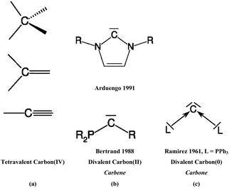 | ||
| Scheme 1 Schematic representation of (a) tetravalent carbon(IV) compounds; (b) divalent carbon(II) compounds (carbenes), (c) divalent carbon(0) compounds (carbones). | ||
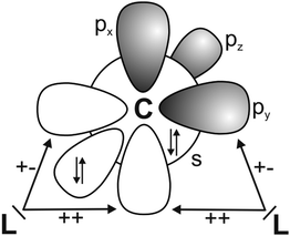
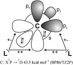
It has recently been recognized that there are organic compounds in which carbon exhibits yet another bonding situation. Divalent carbon(0) compounds CL2 possess a carbon atom which retains all four valence electrons as two lone pairs and where the bonding to the σ donor ligands L occurs through donor–acceptor interactions L→C←L (Scheme 1c). The electronic reference state of carbon in CL2 is the excited 1D singlet state with the electron configuration 1s22s22px02py02pz2 which is 29.1 kcal mol−1 higher in energy than the 3P ground state (Fig. 1).10 The donation from the lone-pair electrons of the ligands takes place from the in-phase (+,+) combination of the donor orbitals into the vacant 2px orbital (σ symmetry) and from the out-of-phase (+,−) combination of the donor orbitals into the vacant 2py orbital (in-plane π∥ symmetry). The orientation of the carbon 2pz2 orbital is orthogonal to the CL2 plane, i.e. it becomes the out-of-plane p(π⊥) lone pair orbital. The excitation energy 3P → 1D is compensated by the strong donor–acceptor bonding between the Lewis base L and the (double) Lewis acid (1D) carbon. The name carbone has been suggested11 for the latter divalent carbon(0) compounds in analogy to the name carbene for divalent carbon(II) compounds CR2 which have only one lone pair and two electron-sharing bonds C–R. Another important difference between carbones and carbenes is that the former compounds are π donors while the latter are usually weak π acceptors.
The first carbone was already synthesized in 1961 when Ramirez reported about the isolation of the carbodiphosphorane C(PPh3)2.1 The chemistry of carbodiphosphoranes was systematically explored in experimental work in the following years.12 A critical examination of the bonding description in the past literature shows that the carbon–phosphorous bond in carbodiphosphoranes is usually classified as diylide which is sketched with mesomeric structures as shown in Fig. 2a. This picture was already suggested by Ramirez in his 1961 publication1 when the structure of hexaphenylcarbodiphosphorane was not known yet. It was not until 1978 when the first X-ray structural analysis revealed that C(PPh3)2 has a strongly bent P–C–P angle of 131.7°.13 Recent DFT calculations gave a geometry which is in very good agreement with the experimental data (Fig. 2b).14 Inspection of the frontier orbitals of C(PPh3)2 showed that the HOMO is a π-type lone pair orbital while the HOMO−1 is a σ-type lone pair orbital (Fig. 2c and d).15
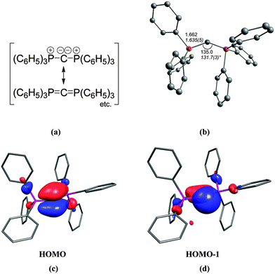 | ||
| Fig. 2 (a) Sketch of the bonding situation in hexaphenylcarbodiphosphorane as suggested by Ramirez.1 (b) Calculated (BP86/SVP) and experimental (in italics) geometry of C(PPh3)2. Frontier orbitals (c) HOMO and (d) HOMO−1 of C(PPh3)2.16 | ||
The description of the bonding situation in carbodiphosphoranes in terms of donor–acceptor interactions Ph3P→C←PPh3 was put forward in 2006 in a combined theoretical and experimental study by Tonner et al.16 providing crucial support for the postulated Lewis structure by Kaska et al. from 1973.17 The authors had analyzed in a preceding study the nature of the carbon–carbon bond between carbodiphosphorane and CO2 as well as CS2 yielding the adducts X2C–C(PPh3)2 (X = O, S) which were isolated and characterized through an X-ray structure analysis (Fig. 3).18 The complexes possess rather short carbon–carbon bonds which are shorter than a standard single bond. With the help of charge- and energy decomposition analyses, they identified a donor–acceptor bond X2C←C(PPh3)2 which has a dominant σ component and a weaker π component. It was concluded that carbodiphosphoranes C(PR3)2are double electron pair donors having σ- and π-carbon lone-pair orbitals.18 The latter finding was elaborated in the 2006 theoretical study where the twofold donor strength of carbodiphosphoranes C(PR3)2 with different substituents R with respect to H+ and the Lewis acids BH3, BCl3 and AlCl3 was estimated and analyzed using ab initio and DFT methods.16 The calculations showed that carbodiphosphoranes have not only a very large first proton affinity (PA) which classifies them as very strong bases. They also have a very large second PA which agrees with the notion of two lone pairs. A subsequent theoretical study of the first and second proton affinities of carbon bases showed that the first PA of carbodiphosphoranes C(PR3)2 has a similar strength as the first PA of NHCs but that C(PR3)2 exhibit a significantly higher second PA than NHCs.19 Pertinent examples are shown in Table 1. The calculations also predicted that the double Lewis base C(PPh3)2 is capable of binding two BH3 molecules at the carbon lone pairs in the stable complex (H3B)2–C(PPh3)2 while NHC binds only one BH3 at the carbon atom.16 The theoretical finding about the carbodiphosphorane adduct was verified by the isolation of the complex [{(μ-H)H4B2}C{PPh3}2](B2H7) where the (H3B)2 moiety of (H3B)2–C(PPh3)2 releases one H− to excess B2H6 yielding the hydrogen bridged B2H5+ complex of carbodiphosphorane (Fig. 4a).20 Calculations of the model complex [{(μ-H)H4B2}C{PH3}2]+ showed that the carbon–borane bonding can be understood in terms of σ- and π-donation from the double donor C{PH3}2 to the B2H5+ acceptor (Fig. 4b).
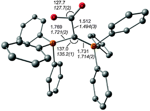 | ||
| Fig. 3 Calculated (BP86/SVP) and (in italics) experimental bond lengths and angles of O2C–C(PPh3)2.18,31 | ||
![[thin space (1/6-em)]](https://www.rsc.org/images/entities/char_2009.gif) 19
19
| R | NHCR![[thin space (1/6-em)]](https://www.rsc.org/images/entities/char_2009.gif) a a |
C(PR3)2 | ||
|---|---|---|---|---|
| 1st PA | 2nd PA | 1st PA | 2nd PA | |
| a Substituent at the nitrogen atom of NHC. b Second protonation at an olefinic carbon atom of the ring is ∼1 kcal mol−1 more favorable. | ||||
| H | 254.2 | 47.7b | 255.7 | 114.4 |
| Me | 262.3 | 71.8 | 278.4 | 156.2 |
| Ph | 264.7 | 100.1 | 280.0 | 185.6 |
| NH2 | 253.9 | 76.7 | 280.0 | 153.5 |
| NMe2 | 259.8 | 106.5 | 279.9 | 174.9 |
| t Bu | 270.6 | 92.3 | ||
| Mesityl | 270.4 | 105.3 | 280.7 | 201.1 |
| Adamantyl | 274.9 | 105.7 | ||
| Cyclohexyl | 280.5 | 184.0 | ||
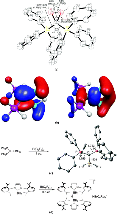 | ||
| Fig. 4 (a) Calculated at BP86/SVP and (in parentheses) experimental bond lengths and angles of [{(μ-H)H4B2}C{PH3}2]+.20 (b) Plot of the HOMO and HOMO−1 of [{(μ-H)H4B2}C{PH3}2]+. (c) Reaction of (H3B)←C(PPh3)2 with B(C6F5)3 yielding the complex [(H2B)⇐C(PPh3)2]+. (d) Reaction of (H3B)←NHC with B(C6F5)3 yielding the bridged complex [NHC→{(μ-H)H4B2}←NHC]+.21 | ||
The double donor ability of the carbodiphosphoranes C(PPh3)2 and the contrast to the carbene NHC was convincingly demonstrated in a joint experimental/theoretical work by Alcarazo, Thiel and co-workers.21 The authors realized that the σ and π lone pairs of a carbone could be utilized to bind a double Lewis acid such as BH2+ which has vacant σ and π orbitals (Fig. 4c). They reacted the complex (H3B)←C(PPh3)2 with the strong Lewis acid B(C6F5)3 and obtained in good yields the complex [(H2B)⇐C(PPh3)2]+ which has σ and π donor–acceptor bonds. The reaction of the carbene complex (H3B)←NHC with B(C6F5)3 gave the bridged adduct [NHC→{(μ-H)H4B2}←NHC]+ which is a striking example for the different chemical behaviour between a carbone and a carbene (Fig. 4d).
The calculations of carbodiphosphoranes C(PR3)2 were the starting point for further theoretical studies of divalent carbon(0) compounds CL2 with other ligands than phosphanes. Inspection of the literature revealed that the carbonyl homologues C(PPh3)(CO)22 and C(CO)223 which is usually described as carbon suboxide O![[double bond, length as m-dash]](https://www.rsc.org/images/entities/char_e001.gif) C
C![[double bond, length as m-dash]](https://www.rsc.org/images/entities/char_e001.gif) C
C![[double bond, length as m-dash]](https://www.rsc.org/images/entities/char_e001.gif) C
C![[double bond, length as m-dash]](https://www.rsc.org/images/entities/char_e001.gif) O are experimentally known for a long time. The bonding model in terms of donor–acceptor interactions L→C←L easily explains the finding that the divalent C(0) compounds with the better π acceptor ligands CO have larger bending angles τ for C(PPh3)(CO) (τ = 145.5°)22 and C(CO)2 (τ = 156.0°).24 There is a correlation between the π-acceptor strength of ligand L and the bending angle L–C–L in carbones CL2. Stronger π-acceptor ligands L induce more obtuse bending angles in CL2. The deviation from linearity and the very shallow bending potential of carbon suboxide is difficult to explain with the standard bonding model of a cumulene O
O are experimentally known for a long time. The bonding model in terms of donor–acceptor interactions L→C←L easily explains the finding that the divalent C(0) compounds with the better π acceptor ligands CO have larger bending angles τ for C(PPh3)(CO) (τ = 145.5°)22 and C(CO)2 (τ = 156.0°).24 There is a correlation between the π-acceptor strength of ligand L and the bending angle L–C–L in carbones CL2. Stronger π-acceptor ligands L induce more obtuse bending angles in CL2. The deviation from linearity and the very shallow bending potential of carbon suboxide is difficult to explain with the standard bonding model of a cumulene O![[double bond, length as m-dash]](https://www.rsc.org/images/entities/char_e001.gif) C
C![[double bond, length as m-dash]](https://www.rsc.org/images/entities/char_e001.gif) C
C![[double bond, length as m-dash]](https://www.rsc.org/images/entities/char_e001.gif) C
C![[double bond, length as m-dash]](https://www.rsc.org/images/entities/char_e001.gif) O while it becomes plausible when the donor–acceptor model L→C←L is employed.
O while it becomes plausible when the donor–acceptor model L→C←L is employed.
The litmus test for the predictive power of the donor–acceptor model L→C←L was provided by the theoretical study of the hitherto unknown class of carbodicarbenes C(NHC)2 which were suggested by Tonner and Frenking as stable molecules.25 Chemical experience has shown that NHCs have comparable donor properties as phosphanes which initiated a theoretical study of CL2 with NHC ligands L. The optimized geometry of C(NHCMe)2 (Fig. 5) shows a bending angle at the central carbon atom of 131.8°, which is similar to the value that is calculated for C(PPh3)2. The experimental verification of the theoretical work followed shortly after. Bertrand and co-workers isolated the benzoannelated carbodicarbene C(NHCBz)2 which is also shown in Fig. 5.26 The bending angle in C(NHCBz)2 is 134.8° which is close to the calculated value for C(NHCMe)2. Fürstner et al. reported at the same time about protonated carbon complexes which carry C(NHC)2 as ligands.27 The latter group recently synthesized a series of mixed carbones with one phosphane and various other ligands C(PPh3)(L) where L is CO, CNPh, PPh3 or a carbene CR2 with different substituent R.28 The authors investigated experimentally and theoretically the monoaurated and diaurated complexes (ClAu)2–C(PPh3)(L). It was suggested that the binding strength toward a second AuCl molecule should be used as measure of the carbone character of a compound CL2.
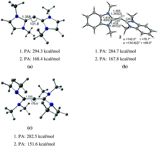 | ||
Fig. 5 Calculated (BP86/TZ2P) geometries and first and second proton affinities PA (MP2/TZVPP) of (a) carbodicarbene C(NHCMe)2. (b) Benzoannelated carbodicarbene C(NHCBz)2 (BP86/SVP). (c) Tetraaminoallene (NMe2)2C![[double bond, length as m-dash]](https://www.rsc.org/images/entities/char_e001.gif) C C![[double bond, length as m-dash]](https://www.rsc.org/images/entities/char_e001.gif) C(NMe2)2. Bond lengths are given in Å, angles in degree. Experimental data for C(NHCBz)2 are given in italics.26,32 C(NMe2)2. Bond lengths are given in Å, angles in degree. Experimental data for C(NHCBz)2 are given in italics.26,32 | ||
Fig. 5 shows also the optimized geometry of C[C(NMe2)2]2 which has a nearly linear C–C–C structure and a geometry where the C(NMe2)2 moieties are orthogonal to each other. The molecule may thus become identified as tetraaminoallene (TAA) (NMe2)2C![[double bond, length as m-dash]](https://www.rsc.org/images/entities/char_e001.gif) C
C![[double bond, length as m-dash]](https://www.rsc.org/images/entities/char_e001.gif) C(NMe2)2. However, the calculations predict that not only the first but also the second PA of the TAA which are very large have values similar to carbodicarbenes. The analogous TAA with ethyl groups instead of methyl has even a second PA of 175.8 kcal mol−1.19 Protonation at the central carbon atom is in both cases favoured over protonation at nitrogen. It has therefore been suggested that TAAs have “hidden carbone character” and that the bonding situation may also be described in terms of donor–acceptor interactions (NMe2)2C→C←C(NMe2)2.14 The chemical reactivity of TAAs supports the suggestion. The X-ray structure of doubly protonated TAAs where both protons bind to the central carbon atom has been reported.29 Even more convincing evidence for the “hidden carbone character” comes from the work of Viehe et al. who found that methyl and ethyl substituted TAAs react “extremely readily and in good yields with carbon dioxide” to give adducts which are analogous to the CO2 adduct of C(PPh3)2 which is shown in Fig. 3.30
C(NMe2)2. However, the calculations predict that not only the first but also the second PA of the TAA which are very large have values similar to carbodicarbenes. The analogous TAA with ethyl groups instead of methyl has even a second PA of 175.8 kcal mol−1.19 Protonation at the central carbon atom is in both cases favoured over protonation at nitrogen. It has therefore been suggested that TAAs have “hidden carbone character” and that the bonding situation may also be described in terms of donor–acceptor interactions (NMe2)2C→C←C(NMe2)2.14 The chemical reactivity of TAAs supports the suggestion. The X-ray structure of doubly protonated TAAs where both protons bind to the central carbon atom has been reported.29 Even more convincing evidence for the “hidden carbone character” comes from the work of Viehe et al. who found that methyl and ethyl substituted TAAs react “extremely readily and in good yields with carbon dioxide” to give adducts which are analogous to the CO2 adduct of C(PPh3)2 which is shown in Fig. 3.30
It becomes obvious that the nature of the ligand L has a very strong influence on the structure and reactivity of carbon compounds CL2. The methylene group L = CH2 has a triplet ground state which binds a carbon atom in its (3P) triplet ground state yielding the parent allene H2C![[double bond, length as m-dash]](https://www.rsc.org/images/entities/char_e001.gif) C
C![[double bond, length as m-dash]](https://www.rsc.org/images/entities/char_e001.gif) CH2. The first PA (182.4 kcal mol−1) and particularly the second PA (−5.2 kcal mol−1) are strikingly different to the first and second PA of TAAs.25a Diaminocarbenes C(NR2)2 have a singlet ground state and a very large singlet–triplet gap which supports donor–acceptor binding with a carbon atom in the (1D) excited state. The correlation between singlet–triplet gap and donor–acceptor bond will be further discussed in the section about the heavy group 14 homologues EL2 which is given below. TAAs have a very shallow bending mode like C(CO)2 and other compounds CL2 where L is a σ donor. Table 2 gives the calculated energies that are necessary to stretch the bending angle of various compounds CL2 from the equilibrium structure to the linear form or to the value of 136.9° which is the energy minimum value for C(PPh3)2. The calculated data indicate that very little energy is required for bending the molecules over a wide range.
CH2. The first PA (182.4 kcal mol−1) and particularly the second PA (−5.2 kcal mol−1) are strikingly different to the first and second PA of TAAs.25a Diaminocarbenes C(NR2)2 have a singlet ground state and a very large singlet–triplet gap which supports donor–acceptor binding with a carbon atom in the (1D) excited state. The correlation between singlet–triplet gap and donor–acceptor bond will be further discussed in the section about the heavy group 14 homologues EL2 which is given below. TAAs have a very shallow bending mode like C(CO)2 and other compounds CL2 where L is a σ donor. Table 2 gives the calculated energies that are necessary to stretch the bending angle of various compounds CL2 from the equilibrium structure to the linear form or to the value of 136.9° which is the energy minimum value for C(PPh3)2. The calculated data indicate that very little energy is required for bending the molecules over a wide range.
![[thin space (1/6-em)]](https://www.rsc.org/images/entities/char_2009.gif) 14
14
The structures and bonding situation in divalent carbon(0) parent compounds CL2 where L = PH3, PMe3, PPh3, CO, C(NHC)2, C(NHCMe)2, C(NMe2)2 and the first and second proton affinities and bond strengths of complexes of CL2 with main group Lewis acids BH3, CO2 and transition metal species W(CO)5 and Ni(CO)n (n = 2, 3) have been investigated in a series of theoretical studies by our group.14,31,32 The results show that carbones possess characteristic properties as double Lewis base which distinguishes them from carbenes. This was recognized in a comment article by Bertrand entitled “Rethinking carbon” where the author expressed his belief that the new concept may lead to “new chemistry and applications for carbon, the basic element for all known life.”33 Very recently, another set of carbones has been investigated with quantum chemical methods which show that there are not only new examples of the class of compounds that may become synthesized, but that molecules which have been isolated in the past were not recognized as carbones. Fig. 6 shows the calculated geometries of compounds 1–10 which have been studied.
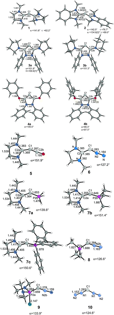 | ||
| Fig. 6 Calculated (BP86/SVP) geometries of some carbones CL1L2.32 Bond lengths are given in Å, angles in degree. Experimental data are given in italics.26,34 The figure has been adapted from ref. 32. | ||
Compound 1 is the saturated homologue of the unsaturated carbodicarbene C(NHCMe)2 which is discussed above while 2 is the benzoannelated carbodicarbene that was synthesized by Bertrand et al.26 Compounds 3 and 4 may be considered as “bent allenes” or alternatively as cyclic carbones where the dicoordinated C(0) atom binds to two diaminocarbene ligands (3a and 3b) or to two aminooxocarbene ligands (4a and 4b). The molecules have recently become synthesized.34 Because amino groups are better donors than oxo groups it can be expected that the carbone character of 3a and 3b is stronger than that of 4a and 4b. Compounds 5–10 exhibit various combinations of CL1L2 where L1, L2 are CO, N2, NHC or phosphane. Substituted homologues of compound 9 have been synthesized more than 20 years ago but they were introduced as phosphacumulenes.35
Fig. 7 shows the frontier orbitals HOMO and HOMO−1 of 1–10. It becomes obvious that the two highest lying MOs of all molecules appear like σ- and π-type lone-pair orbitals which suggest that the compounds may have chemical properties of carbones. Table 3 gives the calculated first and second PAs and the bond dissociation energy of complexes of 1–10 with one and with two BH3 ligands. The second PA of all compounds is rather high except for complexes CL1L2 where L1 is N2 or CO. However, all molecules 1–10 bind two Lewis acids BH3 in adducts, which – except for 4a and 4b – may be stable enough to become isolated in condensed phase. We are convinced that carbone chemistry is a very fruitful area of chemical research that waits to be explored.
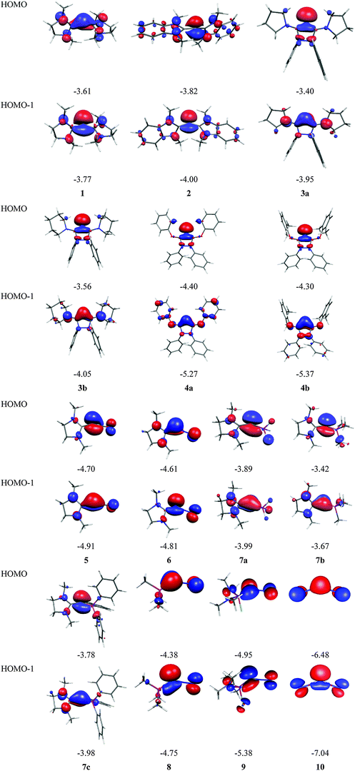 | ||
| Fig. 7 Shape and energy values [eV] of the frontier orbitals (BP86/TZVPP) of the carbones 1–10 which are shown in Fig. 6. | ||
![[thin space (1/6-em)]](https://www.rsc.org/images/entities/char_2009.gif) 32
32
| C(L1L2)a | L1 | L2 | (L1L2)C–(H+)n | (L1L2)C–(BH3)n | ||
|---|---|---|---|---|---|---|
| 1. PA | 2. PA | D e (n = 1) | D e (n = 2) | |||
| a The geometries of 1–10 are shown in Fig. 6. | ||||||
| 1 | NHCMe | NHCMe | 282.2 | 157.5 | 42.1 | 29.0 |
| 2 | NHCBz | NHCBz | 284.7 | 167.8 | 49.3 | 27.0 |
| 3a | Cyclo-bisdiaminocarbene | 296.5 | 158.7 | 58.4 | 20.0 | |
| 3b | Cyclo-bisdiaminocarbene | 293.5 | 158.0 | 57.6 | 16.9 | |
| 4a | Cyclo-aminooxocarbene | 285.2 | 131.0 | 53.9 | 5.7 | |
| 4b | Cyclo-aminooxocarbene | 284.3 | 133.3 | 53.0 | 9.5 | |
| 5 | NHCMe | CO | 243.3 | 99.0 | 30.7 | 17.4 |
| 6 | NHCMe | N2 | 244.1 | 111.5 | 31.9 | 20.7 |
| 7a | NHCMe | PH3 | 273.3 | 140.2 | 46.9 | 33.8 |
| 7b | NHCMe | PMe3 | 284.2 | 160.4 | 51.7 | 26.4 |
| 7c | NHCMe | PPh3 | 287.1 | 176.4 | 48.0 | 23.6 |
| 8 | PMe3 | N2 | 243.5 | 108.4 | 35.9 | 30.2 |
| 9 | PCl(NMe2)2 | N2 | 239.7 | 115.5 | 34.8 | 22.6 |
| 10 | N2 | N2 | 195.6 | 47.0 | 22.2 | 14.7 |
The nature of the donor–acceptor interaction in carbones L→C←L can be analyzed in great detail with the EDA (Energy Decomposition Analysis) method that was developed independently by Morokuma36 and by Ziegler and Rauk.37 The EDA analyzes the instantaneous interactions in a chemical bond A–B via a breakdown of the total interaction energy ΔEint between the frozen fragments A and B in the electronic reference state in three major terms: (a) the electrostatic interactions ΔEelstat between the frozen electronic charges and nuclei of the fragments; (b) the Pauli repulsion (exchange repulsion) ΔEPauli between electrons having the same spin; (c) the attractive orbital interactions ΔEorb which arise from the mixing of the occupied and vacant orbitals between and within the fragments.
| ΔEint = ΔEelstat + ΔEPauli + ΔEorb | (1) |
| ΔE(−De) = ΔEint + ΔEprep | (2) |
The orbital term ΔEorb can be further partitioned into contributions from orbitals which belong to different irreducible representations of the point group. The combination of the EDA with the NOCV (Natural Orbitals for Chemical Valence)38 charge partitioning method makes it possible to separate ΔEorb into pairwise contributions of the orbitals of the interacting fragments.39 The energy difference between the frozen fragments A and B in the electronic reference state and their equilibrium structures in the ground state gives the preparation energy ΔEprep. The sign converted sum of ΔEint + ΔEprep gives the bond dissociation energy De. Further details and pertinent examples for EDA and EDA-NOCV calculations are available from the literature.14,40
The EDA and EDA-NOCV methods can also be used to analyze the interactions between two fragments such as the carbon atom in the 1D electronic reference state and two ligands L in carbones CL2. The EDA-NOCV results for the carbodiphosphorane C(PPh3)2 and the carbodicarbene C(NHCMe)2 are shown in Table 4. The upper part of the table shows schematically the orbital interactions between the ligands and the carbon atom which are expected to be the most important contributions to ΔEorb. The in-phase (+,+) combination of the σ donor orbitals donate into the vacant px(σ) AO of C while the (+,−) out-of-phase combination donates electronic charge into the py(π∥) orbital of carbon. Some π backdonation L←C→L from the occupied pz(π⊥) AO of carbon into vacant ligand orbitals may also be found. The EDA-NOCV data in Table 4 provide a quantitative estimate of the different types of orbitals interactions as well as the other energy terms which are relevant for the carbon–ligand bonding.
| Compound | C(PPh3)2 | C(NHCMe)2 |
|---|---|---|
| a The value in parentheses gives the percentage contribution to the total attractive interactions (ΔEelstat + ΔEorb). b The value in parentheses gives the percentage contribution to the total orbital interactions. | ||
| Interacting fragments | C (1D) (PPh3)2 | C (1D) (NHCMe)2 |
| ΔEint | −192.3 | −267.3 |
| ΔEPauli | 738.4 | 917.6 |
| ΔEelstata | −284.0 (30.5%) | −354.6 (29.9%) |
| ΔEorba | −646.7 (69.5%) | −830.4 (70.1%) |
| ΔEσ (L→C←L (+,+) donation)b | −384.2 (59.4%) | −517.7 (62.3%) |
| ΔEπ∥ (L→C←L (+,−) donation)b | −190.5 (29.5%) | −196.0 (23.6%) |
| ΔEπ⊥ (L←C→L π backdonation)b | −65.0 (10.1%) | −98.8 (11.9%) |
| ΔErestb | −6.9 (1.1%) | −17.8 (2.1%) |
| ΔEprep | 63.6 | 87.3 |
| D e | 128.6 | 180.0 |
The calculations suggest that C–NHCMe bonds in the carbodicarbene C(NHCMe)2 are significantly stronger than the C–PPh3 bonds in C(PPh3)2. This holds for both, the intrinsic interaction energies ΔEint as well as for the bond dissociation energies De (Table 4). Inspection of the different energy terms indicate that the nature of the carbon–ligand bonding in the two complexes is very similar. Both L→C←L donor–acceptor bonds have ∼70% covalent character. The breakdown of the orbital term into the pairwise interactions shows that the major contribution comes from the in-phase (+,+) σ donation which provides ∼60% to ΔEorb while the out-of-phase (+,−) donation provides ∼30% (L = NHCMe) and ∼24% (L = PPh3) to the attractive orbital interactions. The π⊥ backdonation L←C→L is only a minor component in both complexes while the remaining orbital interactions are negligible. The EDA-NOCV results in Table 4 are a striking example for the strength of modern methods of bonding analysis to provide quantitative insight into the nature of chemical bonding which is based on accurate quantum chemical methods.
3. Divalent E(0) compounds (E = Si–Pb)
Is divalent E(0) chemistry of the group 14 elements restricted to E = C or is it also found for the heavier elements E = Si–Pb? Are there compounds EL2 for the latter tetrele41 atoms which can be described as donor–acceptor complexes L→E←L? Recent theoretical studies strongly suggest that divalent E(0) compounds EL2 are stable species which have already become synthesized. Like carbodiphosphoranes which were not recognized as divalent C(0) compounds, a similar situation exists for the heavier group 14 homologues.42
Scheme 2a shows three recently synthesized compounds which were introduced by Kira et al. as the first examples of heavier group 14 homologues of allenes that are stable in a condensed phase.43 The authors named the molecules trisilaallene, trigermaallene and 1,3-digermasilallene although the equilibrium geometries of the compounds are strongly bent with bond angles (cyc)E–E–E(cyc) between 122.6° (E = Ge) and 136.5° (E = Si). The bending angles are similar to the P–C–P angle in C(PPh3)2 of 131.7° and to the C–C–C angle of 131.8° which was calculated for C(NHCMe)2 and the experimental value of 134.8° for C(NHCBz)2. Scheme 2a sketches the bonding situation of trisilaallene, trigermaallene and 1,3-digermasilallene as they were suggested by Kira et al.43 The similar bending angle implies that the bonding of the (cyc)E–E–E(cyc) moiety might be described analogous to carbodicarbenes (Scheme 2b). However, there is an important difference between the carbodicarbenes C(NHC)2 and the “bent allenes” shown in Scheme 2. The carbene donor ligands in C(NHC)2 have nitrogen π donor atoms at the α position of the carbon donor atom while there is no π donor atom in the cyclic moieties of the heavier homologues. The trisilaallene, trigermaallene and 1,3-digermasilallene are thus substituted homologues of the parent systems E(EH2)2. Quantum chemical calculations by the groups of Apeloig44 and Veszprémi45 have shown that the classical (D2d) allene structure H2E![[double bond, length as m-dash]](https://www.rsc.org/images/entities/char_e001.gif) E
E![[double bond, length as m-dash]](https://www.rsc.org/images/entities/char_e001.gif) EH2 where E = Si, Ge is not a minimum on the potential energy surface (PES). Geometry optimization of the D2d form A of E(EH2)2 without symmetry constraints gives a strongly bent equilibrium structure B for H2E–E–EH2 with bending angles of ∼70° where the planes of the EH2 moieties are strongly rotated from the E3 plane (Fig. 8). The latter energy minima are ∼20 kcal mol−1 (E = Si) and ∼25 kcal mol−1 (E = Ge)45c lower lying than the D2d form which is a second-order saddle point with a degenerate imaginary frequency. Another energy minimum of E(EH2)2 is the cyclic form C (Fig. 8) which is separated by only a small energy barrier from structure B which has a similar energy as C. Apeloig and co-workers pointed out that B and C are bond-stretch isomers on the Si3H4 PES.44 It becomes obvious that the equilibrium geometry B bears little resemblance to a classical allene. A similar situation is found for acetylene and its heavier group 14 homologues E2H2 (E = Si–Pb) where the linear form HE
EH2 where E = Si, Ge is not a minimum on the potential energy surface (PES). Geometry optimization of the D2d form A of E(EH2)2 without symmetry constraints gives a strongly bent equilibrium structure B for H2E–E–EH2 with bending angles of ∼70° where the planes of the EH2 moieties are strongly rotated from the E3 plane (Fig. 8). The latter energy minima are ∼20 kcal mol−1 (E = Si) and ∼25 kcal mol−1 (E = Ge)45c lower lying than the D2d form which is a second-order saddle point with a degenerate imaginary frequency. Another energy minimum of E(EH2)2 is the cyclic form C (Fig. 8) which is separated by only a small energy barrier from structure B which has a similar energy as C. Apeloig and co-workers pointed out that B and C are bond-stretch isomers on the Si3H4 PES.44 It becomes obvious that the equilibrium geometry B bears little resemblance to a classical allene. A similar situation is found for acetylene and its heavier group 14 homologues E2H2 (E = Si–Pb) where the linear form HE![[triple bond, length as m-dash]](https://www.rsc.org/images/entities/char_e002.gif) EH is a second-order saddle point.46,47 The rather unusual energy minimum structures of the latter species and the difference to the carbon systems have been explained with the doublet/quartet gap of the EH fragments which yield the E2H2 structures.47
EH is a second-order saddle point.46,47 The rather unusual energy minimum structures of the latter species and the difference to the carbon systems have been explained with the doublet/quartet gap of the EH fragments which yield the E2H2 structures.47
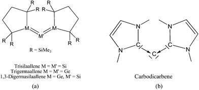 | ||
| Scheme 2 Schematic representation of the bonding situation in (a) heavy allenes as suggested by Kira43 and (b) carbodicarbenes C(NHC)2. | ||
 | ||
| Fig. 8 Schematic representation of the three structures A, B, C which were found as energy minima on the E(EH2)2 (E = Si, Ge) potential energy surfaces by Apeloig et al.44 | ||
Petrov and Veszprémi recognized the connection between the strongly bent equilibrium structure of the “trisilaallene” R2Si–Si–SiR2 and the carbones CL2 and they calculated various systems SiL2 where L = SiR2, NH3, PH3.45c The latter two compounds Si(EH3)2 which are related to carbodiphosphoranes have strongly bent geometries where the bending angle is 89.1° (E = N) and 88.2° (E = P). The NBO48 analysis predicts two lone-pairs at the silicon atom which let the authors suggest that the bonding situation should be written in analogy to the carbones as H3E→Si←EH3. The authors also calculated the structures of compounds R2Si–Si–SiR2 with acyclic and cyclic moieties SiR2 which are model substituents for the real substituent of the experimental “trisilaallene” of Kira et al.Table 5 shows the most important results. It becomes obvious that the bending angle of 136.5° which was measured for the isolated compound is due to steric repulsion between the bulky substituents. The agreement between the latter value and the bending angles of C(PPh3)2 (131.7°) and C(NHCBz)2 (134.8°) is fortuitous.
Another experimental finding which is relevant for the present work concerns the synthesis of the first “tristannaallene” [(t-but)3Si]2Sn![[double bond, length as m-dash]](https://www.rsc.org/images/entities/char_e001.gif) Sn
Sn![[double bond, length as m-dash]](https://www.rsc.org/images/entities/char_e001.gif) Sn[(t-but)3Si]2 which was already reported by Wiberg et al. in 1999 prior to the synthesis of the trisilaallene and trigermaallene.49 The X-ray structure analysis shows that the compound has a Sn–Sn–Sn bending angle of 156.0°. The authors noted that the 119Sn NMR signal of the central dicoordinated tin atom appears at a very low field which is more typical for a stannylene SnR2. On the basis of the experimental geometry and the NMR signal it was proposed that the bonding situation in the compounds is best described by the resonance formulae shown in Fig. 9.
Sn[(t-but)3Si]2 which was already reported by Wiberg et al. in 1999 prior to the synthesis of the trisilaallene and trigermaallene.49 The X-ray structure analysis shows that the compound has a Sn–Sn–Sn bending angle of 156.0°. The authors noted that the 119Sn NMR signal of the central dicoordinated tin atom appears at a very low field which is more typical for a stannylene SnR2. On the basis of the experimental geometry and the NMR signal it was proposed that the bonding situation in the compounds is best described by the resonance formulae shown in Fig. 9.
 | ||
| Fig. 9 Resonance structures which were suggested for Sn(SnR2)2 by Wiberg et al.49 | ||
The bonding situation in the carbodicarbene homologues 11E and in the “bent allenes” 12E with E = C–Pb has been investigated in recent theoretical studies by Takagi et al. who reported also about theoretical results of the related systems 13E–15E (Scheme 3).50 The results strongly suggest that the “allenes” which have been synthesized by Kira et al.43 should rather be classified as divalent E(0) compounds.
 | ||
| Scheme 3 Overview of the calculated two-coordinated compounds 11E–15E which were studied by Takagi et al.50 | ||
Fig. 10 shows the optimized geometries of 11E–15E (E = C–Sn). The carbon compounds 11C–15C possess much wider bending angles at the dicoordinated central atom than the heavier homologues. The difference is particularly striking between 12C, which shows the typical feature of an allene, i.e. a linear C![[double bond, length as m-dash]](https://www.rsc.org/images/entities/char_e001.gif) C
C![[double bond, length as m-dash]](https://www.rsc.org/images/entities/char_e001.gif) C moiety and an orthogonal alignment of the cyclopentyl ligands (dihedral angle of 90°/270°), and the heavier homologues 12E (E = Si–Sn) which have very acute bending angles E–E–E between 76.4° (E = Sn) and 79.4° (E = Ge). The cyclic ligands in the latter compounds are slightly twisted with respect to each other with dihedral angles between 31.0° (E = Ge, Sn) and 34.0° (E = Si). Inspection of the highest occupied orbitals of 11E–15E showed that all compounds possess high-lying MOs which can be identified as σ- and π-type lone-pair orbitals.50
C moiety and an orthogonal alignment of the cyclopentyl ligands (dihedral angle of 90°/270°), and the heavier homologues 12E (E = Si–Sn) which have very acute bending angles E–E–E between 76.4° (E = Sn) and 79.4° (E = Ge). The cyclic ligands in the latter compounds are slightly twisted with respect to each other with dihedral angles between 31.0° (E = Ge, Sn) and 34.0° (E = Si). Inspection of the highest occupied orbitals of 11E–15E showed that all compounds possess high-lying MOs which can be identified as σ- and π-type lone-pair orbitals.50
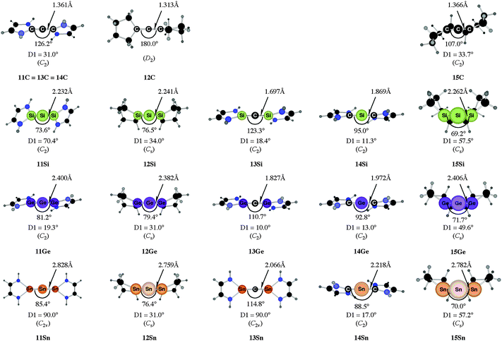 | ||
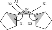
| Fig. 10 Calculated geometries of tetrylones 11E–15E (E = C, Si, Ge, Sn) showing the most important geometrical data.50b The figure has been adapted from ref. 50b. Distances are given in Å, angles in degree. The torsion angle D1 given below each structure is defined as the interplanar angle between the grey shaded area: | ||
The bending angles of the experimentally observed “trisilaallene” and “trigermaallene” which carry bulky trimethylsilyl groups at α and α′ position of the cyclic ligands are much wider than in 12E. Geometry optimizations of the compounds 12E′ (E = Si, Ge, Sn) which have trimethylsilyl groups at the α and α′ position show (Fig. 11) that the bending angles of 12E′ are much larger than those of 12E. The calculated values for 12Si′ (135.7°) and 12Ge′ (123.8°) are in very good agreement with the experimental values for the “trisilaallene” (136.5°) and “trigermaallene” (122.6°). The calculations suggest that the agreement between the experimental values for the “trisilaallene” and “trigermaallene” and the carbodicarbene and carbodiphosphoranes does not come from the similar bonding situation of the central E–E–E moiety in the carbon systems and the heavier homologues. The bonding angles in the parent systems of the heavier homologues are more acute than in the carbon species. The steric repulsion in 12E′ leads to bonding angles which are similar to those in C(NHC)2 and C(PR3)2. However, the much more acute bonding angles in the parent systems 12E (E = Si–Sn) which are <80° raise serious doubt whether these compounds should be considered as allenes. Moreover the calculations show that the molecules 11E–14E are rather flexible with respect to the bending angles at the central dicoordinated atom and the rotation of the cyclic ligands about the central E1–E2–E3 plane.
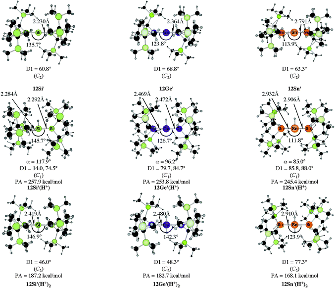 | ||
| Fig. 11 Calculated geometries of the tetrylones 12E′ and the singly protonated and doubly protonated species 12E′(H+) and 12E′(H+)2 (E = Si, Ge, Sn) which carry bulky Si(Me)3 substituents at the α and α′ position of the cyclic ligands of 12E.50b The figure has been adapted from ref. 50b. The angle α gives the bending angle of the E–H+ bond with respect to the E1–E2–E3 plane. Distances are given in Å, angles in degree. For the definition of the torsion angle D1 see Fig. 10. | ||
Fig. 11 shows also the calculated geometries of the singly and doubly protonated compounds 12E′(H+) and 12E′(H+)2 (E = Si–Sn) and the theoretically predicted first and second proton affinities. It becomes obvious that the “heteroallenes” 12E′ possess not only very large first PAs but also the second PAs are very big. The calculated values for the second PA (168.1–187.2 kcal mol−1) are similar to the second PA of C(PPh3)2 (185.6 kcal mol−1) and for C(NHCMe)2 (168.4 kcal mol−1). The geometries of the singly protonated compounds 12E′(H+) exhibit a particular feature. The E–H+ bond is not coplanar to the E1–E2–E3 plane which means that the central tetrele atom is protonated through the π-type orbital. The same situation is found in the protonated compounds of the parent systems 11E(H+)–15E(H+) (E = Si–Sn).50a,b This is strikingly different to the carbone compounds where carbon is always protonated at the σ lone pair yielding a C–H+ bond in 11C(H+), 12C(H+) and 15C(H+) which is coplanar to the central E–C–E plane.
Takagi et al. reported also about complexes of 11E–15E with one and with two Lewis acids BH3 as ligands.50b They also calculated transition metal complexes (CO)5W–D and (CO)3Ni–D with the ligands D = 11E–15E. Table 6 summarizes the theoretically predicted bond dissociation energies (BDEs) and proton affinities of the compounds. The calculated data suggest that the heavy-atom homologues 11E–15E (E = Si–Sn) possess not only large values for the first and second PAs. They also yield strongly bonded complexes with one but also with two BH3 Lewis acids. Surprisingly, the BDE of the second BH3 is in several complexes even higher than the BDE of the first BH3! The binding of the first BH3 ligand in 11E(BH3)–15E(BH3) prepares the central atom E quite well for the interaction with the second borane ligand. It should be noted that the BH3 ligands in some complexes are η3 coordinated to the E3 moiety while in other complexes they bind η1 to the central atom E. A detailed discussion of the geometries of the complexes is given in the paper by Takagi et al.50b Finally, we note that the compounds 11E–15E are strongly bonded ligands D in complexes (CO)5W–D and (CO)3Ni–D where their BDE is comparably strong as that of CO.
| a The second BH3 ligand does not bind to the divalent carbon atom. It dissociates during the geometry optimization. | |||||
|---|---|---|---|---|---|
| E = C | |||||
| 1st PA | 289.2 | 236.9 | Same as 1C | Same as 1C | 280.2 |
| 2nd PA | 148.4 | 87.6 | 73.8 | ||
| D 298o (BH3) | 60.2 | 6.9 | 55.3 | ||
| D 298o (BH3)2 | 19.4 | Diss.a | Diss.a | ||
| E = Si | |||||
| 1st PA | 249.7 | 237.9 | 261.8 | 275.9 | 228.8 |
| 2nd PA | 142.9 | 129.3 | 145.3 | 166.7 | 123.9 |
| D 298o (BH3) | 28.3 | 31.6 | 34.6 | 40.8 | 23.2 |
| D 298o (BH3)2 | 26.2 | 36.3 | 47.8 | 48.1 | 36.6 |
| D 298o [W(CO)5] | 41.2 | 42.0 | 38.5 | 53.0 | 37.9 |
| D 298o [Ni(CO)3] | 27.8 | 27.5 | 23.0 | 36.1 | 24.6 |
| E = Ge | |||||
| 1st PA | 255.0 | 229.9 | 263.9 | 275.7 | 220.3 |
| 2nd PA | 141.3 | 127.6 | 173.8 | 154.0 | 120.9 |
| D 298o (BH3) | 27.0 | 20.7 | 39.7 | 39.4 | 26.3 |
| D 298o (BH3)2 | 27.9 | 29.4 | 30.9 | 43.4 | 16.5 |
| D 298o [W(CO)5] | 45.0 | 35.9 | 41.1 | 54.0 | 31.0 |
| D 298o [Ni(CO)3] | 28.3 | 20.5 | 25.2 | 36.3 | 17.7 |
| E = Sn | |||||
| 1st PA | 260.9 | 226.0 | 276.8 | 277.9 | 225.7 |
| 2nd PA | 143.6 | 129.6 | 194.8 | 141.5 | 112.4 |
| D 298o (BH3) | 29.4 | 23.3 | 49.1 | 40.6 | 23.8 |
| D 298o (BH3)2 | 25.1 | 15.2 | 47.4 | 36.0 | 10.6 |
| D 298o [W(CO)5] | 53.5 | 30.6 | 53.9 | 59.5 | 28.6 |
| D 298o [Ni(CO)3] | 36.7 | 18.1 | 34.4 | 41.1 | 16.3 |
What is the reason for the drastically different equilibrium geometries and chemical properties of 11E–15E which show typical features of an allene when E = C while they exhibit divalent E(0) properties when E = Si–Pb? A straightforward answer to this question can be given when the relative energies of the interacting fragments L and E in the species EL2 in the lowest lying singlet and triplet states of the carbon compounds are compared with the heavier homologues. The explanation is based on the model which was introduced earlier by Trinquier and Malrieu51a,b and by Carter and Goddard51c,d who discussed the unusual structures of the heavy-atom homologues of ethylene E2H4 (E = Si–Pb) using the electronic singlet and triplet states of EH2. Fig. 12 shows qualitatively the orbital interactions in divalent E(0) compounds (top) and in allenes (bottom). The donor–acceptor bonds in the former species come from the interactions between singlet fragments ER2 and a group 14 atom E in the singlet (1D) state. The double bonds in allenes come from the electron-sharing interactions between triplet fragments ER2 and a group 14 atom E in the triplet (3P) state. Table 7 gives the calculated energy differences for atoms E, for NHC and cyclopentylidene (cycC) and their heavier homologues (E = Si–Pb).
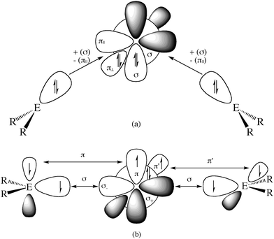 | ||
Fig. 12 Schematic representation of orbital interactions in (a) divalent E(0) compounds R2E→E←ER2 and (b) allenes R2E![[double bond, length as m-dash]](https://www.rsc.org/images/entities/char_e001.gif) E E![[double bond, length as m-dash]](https://www.rsc.org/images/entities/char_e001.gif) ER2. ER2. | ||
| Ea | ||||||
|---|---|---|---|---|---|---|
| 1D | 3P | Singlet | Triplet | Singlet | Triplet | |
| a Experimental excitation energies taken from: J. E. Sansonetti and W. C. Martin, Handbook of Basic Atomic Spectroscopic Data, National Institute of Standards and Technology, Gaithersburg, MD 20899, http://www.nist.gov/pml/data/handbook/index.cfm. b 6p21/2 ← 6p1/26p3/2 excitation. | ||||||
| E = C | 29.1 | 0.0 | 0.0 | 84.1 | 0.0 | 7.4 |
| E = Si | 18.0 | 0.0 | 0.0 | 60.8 | 0.0 | 27.1 |
| E = Ge | 20.4 | 0.0 | 0.0 | 50.5 | 0.0 | 31.0 |
| E = Sn | 24.6 | 0.0 | 0.0 | 37.2 | 0.0 | 31.2 |
| E = Pb | 22.4b | 0.0 | 0.0 | 30.5 | 0.0 | 33.8 |
Table 7 shows that the singlet fragments in C(NHC)2 are energetically favored over the triplet fragments by (2 × 84.1 kcal mol−1) − 29.1 kcal mol−1 = 139.1 kcal mol−1. This is in contrast to C(cycC)2 where the triplet fragments are favored over the singlet fragments by 29.1 kcal mol−1 − (2 × 7.4 kcal mol−1) = 14.3 kcal mol−1. The situation for the heavier group 14 homologues is different because the triplet → singlet excitation energy of atom E = Si–Pb is smaller than for carbon atom and the singlet → triplet excitation energy of cycE is clearly higher than that of cycC. For example, the singlet fragments in Si(NHSi)2 are favored over the triplet fragments by (2 × 60.8 kcal mol−1) − 18.0 kcal mol−1 = 103.6 kcal mol−1 and they are favored in Si(cycSi)2 by (2 × 27.1 kcal mol−1) − 18.0 kcal mol−1 = 36.2 kcal mol−1. A similar situation is found for the heavier homologues E = Ge–Pb. The bonding situation of a genuine allene in E(cycE)2 would only be possible if stronger binding interactions between the triplet fragments than the binding interactions between the singlet fragments compensate for the differences in the excitation energies. It has been shown, however, that E→E (E = Si–Pb) donor–acceptor interactions between singlet fragments may have the same strength as E–E electron-sharing interactions between open-shell fragments.47 The differences between the bonding situation in the heavier tetrele compounds and the carbon molecules can thus be attributed to the nature and energy levels of the electronic ground and excited states of the bonding fragments and to the strength of the interactions in the different electronic states.
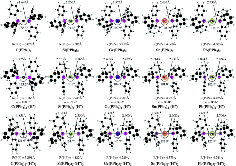
The experimental work about “trisilaallene” and “trigermaallene”43 and the theoretical studies of the parent systems 11E–15E50 gave rise to the question about the heavy group 14 homologues of carbodiphosphorane E(PPh3)2 (E = Si–Pb). The structures, bonding situation and double–donor properties were investigated in a theoretical study by Takagi, Tonner and Frenking.52 The experimentally yet unknown compounds were shown to be genuine examples of tetrylones EL2 which are predicted to have large first and second proton affinities as well as large bond dissociation energies of one and two Lewis acids BH3 and AuCl.
Fig. 13 shows the calculated equilibrium geometries of E(PPh3)2 and the singly and doubly protonated species E(PPh3)2–(H+) and E(PPh3)2–(H+)2. The calculations predict that the bending angle P–E–P in all systems becomes more acute for the heavier group-14 complexes where E = Si–Pb than for the parent carbone. The shape of the highest lying orbitals HOMO and HOMO − 1 of the neutral parent systems E(PPh3)2 exhibits the typical features of π lone-pair (HOMO) and σ lone-pair (HOMO − 1) (Fig. 14). Table 8 gives the calculated proton affinities of E(PPh3)2 in comparison with the PA values for the homologues E(NHC)2 (14E) and the divalent E(II) compounds NHE. It becomes obvious that the first PAs but particularly the second PAs of E(NHC)2 and E(PPh3)2 are much higher than those of the NHE compounds. This clearly identifies E(PPh3)2 and E(NHC)2 as divalent E(0) compounds while the NHE molecules are divalent E(II) compounds.
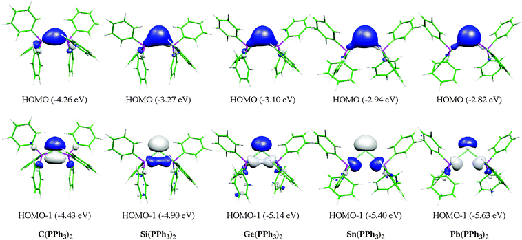 | ||
| Fig. 14 Graphical representation of HOMO (top) and HOMO − 1 (bottom) of compounds E(PPh3)2. Orbital energies (BP86/TZVPP) are given in eV. | ||
Further relevant information about the tetrele phosphoranes E(PPh3)2 are given in Table 9. The calculated bond dissociation energies for breaking the E-PPh3 bonds become significantly smaller for the heavier systems C ≫ Si > Ge > Sn > Pb but protonation at atom E strongly enhances the E-PPh3 bonds. This is a hint for possible synthesis of the neutral compounds which might becomes isolated via deprotonation of the cations E(PPh3)2–(H+) and E(PPh3)2–(H+)2. The calculated data also suggest that the tetrylones E(PPh3)2 are very strong donors toward one and two Lewis acids BH3 and AuCl. Unlike the proton affinities where the carbon system has larger first and second PAs than the heavier homologues, the bond strengths of E(PPh3)2 toward one and two BH3 and AuCl moieties are even bigger when E = Si–Pb compared with C(PPh3)2 except for the complexes Sn(PPh3)2–(BH3) and Pb(PPh3)2–(BH3). The calculated results are pointing toward a potentially fruitful and largely explored territory for experimental studies. Further theoretical information about the chemistry of tetrele phosphoranes E(PPh3)2 can be found in a recent theoretical study of transition metal complexes [(CO)5W–{E(PPh3)2}] and [(CO)5W–NHE] (E = C–Pb) where the ligand properties of tetrylenes and tetrylones are compared.53
|
D
e (Do)
E–(PPh3)2 |
D
e (Do)c
EH+–(PPh3)2 |
D
e (Do)c
E(H+)2–(PPh3)2 |
D
e (Do)
E(PPh3)2–BH3 |
D
e (Do)
E(PPh3)2(BH3)–BH3 |
D
e (Do)
E(PPh3)2–AuCl |
D
e (Do)
E(PPh3)2(AuCl)–AuCl |
|
|---|---|---|---|---|---|---|---|
| a E(PPh3)2→E(3P) + 2(PPh3). The values are given for one bond. b E(PPh3)2→E(1D) + 2(PPh3). The values are given for one bond. c The values are given for one bond. | |||||||
| C(PPh3)2 | 65.1a (63.0)a | 136.2 (131.8) | 264.9 (258.8) | 35.0 (31.1) | 20.8 (16.4) | 63.2 (61.8) | 52.5 (51.8) |
| Si(PPh3)2 | 26.7a (25.9)a | 68.2 (65.8) | 172.5 (169.2) | 37.5 (34.8) | 39.6 (37.2) | 80.4 (79.2) | 73.6 (72.5) |
| Ge(PPh3)2 | 22.9a (22.3)a | 62.2 (60.1) | 160.4 (157.7) | 35.1 (32.5) | 34.4 (31.9) | 77.0 (76.0) | 64.1 (63.0) |
| Sn(PPh3)2 | 16.7a (16.4)a | 50.0 (48.3) | 134.2 (132.2) | 31.9 (29.7) | 30.0 (27.7) | 74.8 (73.7) | 60.0 (59.1) |
| Pb(PPh3)2 | 13.7a (13.6)a | 44.9 (43.4) | 120.9 (119.4) | 31.6 (29.3) | 27.3 (25.2) | 73.8 (72.6) | 53.4 (52.6) |
There is a wealth of experimental and theoretical results which support the identification of a new class of tetrele compounds which are stable in a condensed phase where the group-14 atom has a divalent E(0) valence state. The bonding situation in the tetrylones EL2 should be described in terms of donor–acceptor interaction L→E←L where the tetrele atom E = C–Pb retains its valence electrons as two lone pairs. The suggested nomenclature for the tetrylones EL2 is shown in Table 10. Very recently, the first heavier homologues of carbodicarbenes C(NHC)2 could become synthesized and structurally characterized by X-ray analysis. Roesky and co-workers reported about the isolation of the silylone and germylones E(CAAC)2 (E = Si, Ge) where the ligand CAAC (Cyclic Alkyl Amino Carbene) has only one nitrogen atom in the N-heterocyclic carbene moiety (Fig. 15a).54 The silylone and germylone complexes E(NHC–NHC) where the NHC fragments are bonded to each other in a bidentate ligand have been synthesized by Driess et al. (Fig. 15b).55
 | ||
| Fig. 15 Schematic representation of the silylones and germylones E(CAAC)2 and E(NHC–NHC) (E = Si, Ge) which have been isolated.54,55 | ||
4. Transition metal–carbon complexes [TM]–C
Carbones CL2 are not the only novel class of compounds that has been introduced in chemistry in the recent past where a bare carbon atom is bonded via donor–acceptor interactions. Another class are transition metal (TM) compounds with a terminal carbon atom as ligand [TM]–C which can be regarded as the endpoint in the series TM–alkyl [TM]–CR3→TM–carbene [TM]![[double bond, length as m-dash]](https://www.rsc.org/images/entities/char_e001.gif) CR2→TM–carbyne [TM]
CR2→TM–carbyne [TM]![[triple bond, length as m-dash]](https://www.rsc.org/images/entities/char_e002.gif) CR complexes. Alkyl complexes of transition metals are already known since 1848 when Frankland accidentally synthesized diethylzinc while attempting to prepare free ethyl radicals.56 Molecules with a TM
CR complexes. Alkyl complexes of transition metals are already known since 1848 when Frankland accidentally synthesized diethylzinc while attempting to prepare free ethyl radicals.56 Molecules with a TM![[double bond, length as m-dash]](https://www.rsc.org/images/entities/char_e001.gif) CR2 double bond and TM
CR2 double bond and TM![[triple bond, length as m-dash]](https://www.rsc.org/images/entities/char_e002.gif) CR triple bond were isolated much later.57–61 The chemical reactivity of the compounds which possess metal–carbon double and triple bonds suggests that two classes of carbene and carbyne complexes can be distinguished which exhibit different reactivities. The metal–ligand bonding in Fischer-type carbene and carbyne complexes57,58 is best described in terms of donor–acceptor bonding using the Dewar–Chatt–Duncanson (DCD) model62 between closed-shell fragments while the bonding in Schrock carbenes and carbynes60,61 should be considered as electron-sharing interactions between triplet (for carbenes) and quartet (for carbynes) fragments (Fig. 16).63
CR triple bond were isolated much later.57–61 The chemical reactivity of the compounds which possess metal–carbon double and triple bonds suggests that two classes of carbene and carbyne complexes can be distinguished which exhibit different reactivities. The metal–ligand bonding in Fischer-type carbene and carbyne complexes57,58 is best described in terms of donor–acceptor bonding using the Dewar–Chatt–Duncanson (DCD) model62 between closed-shell fragments while the bonding in Schrock carbenes and carbynes60,61 should be considered as electron-sharing interactions between triplet (for carbenes) and quartet (for carbynes) fragments (Fig. 16).63
The final member in the series of metal–carbon bonds has a naked carbon atom as ligand [TM]–C. Until recently, no such compounds were experimentally known. In 1997, Cummins and co-workers reported a structurally characterized 14 valence electron (VE) anion [(NRAr)3Mo(C)]− (R = C(CD3)2CH3, Ar = C6H3Me2-3,5).64 It was the first representative example of transition metal complex bearing a naked carbon atom as ligand.65 The compound is isoelectronic with the nitrido complex [(NRAr)3Mo(N)].66 The bonding situation in the anion is very similar to the neutral nitrogen homologues which indicates that the anion [(NRAr)3Mo(C)]− should be considered as metal carbide that possesses a TM![[triple bond, length as m-dash]](https://www.rsc.org/images/entities/char_e002.gif) C− electron-sharing triple bond. It may also be viewed as the anion of Schrock-type carbynes [TM]
C− electron-sharing triple bond. It may also be viewed as the anion of Schrock-type carbynes [TM]![[triple bond, length as m-dash]](https://www.rsc.org/images/entities/char_e002.gif) CR where the positively charged substituent R+ has dissociated. The bonding model for Schrock carbynes (Fig. 16d) may therefore be used for the metal–carbon bonding in the carbide anion.
CR where the positively charged substituent R+ has dissociated. The bonding model for Schrock carbynes (Fig. 16d) may therefore be used for the metal–carbon bonding in the carbide anion.
Neutral complexes with bare carbon atoms were first studied with theoretical methods by Chen et al. in 2000.67 The authors calculated the complex [(CO)4Fe(C)] and the related carbene and carbyne compounds [(CO)4Fe(CH2)] and [I(CO)3Fe(CH)]. The optimized geometry of [(CO)4Fe(C)] has the carbon ligand in the axial position, the equatorial form is an energetically higher lying transition state. A bonding analysis of the 18 valence electron (18VE) complex [(CO)4Fe(C)] showed that the carbon atom in the 1D excited state which has the valence configuration (2s)2(2pz(σ))2(2px(π))0(2py(π))0 is perfectly suited for donor–acceptor interactions. The [(CO)4Fe]–C bond can thus be described with the DCD model where the carbon ligand is bonded to the metal with a triple bond retaining a σ lone-pair orbital. A charge decomposition analysis showed that the singly coordinated carbon atom is a strong σ donor but also a strong π acceptor. The bond dissociation energy for the [(CO)4Fe]–C bond was calculated at CCSD(T) to be 94.5 kcal mol−1 which suggests that the bond is very strong.67 The authors concluded that the molecule might be too reactive to become isolated in a condensed phase. Because of the σ lone-pair orbital at the terminal carbon atom the compound should be a strong Lewis base. Calculations of the complex [(CO)4FeC–BCl3] showed that it is a minimum on the PES with a BDE of 25.6 kcal mol−1 (B3LYP).67 The latter species might be stable enough to become isolated in a condensed phase.
The first synthesis of a neutral transition metal compound with a terminal carbon ligand which could become fully characterized by X-ray structure analysis was reported in 2002 by Heppert and co-workers.2 They isolated the diamagnetic 16VE ruthenium complexes [(PCy3)2Cl2Ru(C)] (Cy = Cyclohexyl) (A) and [(PCy3)LCl2Ru(C)] (L = 1,3-dimesityl-4,5-dihydroimidazol-2-ylidene) (B) by a metathesis facilitated reaction. A third member of the newly emerging class of stable carbon complexes that could later become isolated and structurally characterized is the related osmium compound [(PCy3)2Cl2Os(C)] (C) which was reported in 2007 by Johnson and co-workers.68 In 2005 the same group reported about more versatile routes to the air- and moisture-stable [(PCy3)2Cl2Ru(C)], opening the way for broader research on the chemistry of complexes with terminal C.69 To the best of our knowledge, no further transition metal carbon complexes could become isolated. There are reports in the literature about the synthesis of other carbon complexes but there is no X-ray structure available.70
The chemical reactivity of the carbon complexes was experimentally studied which sheds light on the bonding situation. Grubbs and his group reported that the complex (A) can act as a σ-donor towards Mo(CO)5 and Pd(SMe2)Cl2via the terminal carbon atom.71 They isolated and structurally characterized the complexes [(PCyc3)2Cl2Ru(C)]–PdCl2SMe2 and they reported about the NMR spectrum of the compound [Cl2(PCyc3)2Ru(C)]–Mo(CO)5 which could, however, not become isolated. Johnson and co-workers published the results of further experimental studies which show that complex (A) reacts with MeO2CC![[triple bond, length as m-dash]](https://www.rsc.org/images/entities/char_e002.gif) CCO2Me in a formal [1+2] cycloaddition of the carbon ligand yielding the cyclopropenylidene complex [(PCy3)2Cl2Ru
CCO2Me in a formal [1+2] cycloaddition of the carbon ligand yielding the cyclopropenylidene complex [(PCy3)2Cl2Ru![[double bond, length as m-dash]](https://www.rsc.org/images/entities/char_e001.gif) CC2(CO2Me)2].72 It should be noted that already in 1990 Beck and co-workers reported about the crystal structure of [(Por′)Fe(C)Re(CO)4Re(CO)5]73 (Por′ = 5,10,15,20-tetraphenylporhyrin), which can be described as a donor–acceptor complex between the carbon complex [(Por′)Fe(C)] and the Lewis acid [Re(CO)4Re(CO)5].
CC2(CO2Me)2].72 It should be noted that already in 1990 Beck and co-workers reported about the crystal structure of [(Por′)Fe(C)Re(CO)4Re(CO)5]73 (Por′ = 5,10,15,20-tetraphenylporhyrin), which can be described as a donor–acceptor complex between the carbon complex [(Por′)Fe(C)] and the Lewis acid [Re(CO)4Re(CO)5].
The experimental finding about the stability of complexes A, B and C inspired theoretical work about carbon complexes. Thermodynamic aspects in TM complexes with terminal carbon atoms were calculated by Gary et al.74 The bonding situation in the 16VE model complexes [(PMe3)2Cl2TM(C)] (TM = Fe, Ru) has been the subject of a detailed quantum chemical study using charge- and energy decomposition analyses by Krapp, Pandey and Frenking (KPF).75 The authors also calculated the related carbonyl complexes [(PMe3)2Cl2TM(CO)] and they compared the bonding situation in the 16VE complexes with the results for the 18VE species [(PMe3)2(CO)2TM(C)], [(CO)4TM(C)] and [TM(CO)5] with TM = Fe, Ru. The study gives deep insight into the nature of the metal–carbon interactions.
Fig. 17 shows the optimized geometries and the most important bond distances and angles of the 16VE carbon complexes [(PMe3)2Cl2Ru(C)] (16RuC) and [(PMe3)2Cl2Fe(C)] (16FeC) and the 18VE species [(PMe3)2(CO)2Ru(C)] (17RuC) and [(PMe3)2(CO)2Fe(C)] (17FeC).75 The carbon ligand is always in the equatorial position which concurs with the experimental observations for A–C. The calculated interatomic distances and angles of 16RuC, 16RuCO and 17RuCO are in good agreement with the experimental values of the real compounds which carry more bulky substituents.2,76a,b The most important difference between the 16VE complexes 16TMC and the 18VE species 17TMC (TM = Ru, Fe) is the TM–C bond length. The 18VE complexes have a significantly longer metal–carbon bond than the 16VE species. The TM–C bond in the former species is also clearly weaker than in the latter compounds. Table 11 shows that the calculated BDEs of 16RuC and 16FeC are significantly higher than for 17RuC and 17FeC. It is interesting to note that, for the 18VE complexes 17TMC, the Fe–C bond is stronger than the Ru–C bond while for the 16VE compounds 16TM the Fe–C bond is weaker than the Ru–C bond. All metal–carbon bonds are very strong. The calculations predict that the BDE in the 16VE and 18VE complexes is >100 kcal mol−1.
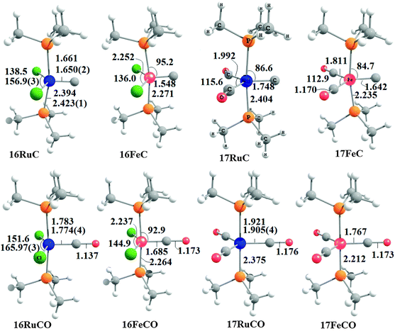 | ||
| Fig. 17 Calculated geometries (BP86/TZ2P) of the carbon complexes 16TMC and 17TMC and the carbonyl complexes 16TMCO and 17TMCO. Bond lengths are given in Å, angles in degree.75 Experimental data are given in italics.2,76a,b The figure has been adapted from ref. 75. | ||
| Molecule | No. | D e (Do) | |
|---|---|---|---|
| BP86/TZ2P | CCSD(T)/TZ2Pa | ||
| a Small-core effective core potential were used for the metals. For details see ref. 73. | |||
| Cl2(PMe3)Ru–C | 16RuC | 146.5 (143.8) | — |
| Cl2(PMe3)Fe–C | 16FeC | 135.1 (132.3) | — |
| (CO)2(PMe3)Ru–C | 17RuC | 100.8 (99.6) | — |
| (CO)2(PMe3)Fe–C | 17FeC | 115.7 (113.6) | — |
| Cl2(PMe3)Ru–CO | 16RuCO | 44.6 (41.2) | — |
| Cl2(PMe3)Fe–CO | 16FeCO | 38.2 (34.7) | — |
| (CO)2(PMe3)Ru–CO | 17RuCO | 40.3 (37.6) | — |
| (CO)2(PMe3)Fe–CO | 17FeCO | 55.3 (51.6) | — |
| (CO)4Ru–C(ax) | 18RuC | 88.8 (88.9) | 93.3 |
| (CO)4Fe–C(ax) | 18FeC | 104.5 (102.7) | 98.6 |
| (CO)4Ru–CO | 18RuCO | 32.5 (30.4) | 32.2 |
| (CO)4Fe–CO | 18FeCO | 46.3 (43.1) | 40.7 |
It is interesting to compare the calculated geometries and bond energies of the carbon complexes 16TMC and 17TMC with the results for the corresponding carbonyl complexes 16TMCO and 17TMCO. Fig. 17 gives for the latter species experimental data of the bond lengths and angles which show that the calculated values are quite accurate. The metal–CO bonds in 16TMCO and 17TMCO are significantly longer and weaker than the metal–C bonds in 16TMC and 17TMC. Table 11 shows that the calculated BDEs of the CO ligand in the former complexes are between De = 38.2 kcal mol−1 (16FeCO) to 55.3 kcal mol−1 (17RuCO) which is much less than the BDEs of the metal–C bonds. Note that the trend of the calculated values for the dissociation energies of the carbonyl complexes 16FeCO < 16RuCO and 17FeCO > 17RuCO is the same as for the carbon complexes 16TMC and 17TMC. The 16VE iron complexes have weaker bonds than the 16VE ruthenium complexes while in the 18VE complexes iron binds stronger than ruthenium. A comparison of the metal–ligand bond lengths in the carbonyl complexes 16TMCO and 17TMCO with the carbon complexes 16TMC and 17TMC indicates that the substitution of the equatorial CO ligand in the former compounds by a carbon ligand elongates the axial but particularly the other equatorial metal–ligand bonds.
Fig. 18 shows the optimized geometries of the carbon complexes [(CO)4TM(C)] (18RuC and 18FeC) and the pentacarbonyls [TM(CO)5] (18RuCO and 18FeCO).75 As noted before, the carbon ligand in 18RuC and 18FeC is in the axial position. The equatorial forms of the latter compounds are not minima on the PES. The TM–C bonds in 18RuC and 18FeC are much shorter and possess a significantly higher BDE (Table 11) than the TM–CO bonds in 18RuCO and 18FeCO. The weakening effect of the carbon ligand on the other CO ligands becomes obvious by the very large trans effect in 18RuC and 18FeC. The calculated Fe–COax bond in 18FeC is very long (1.994 Å) while the interatomic Ru–COax distance in 18RuC (2.477 Å) suggests that the CO ligand is practically dissociated.
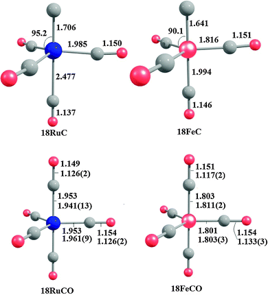 | ||
| Fig. 18 Calculated geometries (BP86/TZ2P) of the carbon complexes 18RuC and 18FeC and the pentacarbonyls 18RuCO and 18FeCO.75 Experimental data are given in italics.76c–e The figure has been adapted from ref. 75. | ||
The central topic of the work by KPF75 is the analysis of the [TM]–C bond and the comparison with the nature of the bonding in metal carbenes [TM]–CR2, carbynes [TM]–CR and carbonyls [TM]–CO. Fig. 19 shows the shape of the most important occupied and vacant MOs of 16RuC which provide via visual inspection a first impression of the nature of the ruthenium–carbon bond. Only those orbitals are displayed which have coefficients at Ru and the ligand carbon atom.
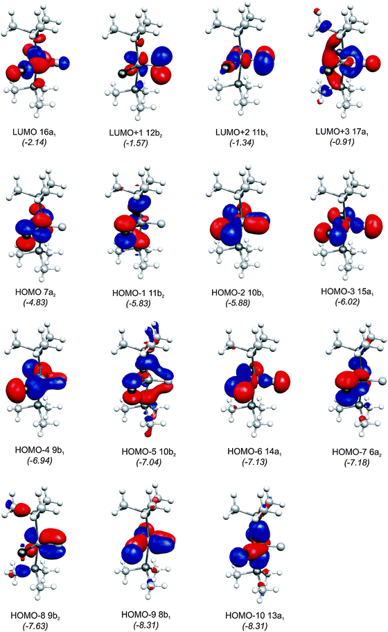 | ||
| Fig. 19 Plot of the ten highest lying occupied molecular orbitals and four lowest lying vacant MOs of [(PMe3)2Cl2Ru(C)] (16RuC). The calculated eigenvalues (BP86/TZ2P) of the orbitals are given in parentheses (in eV).75 The figure has been adapted from ref. 75. | ||
There are seven valence orbitals in 16RuC which contribute to the [Ru]–C bond, two σ orbitals and five π orbitals. The HOMO − 3 (15a1) and HOMO − 6 (14a1) orbitals which come from the bonding and antibonding combination of the dz2 ruthenium orbital with the chlorine p(σ) lone-pair orbitals contribute to the Ru–C σ bond. Two orbitals, i.e. HOMO − 2 (10b1) and HOMO − 9 (8b1) MOs, describe the Ru–C π bonding in the Cl–Ru–Cl plane (π∥). The HOMO − 8 (9b2) orbital is a Ru–C π orbital in the P–Ru–P plane (π⊥). The remaining π orbitals HOMO − 4 (9b1) and HOMO − 5 (10b2) have only small contributions at the carbon ligand atom. Fig. 19 shows also the three lowest lying vacant orbitals of 16RuC. Note that the LUMO (16a1), which has a small coefficient at C, is antibonding with respect to the Ru–C bond. This is important for understanding the changes in the bonding situation of the 18VE complexes where this orbital is occupied and becomes the HOMO. The π orbitals LUMO + 1 (12b2) and LUMO + 2 (11b1) and the occupied σ orbital HOMO − 3 (15a1) are perfectly suited to serve as ligand orbitals for binding of 16RuC to another transition metal fragment. As noted above, the complex [16RuC–Mo(CO)5] where 16RuC binds with Mo(CO)5 through the carbon atom has been synthesized.71
It is interesting to compare the frontier orbitals of the 16VE carbon complex [(PMe3)2Cl2Ru(C)] (16RuC) with the most relevant MOs of the 18VE species [(PMe3)2(CO)2Ru(C)] (17RuC) and with the corresponding CO 16VE complex [(PMe3)2Cl2Ru(CO)] (16RuCO) as well as the 18VE complex [(PMe3)2(CO)2Ru(CO)] (17RuCO). Fig. 20 shows that the HOMO of the 18VE species 17RuC and 17RuCO closely resembles the LUMO of the respective 16VE complexes 16RuCO and 16RuC (Fig. 19). The occupation of the Ru–C and Ru–CO antibonding orbital explains why the bonds in the 18VE compounds are clearly longer than in the 16VE homologues.
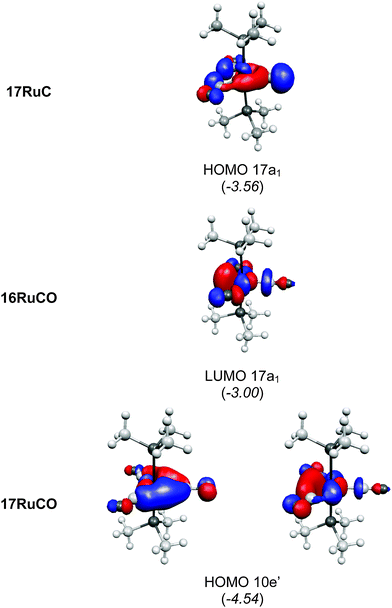 | ||
| Fig. 20 Plot of some relevant molecular orbitals of 17RuC, 16RuCO and 17RuCO. The calculated eigenvalues (BP86/TZ2P) of the orbitals are given in parentheses (in eV).75 The figure has been adapted from ref. 75. | ||
Table 12 summarizes the results of a charge-partitioning analysis of the carbon and CO complexes 16TMC–18TMC and 16TMCO–18TMCO which shed further light on the bonding situation. The calculated values for P(TM-L) suggest that the TM–C bonds have a clearly higher bond order than the TM–CO bonds. Not surprisingly, the 16VE complexes have larger bond orders for the TM–L bonds than the 18VE species. The carbon and CO ligands carry a small positive charge in the 16VE complexes but they are negatively charged in the 18VE species. This indicates that the donor/acceptor ratio of the ligands L = C, CO in the 16VE complexes changes towards more [TM]←L net donation. The latter donation does not reside at the metal atoms. Table 12 shows that the metal atoms in the 16VE complexes are less negatively charged than in the 18VE compounds. The stronger [TM]←L net donation in the former species is conveyed to the CO ligands. We want to point out that the partial charges of the carbon and CO ligands in the 16 and 18VE compounds are not very different from each other. The question remains about the correct description of the [TM]–C interactions. A very detailed answer to this question was given by the EDA results of KPF75 which shall now be summarized.
| Molecule | No. | P(TM–C) | q(TM) | q(C) | q(CO) |
|---|---|---|---|---|---|
| Cl2(PMe3)Ru−C | 16RuC | 2.1 | −0.08 | 0.04 | — |
| Cl2(PMe3)Fe−C | 16FeC | 2.0 | −0.19 | 0.12 | — |
| (CO)2(PMe3)Ru−C | 17RuC | 1.6 | −0.38 | −0.23 | — |
| (CO)2(PMe3)Fe−C | 17FeC | 1.4 | −0.63 | −0.19 | — |
| Cl2(PMe3)Ru−CO | 16RuCO | 1.4 | −0.12 | — | 0.09 |
| Cl2(PMe3)Fe−CO | 16FeCO | 1.2 | −0.07 | — | 0.08 |
| (CO)2(PMe3)Ru−CO | 17RuCO | 0.8 | −0.47 | — | −0.14 |
| (CO)2(PMe3)Fe−CO | 17FeCO | 0.7 | −0.65 | — | −0.10 |
| (CO)4Ru−C | 18RuC | 1.8 | −0.20 | 0.04 | — |
| (CO)4Fe−C | 18FeC | 1.5 | −0.30 | −0.02 | — |
| (CO)4Ru−COeq | 18RuCO | 0.7 | −0.32 | — | 0.02 |
| (CO)4Fe−COeq | 18FeCO | 0.6 | −0.58 | — | 0.08 |
What is the best description for the metal–ligand orbital interactions in the carbon complexes [(PR3)2Cl2Ru(C)], which have been synthesized by Heppert et al.? Fig. 21 shows five different scenarios which are possible for the [TM]–C interactions. Model A sketches the situation which was already mentioned above for (CO)2Fe–C. Here, the carbon atom in the 1D excited state serves as two-electron σ donor while the empty p(π) AOs serve as π acceptors. This is the classical DCD bonding model which is valid for the bonding for metal–CO and Fischer-type metal–carbyne bonds. Model E describes the bonding in terms of three electron-sharing interactions which yield one σ-bond and two π-bonds. The latter description applies to Schrock-type metal carbynes which are better termed metal alkylidynes. Note that the two π bonds in the donor–acceptor model A and the electron-sharing model E are not the same. This is because the ligands in the two planes are different. The plane which contains the chlorine ligands is designated as π∥ while the plane containing the phosphane ligands is designated as π⊥ (see Fig. 21). The orbital models B, C and D describe intermediate cases where one bonding component comes from donor–acceptor interactions while the other two come from electron-sharing bonding.
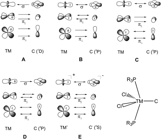 | ||
| Fig. 21 Schematic representation of the electron configurations for the interacting fragments A–E which are used in the EDA calculations of [(PMe3)2Cl2Ru(C)] (16RuC) (Table 13). | ||
The EDA results which are given in Table 13 make it possible to quantitatively estimate the strength of the different orbital interactions which are shown in Fig. 21. The EDA data refer to the instantaneous interactions between the carbon atom and the metal fragment (PMe3)2Cl2Ru which are calculated with the frozen geometry in the complex 16RuC. Five EDA calculations were carried out where the electron configurations of the fragments are chosen in accordance with models A–E.75 Since 16RuC has C2v symmetry there are orbitals with a1(σ), a2(δ), b1(π∥) and b2(π⊥) symmetry which directly relate the calculated values for the orbital terms with the respective orbital interactions that are shown in Fig. 21. But which of the models A–E gives the best description for the orbital interactions in 16RuC? The answer is given by the absolute values of the total orbital interaction term ΔEorb. Those fragment pairs whose orbital relaxation in the final step of the EDA gives the smallest ΔEorb value provide the best description of the interacting species because their electronic structure is closest to the bonding situation in the molecule after bond formation.
![[thin space (1/6-em)]](https://www.rsc.org/images/entities/char_2009.gif) 75
75
| Fragment | A | B | C | D | E |
|---|---|---|---|---|---|
| a The value in parentheses gives the percentage contribution to the total attractive interactions (ΔEElstat + ΔEOrb). b The value in parentheses gives the percentage contribution to the total orbital interactions. | |||||
| ΔEint | −245.0 | −170.4 | −197.9 | −183.4 | −306.9 |
| ΔEPauli | 499.1 | 429.1 | 437.4 | 366.0 | 526.5 |
| ΔEElstata | −410.0 (55.1%) | −289.9 (48.4%) | −301.4 (47.4%) | −183.1 (33.3%) | −493.9 (59.3%) |
| ΔEOrba | −334.1 (44.9%) | −309.6 (51.6%) | −333.9 (52.6%) | −366.3 (66.7%) | −339.6 (40.7%) |
| Δa1(σ)b | −140.1 (41.9%) | −142.0 (45.9%) | −144.9 (43.4%) | −210.5 (57.5%) | −146.6 (43.2%) |
| Δa2(δ)b | −0.2 (0.1%) | −0.3 (0.1%) | −0.3 (0.1%) | −0.4 (0.1%) | −1.7 (0.5%) |
| Δb1(π∥)b | −105.1 (31.5%) | −75.4 (24.4%) | −108.6 (32.5%) | −75.2 (20.5%) | −90.5 (26.7%) |
| Δb2(π⊥)b | −88.8 (26.6%) | −91.9 (29.7%) | −80.2 (24.0%) | −80.3 (21.9%) | −100.8 (29.7%) |
| ΔEPrep | 98.5 | 23.9 | 51.4 | 36.9 | 160.4 |
| −De | −146.5 | −146.5 | −146.5 | −146.5 | −146.5 |
Table 13 shows that the best model for the (PMe3)2Cl2Ru–C bond formation is given by the fragment pair B. According to this model, the metal–carbon bond in 16RuC is a mixture of electron-sharing interactions and donor–acceptor bonding. This makes sense because 16RuC has electron-sharing Ru–Cl bonds as well as donor–acceptor Ru–PR3 bonds. Model B suggests that the Ru–C bond has about one half electrostatic character and one half covalent character. This comes from the EDA values for ΔEelstat and ΔEorb which contribute 48.4% and 51.6% to the total attractive interactions. The orbital interactions ΔEorb come mainly from the electron-sharing σ bond (45.9%). The electron-sharing π∥ bond contributes 24.4% which is somewhat weaker than the donor–acceptor π⊥ bond which contributes 29.7% to ΔEorb. The occurrence of two electron-sharing interactions which comprise one σ and one π bond in the bonding model B (Fig. 21) suggest 16RuC and thus, the isolated carbon complexes2,68,69 are actually Ru(IV) and Os(IV) compounds.
The EDA calculations of the complexes 17RuC–18RuCO revealed that the Ru–C and Ru–CO bonds are better described by model A than model B, because the absolute values for ΔEorb were slightly lower when the former pair of interacting fragments was employed.75 It is therefore appropriate to compare the bonding interactions between the [Ru]–C and [Ru]–CO bonds using the EDA results for model A. Since the carbon and CO ligands in 16RuC–17RuCO are in the equatorial position, KPF optimized (CO)4RuC (18RuC) where C is equatorial ( 18RuC-eq) and analyzed the equatorial Ru–C bond with the EDA method. Structure 18RuC-eq is a transition state but it is the appropriate species for comparison with the equatorial Ru–C and Ru–CO bonds of the other species.
Table 14 shows the EDA results using model A for the equatorial Ru–C and Ru–CO bonds of 16RuC–18RuCO. Note that the equatorial isomer of (CO)4ReC (18RuC-eq) which is 5.2 kcal mol−1 higher in energy than axial 16RuC-ax is not a minimum on the potential energy surface.75 Since the comparison is made for equatorial ligands, 18RuC-eq must be used as the appropriate isomer. The comparison of the 16VE complex pair 16RuC–16RuCO and the 18VE pairs 17RuC–17RuCO as well as 18RuC–18RuCO suggests that the interaction energies of the Ru–C bonds in the carbon complexes 16RuC, 17RuC and 18RuC are much stronger than those of the Ru–CO bonds in 16RuCO, 17RuCO and 18RuCO. This comes from a rather uniform increase of all attractive components of ΔEint: The carbon ligand is a much stronger σ donor as well as a better π acceptor as CO. The σ-donor/π-acceptor ratio is shifted toward greater σ-donor strength and less π acceptor strength of C compared with CO but the overall nature of the Ru–C and Ru–CO bonds does not change dramatically. The EDA results shed light on the question why the 18VE complex 17RuC could not become isolated while the 16VE complex 16RuC is stable in the condensed phase. A comparison of the EDA results using the same model A for both complexes shows (Tables 10 and 11) that the [Ru]–C binding interactions in 17RuC are much weaker than in 16RuC mainly because the a1(σ) contribution which comes from the [Ru]←C donation in the 18VE species is significantly smaller than in the 16VE compound. The much weaker Ru–C σ bonding in 17RuC can be explained with the occupation of the σ antibonding LUMO (16a1) of 16RuC (Fig. 19) which becomes the HOMO in 17RuC (Fig. 20).
![[thin space (1/6-em)]](https://www.rsc.org/images/entities/char_2009.gif) 75
75
| Molecule | 16RuC | 16RuCO | 17RuC | 17RuCO | 18RuC | 18RuCO |
|---|---|---|---|---|---|---|
| Bond | Ru–C | Ru–CO | Ru–C | Ru–CO | Ru–C | Ru–CO |
| a The value in parentheses gives the percentage contribution to the total attractive interactions (ΔEElstat + ΔEOrb). b The value in parentheses gives the percentage contribution to the total orbital interactions. | ||||||
| ΔEint | −245.0 | −98.1 | −184.1 | −52.4 | −159.2 | −42.3 |
| ΔEPauli | 499.1 | 211.8 | 461.1 | 207.2 | 421.9 | 181.0 |
| ΔEElstata | −410.0 (55.1%) | −154.5 (49.9%) | −378.5 (58.7%) | −144.6 (55.7%) | −342.2 (58.9%) | −127.3 (57.0%) |
| ΔEOrba | −334.1 (44.9%) | −155.4 (50.1%) | −266.7 (41.3%) | −115.0 (44.3%) | −238.9 (41.1%) | −96.0 (43.0%) |
| Δa1(σ)b | −140.1 (41.9%) | −68.5 (44.1%) | −95.5 (35.8%) | −48.8 (42.4%) | −101.1 (42.3%) | −49.5 (51.6%) |
| Δa2(δ)b | −0.2 (0.1%) | −0.1 (0.1%) | −0.1 (0.0%) | 0.0 (0.0%) | −0.1 (0.0%) | 0.0 (0.0%) |
| Δb1(π∥)b | −105.1 (31.5%) | −46.7 (30.1%) | −105.4 (39.5%) | −39.4 (34.3%) | −91.9 (38.5%) | −29.8 (31.0%) |
| Δb2(π⊥)b | −88.8 (26.6%) | −40.1 (25.8%) | −65.7 (24.6%) | −26.8 (23.3%) | −45.8 (19.2%) | −16.7 (17.4%) |
| ΔEPrep | 98.5 | 53.5 | 83.3 | 12.1 | 75.5 | 9.8 |
| −De | −146.5 | −44.6 | −100.8 | −40.3 | −83.7 | −32.5 |
The metal–carbon bonding situation in [(PR3)2Cl2Ru(C)] is very similar to the bonding in CO. This finding was pointed out by KPF75 and also by Johnson and co-workers74 in their theoretical studies of carbon complexes. The isolobal77 relationship between carbon complexes and carbon monoxide was the topic of a very detailed theoretical work by Krapp and Frenking (KF).78 These workers calculated the group-8 carbon complexes [(L)2X2TM(C)] for various combinations where L = PH3, PMe3, PPh3, PCy3, NHC and X = F, Cl, Br, I with the metals TM = Fe, Ru, Os which are related to the complexes that have been isolated so far.2,68,69 They also investigated the iron–porphyrin complexes with carbon ligands [(Por)TM(C)] (TM = Fe, Ru, Os; Por = Porphyrin) for which adducts with the Lewis acid Ru2(CO)9 were reported by Beck and co-workers.73 KF calculated the carbon complexes [(L)2X2TM(C)] and [(Por)TM(C)] as well as the adducts with the Lewis acids BH3, BCl3, PdCl2SMe2 and TM(CO)5 (TM = Cr, Mo, W). The latter structures were compared with the corresponding carbonyl complexes. In order to test whether the carbon complexes can also serve as bridging ligands like CO, the authors calculated the complex [Fe2(CO)9] and the analogues molecule [RuCl2(PMe3)2(C)–Fe2(CO)8] where the carbon compound [RuCl2(PMe3)2(C)] binds in the η2-coordination mode. The bonding situation in the compounds was investigated with charge- and energy decomposition methods.78 The most important result will shortly be summarized.
Table 15 shows the calculated bond dissociation energies (BDEs) De of carbon and CO complexes [L–TM(CO)5] (TM = Cr, Mo, W) and the partial charges q(L) of the ligands. It becomes obvious that the BDEs of [(PMe3)2Cl2Ru(C)–TM(CO)5] are nearly the same as for the respective carbonyl adduct [OC–TM(CO)5] and that the partial charges of the L = and the partial charges of the ligands L = [(PMe3)2Cl2Ru(C)] have nearly the same values as for L = OC. The calculated values for the porphyrin substituted carbon complexes [(Por)TM(C)–W(CO)5] (TM = Fe, Ru, Os) indicate somewhat stronger bonds than the other adducts. The carbon complexes [(PMe3)2Cl2Ru(C)] bind a bit stronger to the main group Lewis acids BH3 and BCl3 than CO. The theoretical data support the suggestion that [(PMe3)2Cl2Ru(C)] and OC have similar ligand properties.
![[thin space (1/6-em)]](https://www.rsc.org/images/entities/char_2009.gif) 78
78
| Bond | D e | q(L) |
|---|---|---|
| (PMe3)2Cl2RuC–Cr(CO)5 | 41.6 | 0.29 |
| (PMe3)2Cl2RuC–Mo(CO)5 | 38.9 | 0.20 |
| (PMe3)2Cl2RuC–W(CO)5 | 45.3 | 0.17 |
| (PMe3)2Cl2FeC–W(CO)5 | 45.1 | 0.15 |
| (PMe3)2Cl2OsC–W(CO)5 | 47.1 | 0.20 |
| (PMe3)2F2RuC–W(CO)5 | 39.7 | 0.21 |
| (PMe3)2Br2RuC–W(CO)5 | 44.8 | 0.16 |
| (PMe3)2I2RuC–W(CO)5 | 44.3 | 0.15 |
| (Por)FeC–W(CO)5 | 52.6 | 0.09 |
| (Por)RuC–W(CO)5 | 51.6 | 0.14 |
| (Por)OsC–W(CO)5 | 53.8 | 0.17 |
| (PMe3)2Cl2RuC–BH3 | 47.0 | 0.43 |
| (PMe3)2Cl2RuC–BCl3 | 13.5 | 0.51 |
| OC–Cr(CO)5 | 43.2 | 0.28 |
| OC–Mo(CO)5 | 39.6 | 0.18 |
| OC–W(CO)5 | 45.7 | 0.13 |
| OC–BH3 | 42.6 | 0.39 |
| OC–BCl3 | −6.8 | 0.38 |
Fig. 22 shows the most important frontier orbitals of [(PMe3)2Cl2Ru(C)] and CO. The similarities in the shape of the occupied σ- and π-bonding orbitals and the vacant π* orbitals, which may serve as donor and acceptor orbitals are striking. Fig. 23 displays a selected set of complexes where [(PMe3)2Cl2Ru(C)] and CO are bonded as ligands to the Lewis acids (LAs) W(CO)5, PdCl2SMe2, Fe2(CO)8, BH3 and BCl3. The structures of the complexes are very similar. The complex [(PMe3)2Cl2RuC–Fe2(CO)8] is a minimum on the PES which shows that the carbon complex like CO may bind in an η2-fashion to the Fe2(CO)8. A closer examination of the donor–acceptor bonds in [(PMe3)2Cl2RuC–LA] and [OC–LA] reveals that the carbon complexes exhibit slightly longer C–LA bonds than CO (Fig. 23).
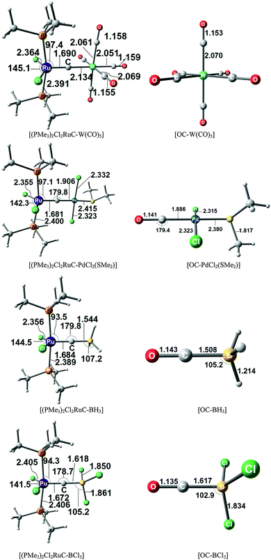 | ||
| Fig. 23 Optimized geometries (BP86/TZVPP) of some carbon and carbonyl complexes. Bond lengths are given in Å, angles in degree.78 The figure has been adapted from ref. 78. | ||
The strongly isolobal relationship between CO and the carbon complexes [TM]C becomes clearly apparent by comparing the EDA results for transition metal complexes which carry CO and [TM]C as ligands. Table 16 shows the EDA results for complexes L–W(CO)5 where L = [TM]C and CO. Four different ligands [TM]C have been chosen, namely [(PMe3)2Cl2Fe(C)], [(PMe3)2Cl2Ru(C)], [(PMe3)2Cl2Os(C)] and the porphyrin species [(Por)RuC]. The calculated data for the different energy terms show the great similarity between [TM]C and CO. The calculated values for the total interaction energy ΔEint between the ligands L and the metal fragment W(CO)5 are very similar. In particular the ΔEint values for the model phosphane ligand (PMe3)2TMCl2 differ by only ∼1 kcal mol−1 from the data for CO. The percentage contributions of electrostatic attraction ΔEelstat and orbital (covalent) interactions ΔEorb to the total attraction of the metal–carbon ligands are also quite similar to the results for CO. The most significant difference concerns the ratio of σ-donation/π-backdonation. The EDA results suggest that (CO)5W→CO π-backdonation is a bit stronger than (CO)5W←CO σ-donation. The opposite trend is calculated for the metal–carbon complexes where the (CO)5W←C[TM] σ-donation is clearly stronger than (CO)5W→C[TM] π-backdonation.78
![[thin space (1/6-em)]](https://www.rsc.org/images/entities/char_2009.gif) 78
78
| (PMe3)2Cl2FeC–W(CO)5 | (PMe3)2Cl2RuC–W(CO)5 | (PMe3)2Cl2OsC–W(CO)5 | (Por)RuC–W(CO)5 | OC–W(CO)5 | |
|---|---|---|---|---|---|
| a Values in parentheses give the percentage contribution to the total attractive interaction (ΔEElstat + ΔEOrb). b Values in parentheses give the percentage contribution to the total orbital interaction (ΔEOrb). | |||||
| ΔEint | −50.9 | −49.7 | −51.1 | −56.2 | −49.7 |
| ΔEPauli | 116.8 | 110.0 | 112.2 | 128.7 | 118.6 |
| ΔEElstata | −89.1 (53.1%) | −85.8 (53.7%) | −92.2 (56.5%) | −99.2 (53.7%) | −89.7 (53.3%) |
| ΔEOrba | −78.6 (46.9%) | −73.9 (46.3%) | −71.1 (43.5%) | −85.6 (46.3%) | −78.6 (46.7%) |
| ΔE(σ)b | −49.2 (62.6%) | −45.8 (62.0%) | −45.5 (63.9%) | −49.3 (57.5%) | −36.3 (46.1%) |
| ΔE(π)b | −29.4 (37.4%) | −28.1 (38.0%) | −25.7 (36.1%) | −36.4 (42.5%) | −42.3 (53.9%) |
5. Transition metal–tetrele complexes [TM]–E (E = Si, Ge, Sn)
The first purposeful synthesis of a transition metal carbene complex in 1964 by Fischer57,58 was soon followed by experimental research with the aim to isolate the heavier group-14 homologues [TM]![[double bond, length as m-dash]](https://www.rsc.org/images/entities/char_e001.gif) ER2 (E = Si–Pb).79 The first examples of stannylene and plumbylene complexes were reported in 1976 by Lappert and co-workers.80 One year later, the first transition metal complex with a germylene ligand could become isolated by the same group.81 The first (unsupported)82 silylene complex which was structurally characterized by X-ray analysis was reported in 1990 by Tilley.83Table 17 shows an overview of the first syntheses of transition metal carbene and carbyne complexes and heavier group-14 homologues. We want to point out that unlike the lighter homologues, until today no X-ray structure for a plumbylene complex has been reported.
ER2 (E = Si–Pb).79 The first examples of stannylene and plumbylene complexes were reported in 1976 by Lappert and co-workers.80 One year later, the first transition metal complex with a germylene ligand could become isolated by the same group.81 The first (unsupported)82 silylene complex which was structurally characterized by X-ray analysis was reported in 1990 by Tilley.83Table 17 shows an overview of the first syntheses of transition metal carbene and carbyne complexes and heavier group-14 homologues. We want to point out that unlike the lighter homologues, until today no X-ray structure for a plumbylene complex has been reported.
![[double bond, length as m-dash]](https://www.rsc.org/images/entities/char_e001.gif) ER2, [TM]
ER2, [TM]![[triple bond, length as m-dash]](https://www.rsc.org/images/entities/char_e002.gif) ER and [TM]
ER and [TM]![[triple bond, length as m-dash]](https://www.rsc.org/images/entities/char_e002.gif) E (E = C–Pb). Literature survey of the first examples of neutral species which – except for the plumbylene complex – were structurally characterized by X-ray analysis
E (E = C–Pb). Literature survey of the first examples of neutral species which – except for the plumbylene complex – were structurally characterized by X-ray analysis
| E | [TM]![[double bond, length as m-dash]](https://www.rsc.org/images/entities/char_e001.gif) ER2 ER2 |
[TM]![[triple bond, length as m-dash]](https://www.rsc.org/images/entities/char_e002.gif) ER ER |
[TM]![[triple bond, length as m-dash]](https://www.rsc.org/images/entities/char_e002.gif) E E |
|---|---|---|---|
| a No X-ray structure available. | |||
| C | E. O. Fischer and A. Maasböl, Angew. Chem., 1964, 76, 645; Angew. Chem., Int. Ed. Engl., 1964, 3, 580. | E. O. Fischer, G. Kreis, C. G. Kreiter, J. Müller, G. Huttner and H. Lorenz, Angew. Chem., 1973, 85, 618; Angew. Chem., Int. Ed., 1973, 12, 564. | R. G. Carlson, M. A. Gile, J. A. Heppert, M. H. Mason, D. R. Powell, D. V. Velde and J. M. Vilain, J. Am. Chem. Soc., 2002, 124, 1580. |
| Si | D. A. Straus, S. D. Grumbine, T. D. Tilley, J. Am. Chem. Soc., 1990, 112, 7801. | A. C. Filippou, O. Chernov, K. W. Stumpf and G. Schnakenburg, Angew. Chem., 2010, 122, 3368; Angew. Chem., Int. Ed., 2010, 49, 3296. | Unknown |
| Ge | M. F. Lappert, S. J. Miles, P. P. Power, A. J. Carty, N. J. Taylor, J. Chem. Soc., Chem. Commun., 1977, 458. | R. S. Simons and P. P. Power, J. Am. Chem. Soc., 1996, 118, 11966. | Unknown |
| Sn | J. D. Cotton, P. J. Davidson and M. F. Lappert, J. Chem. Soc., Dalton Trans., 1976, 2275. | A. C. Filippou, P. Portius, A. I. Philippopoulos and Rohde, H. Angew. Chem., 2003, 115, 461; Angew. Chem., Int. Ed., 2003, 42, 445 | Unknown |
| Pb | J. D. Cotton, P. J. Davidson and M. F. Lappert, J. Chem. Soc., Dalton Trans., 1976, 2275.a | A. C. Filippou, H. Rohde and G. Schnakenburg, Angew. Chem., 2004, 116, 2293; Angew. Chem., Int. Ed., 2004, 43, 2243. | Unknown |
A similar time-delayed history exists for the experimental attempts to synthesis the heavy group-14 homologues of transition metal carbyne complexes.84 Following the first synthesis of a carbyne complex by Fischer in 1973,59 the next member in the series which could become characterized by X-ray analysis was a germylyne complex which was reported by Power in 1996.85 The other three members of the group of heavier carbyne homologues for which X-ray structure analyses have been synthesized by Filippou. The first isolation of a stannylene complex in 200386 was followed by the first synthesis of a plumbylyne complex in 2004.87 Very recently, the first X-ray structure analysis of a silylyne complex was reported by Filippou.88 It is foreseeable that the first synthesis of a carbon complex by Heppert2 in 2002 also triggers intensive efforts to isolate the heavier group-14 homologues [TM]–E. Until today, all attempts have not been successful. This is not surprising when one looks at the history of carbyne homologues where it took 23 years after the work of Fischer before the first heavier homologue could be isolated (Table 17).
Theoretical studies have been published which could be helpful as a guideline for further experimental work. The geometries and bonding situation of the heavier homologues of the model carbon complex [(PMe3)2Cl2TM(E)] (16TME) with TM = Fe, Ru, Os and E = Si, Ge, Sn has been the topic of a quantum chemical investigation by Parameswaran and Frenking (PF1).89 The most important results will shortly be summarized.
Fig. 24 shows the optimized geometries of the 16-electron tetrele complexes 16TME and the calculated BDEs for the (PMe3)2Cl2TM–E bonds with E = C–Sn. The carbon complexes are shown for comparison with the heavier homologues. It becomes obvious that the heavier tetrele complexes have weaker bonds than the lighter ones but even the stannylene complexes have BDEs which are >50 kcal mol−1 which indicates that the TM–Sn bonds are quite strong. The bond orders drops from 2.2 for the Os–C bond to 1.4 for the Fe–Sn bond which suggests a sizeable multiple-bond character. PF1 calculated also the 18-electron complexes [(PR3)2(CO)2TM(E)] (17TME) which exhibit interesting differences compared with the 16-electron species 16TME.89 The optimized geometries and the calculated BDEs for the compounds 17TME are shown in Fig. 25.
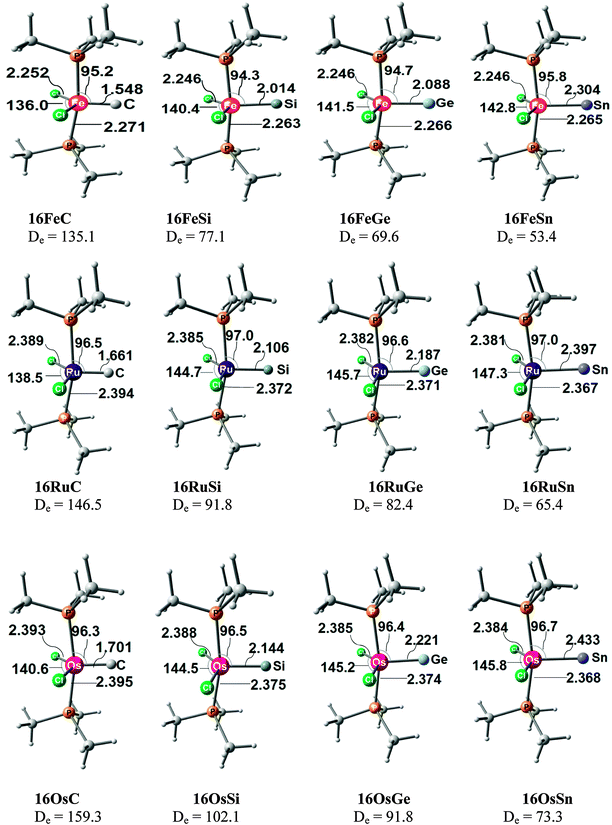 | ||
| Fig. 24 Optimized geometries and TM–E bond dissociation energies De (BP86/TZ2P) of the 16VE tetrele complexes 16TME. Bond lengths are given in Å, angles in degree, energies in kcal mol−1.89 The figure has been adapted from ref. 89. | ||
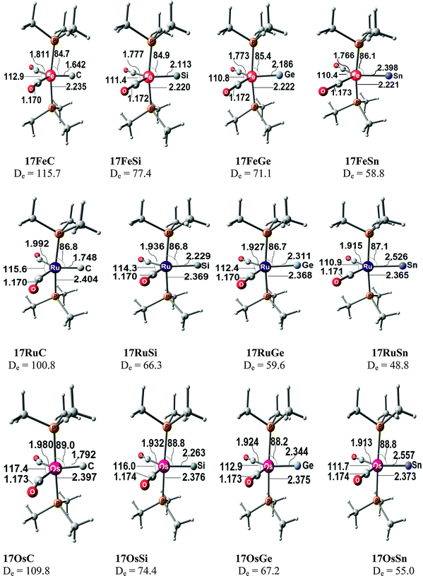 | ||
| Fig. 25 Optimized geometries and TM–E bond dissociation energies De (BP86/TZ2P) of the 18VE tetrele complexes 17TME. Bond lengths are given in Å, angles in degree, energies in kcal mol−1.89 The figure has been adapted from ref. 89. | ||
A comparison of the theoretically predicted TM-E bond lengths and bond orders of the 18-electron complexes 17TME with the 16-electron species 16TME reveals that the former molecules have always longer bonds and smaller bond orders than the latter species. The two series of complexes exhibit distinctively different trends for the bond dissociation energy of the TM–E bond which are shown in Fig. 26. The BDEs of the 16-electron complexes 16TME increase for the heavier transition metals in the order Fe < Ru < Os while the trend for the ligand atoms E is C ≫ Si > Ge > Sn. The latter trend is also calculated for the 18-electron complexes 17TME but the transition metals exhibit the order Ru < Os < Fe. This is the well-known V-shaped sequence for the bond strength of the first, second and third row of transition metals.63b The calculations suggest that iron has the strongest TM–E bond in 17TME while it has the weakest bond in 16TME. This is an important result for experimental studies aiming at the synthesis of 18-electron complexes 17TME.
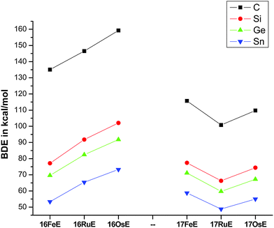 | ||
| Fig. 26 Trend of the calculated bond dissociation energies De (BP86/TZ2P) of the tetrele complexes 16TME and 17TME.89 | ||
The nature of the TM–E bond in 16TME and 17TME has been analyzed by PF189 with the EDA method in order to investigate the changes in the metal–ligand interactions when the tetrele atom becomes heavier. Table 18 shows the results for the ruthenium complexes. The data for the iron and osmium species which were reported by PF1 are not very different from the ruthenium complexes. EDA calculations using the interacting fragments according to bonding models A–E (Fig. 21) showed that the bonding situation in all 16-electron species 16TME is best described by model B while the TM–E bond in the 18-electron complexes 17TME can be described by the classical DCD model which is given by the fragment pair A.75
![[thin space (1/6-em)]](https://www.rsc.org/images/entities/char_2009.gif) 75
75
| 16RuC | 16RuSi | 16RuGe | 16RuSn | 17RuC | 17RuSi | 17RuGe | 17RuSn | |
|---|---|---|---|---|---|---|---|---|
| a The value in parentheses gives the percentage contribution to the total attractive interactions (ΔEElstat + ΔEOrb). b The value in parentheses gives the percentage contribution to the total orbital interactions. | ||||||||
| ΔEint | −170.4 | −113.0 | −103.1 | −85.9 | −184.1 | −117.1 | −108.9 | −93.0 |
| ΔEPauli | 429.1 | 276.4 | 248.8 | 211.9 | 461.1 | 311.9 | 271.9 | 237.5 |
| ΔEElstata | −289.9 (48.4%) | −222.0 (57.0%) | −202.9 (57.7%) | −178.2 (59.8%) | −378.5 (58.7%) | −287.1 (66.9%) | −250.8 (65.9%) | −222.9 (67.4%) |
| ΔEOrba | −309.6 (51.6%) | −167.4 (43.0%) | −149.0 (42.4%) | −119.6 (40.2%) | −266.7 (41.3%) | −141.9 (33.1%) | −129.9 (34.1%) | −107.6 (32.6%) |
| Δa1(σ)b | −142.0 (45.9%) | −79.9 (47.7%) | −73.0 (49.0%) | −61.2 (51.2%) | −95.5 (35.8%) | −66.7 (47.0%) | −62.8 (48.3%) | −55.5 (51.6%) |
| Δa2(δ)b | −0.3 (0.1%) | −0.8 (0.5%) | −0.6 (0.5%) | −0.6 (0.5%) | −0.1 (0.0%) | −0.4 (0.3%) | −0.3 (0.2%) | −0.3 (0.3%) |
| Δb1(π∥)b | −75.4 (24.4%) | −49.1 (29.4%) | −42.9 (28.8%) | −34.0 (28.4%) | −105.4 (39.5%) | −50.0 (35.2%) | −46.3 (35.7%) | −37.5 (34.9%) |
| Δb2(π⊥)b | −91.9 (29.7%) | −37.6 (22.5%) | −32.6 (21.9%) | −23.8 (19.9%) | −65.7 (24.6%) | −24.9 (17.5%) | −20.6 (15.8%) | −14.3 (13.3%) |
| ΔEPrep | 23.9 | 21.2 | 20.8 | 20.5 | 83.3 | 50.8 | 49.2 | 44.2 |
| −De | −146.5 | −91.8 | −82.4 | −65.4 | −100.8 | −66.3 | −59.7 | −48.8 |
The results in Table 18 indicate that the Ru–E bond in 16RuE and 17RuE is less covalent and has a higher electrostatic character when E = Si, Ge, Sn compared with the carbon complexes. The percentage π-backbonding [Ru]←E of the heavier atoms Si–Sn in the 18-electron complexes 17RuE becomes smaller compared with 17RuC which means that the heavier tetrele atoms Si, Ge, Sn are weaker π-acceptors than C. There is an interesting change in the weight of the two components Δb1(π∥) and Δb2(π⊥) to the π-backbonding [Ru]←E for 16RuE and 17RuE. Table 18 shows that the contribution of Δb1(π∥) increases from 16RuE to 17RuE for each atoms E while the strength of Δb2(π⊥) clearly decreases. The Δb1(π∥) orbital interactions in 16RuE come from the electron-sharing π bonds (see Fig. 21, model B) while the Δb1(π∥) term in 17RuE comes from the donor–acceptor π bonds (see Fig. 21, model A). The TM–C π∥ interactions in 16RuE compete with the strongly electron withdrawing TM–chlorine bonds while the TM–C π∥ interactions in 17RuE compete with TM–CO π backdonation. As noted above, the carbon ligand is a much stronger π acceptor than CO. This explains why the Δb1(π∥) contribution to the TM–C bond increases from 16RuE to 17RuE. Note that the intrinsic interaction energies ΔEint in the 18VE complexes 17RuE are larger than in the 16VE species 16RuE (Table 18) but the BDEs of 17RuE are clearly smaller than for 16RuE. This comes from the significantly higher preparation energies ΔEprep in the former species, because the atoms E are in the excited 1D state in the EDA calculations using model A (Fig. 21).
In a second paper by Parameswaran and Frenking (PF2)90 the authors calculated the structures of the adducts 16TME–W(CO)5 and 17TME–W(CO)5 where the tetrele complexes 16TME and 17TME are two-electron donor ligands. The nature of the E–W bonds was investigated with charge- and energy decomposition analyses and the results were compared with the E–W bonds in OE–W(CO)5. The theoretical study could be helpful for the synthesis of the adducts which might be easier than isolating the free tetrele complexes.
Fig. 27 shows the optimized geometries of the complexes 16TME–W(CO)5 which possess a linear coordination at the two coordinated tetrele atom C. A comparison with the structures of the free molecules 16TME (Fig. 24) shows that the TM–E bonds become mostly longer in the adducts 16TME–W(CO)5 but the bond lengthening gets smaller for the heavier atoms E and they become even shorter for the tin complexes and for 16OsGe–W(CO)5. The calculations predict that the TM–PMe3 bonds become always slightly longer in 16TME–W(CO)5 while the TM–Cl bonds become a bit shorter. The E–W distances in 16TME–W(CO)5 may be compared with the calculated E–W bond lengths in OE–W(CO)5 which are shown in Fig. 28. The theoretical data suggest that the OE–W bonds in the latter complexes are clearly shorter than the E–W distances in 16TME–W(CO)5.
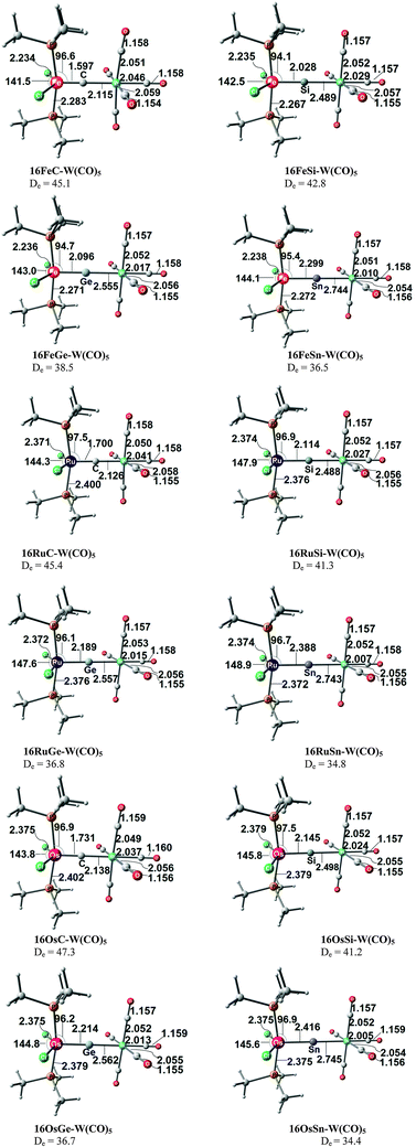 | ||
| Fig. 27 Optimized geometries and E–W bond dissociation energies De (BP86/TZ2P) of the tetrele complexes 16TME–W(CO)5. Bond lengths are given in Å, angles in degree, energies in kcal mol−1.90 The figure has been adapted from ref. 90. | ||
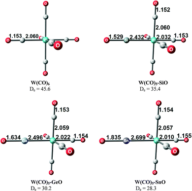 | ||
| Fig. 28 Optimized geometries and E–W bond dissociation energies De (BP86/TZ2P) of the complexes OE–W(CO)5. Bond lengths are given in Å, angles in degree, energies in kcal mol−1.90 The figure has been adapted from ref. 90. | ||
The calculated bond energies indicate that the E–W bonds in 16TME–W(CO)5 are rather strong. The theoretically predicted BDEs of the carbon complexes 16TMC–W(CO)5 (De = 45.1–47.3 kcal mol−1) have very similar values as the BDE of W(CO)6 (De = 45.6 kcal mol−1) while the heavier homologues 16TME–W(CO)5 (E = Si–Sn) possess BDEs which are clearly larger than those of the respective molecule OE–W(CO)5.
Fig. 29 shows the optimized geometries of the complexes 17TME–W(CO)5 which exhibit also a linear coordination mode at the tetrele atom E. There is an interesting difference in the geometry alteration of the ligand species 17TME relative to 16TME. The TM–C bond becomes significantly longer in 17TMC–W(CO)5 but the TM–E bonds of the heavier homologues 17TME–W(CO)5 where E = Si–Sn become always shorter than in 17TME. Note that the E–W bond lengths in 17TME–W(CO)5 are not very different from those in 16TME–W(CO)5 but the former complexes have clearly higher BDEs (Fig. 29) than the latter (Fig. 27). It is well known that bond lengths and bond strength do not necessarily correlate.91
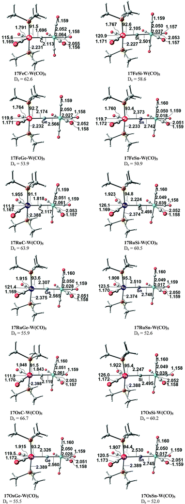 | ||
| Fig. 29 Optimized geometries and E–W bond dissociation energies De (BP86/TZ2P) of the tetrele complexes 17TME–W(CO)5. Bond lengths are given in Å, angles in degree, energies in kcal mol−1.90 | ||
PF290 calculated some reaction energies which indicate the possible stabilities of the adducts 16TME–W(CO)5 and 17TME–W(CO)5. The theoretical data for reactions 1 and 2 (Table 19) predict that substituting a CO ligand in W(CO)6 by a 16VE tetrele complex 16TME is energetically unfavourable except for 16OsC while the substitution reaction of one CO in W(CO)6 by 17TME is endothermic with the trend C > Si > Ge > Sn. The heavier tetrele complexes 16TME and 17TME (E = Si–Sn) are always much more strongly bonded to W(CO)5 than the diatomic species EO (reactions (3) and (4)).
| TM | E | ΔE(1) | ΔE(2) | ΔE(3) | ΔE(4) |
|---|---|---|---|---|---|
| Fe | C | 0.7 | −16.7 | 0.7 | −16.7 |
| Si | 2.8 | −13.0 | −7.4 | −23.2 | |
| Ge | 7.0 | −8.4 | −8.3 | −23.7 | |
| Sn | 9.0 | −5.4 | −8.2 | −22.6 | |
| Ru | C | 0.4 | −18.0 | 0.4 | −18.0 |
| Si | 4.2 | −15.0 | −6.0 | −25.2 | |
| Ge | 8.7 | −10.4 | −6.6 | −25.7 | |
| Sn | 10.8 | −7.1 | −6.5 | −24.3 | |
| Os | C | −1.5 | −20.9 | −1.5 | −20.9 |
| Si | 4.3 | −14.7 | −5.9 | −24.9 | |
| Ge | 8.8 | −10.0 | −6.5 | −25.3 | |
| Sn | 11.1 | −6.5 | −6.1 | −23.7 | |
| 16TME + W(CO)6 → 16TME–W(CO)5 + CO — (1) |
| 17TME + W(CO)6 → 17TME–W(CO)5 + CO — (2) |
| 16TME + (CO)5W-EO → 16TME–W(CO)5 + EO — (3) |
| 17TME + (CO)5W-EO → 17TME–W(CO)5 + EO — (4) |
The nature of the E–W bonds in 16TME–W(CO)5 and 17TME–W(CO)5 was analyzed by PF290 with the EDA method. Table 20 gives the results for the ruthenium complexes 16RuE–W(CO)5 and 17RuE–W(CO)5 and for OE–W(CO)5. The data indicate that the nature of the bonding is not very different from each other. The covalent character of the bonds which is given by the percentage values of ΔEorb in the tetrele complexes 16TME–W(CO)5 is nearly the same as in OE–W(CO)5 while it is somewhat smaller in 17TME–W(CO)5. All ligands 16RuE, 17RuE and OE are stronger σ donors than π acceptors except CO which is calculated to be a stronger π acceptor.92
![[thin space (1/6-em)]](https://www.rsc.org/images/entities/char_2009.gif) 90
90
| 16RuC–W(CO)5 | 16RuSi–W(CO)5 | 16RuGe–W(CO)5 | 16RuSn–W(CO)5 | 17RuC–W(CO)5 | 17RuSi–W(CO)5 | 17RuGe–W(CO)5 | 17RuSn–W(CO)5 | OC–W(CO)5 | OSi–W(CO)5 | OGe–W(CO)5 | OSn–W(CO)5 | |
|---|---|---|---|---|---|---|---|---|---|---|---|---|
| a The value in parentheses gives the percentage contribution to the total attractive interactions (ΔEElstat + ΔEOrb). b The value in parentheses gives the percentage contribution to the total orbital interactions. | ||||||||||||
| ΔEint | −49.3 | −43.4 | −38.5 | −36.2 | −71.7 | −66.9 | −61.2 | −58.0 | −49.7 | −37.7 | −32.2 | −29.9 |
| ΔEPauli | 113.0 | 103.4 | 87.7 | 77.3 | 163.2 | 153.1 | 130.7 | 120.0 | 118.6 | 94.0 | 79.8 | 72.6 |
| ΔEElstata | −87.3 (53.8%) | −78.3 (53.3%) | −67.0 (53.1%) | −59.5 (52.5%) | −146.9 (62.5%) | −137.8 (62.7%) | −118.7 (61.9%) | −109.8 (61.7%) | −89.6(53.3%) | −63.9 (48.5%) | −54.3 (48.5%) | −52.7 (51.4%) |
| ΔEOrba | −75.0 (46.2%) | −68.5 (46.7%) | −59.2 (46.9%) | −53.9 (47.5%) | −88.0 (37.5%) | −82.2 (37.4%) | −73.2 (38.1%) | −68.3 (38.3%) | −78.6 (46.7%) | −67.9 (51.5%) | −57.7 (51.5%) | −49.8 (48.6%) |
| Δa1(σ)b | −46.3 (61.7%) | −47.2 (68.9%) | −43.2 (72.9%) | −41.9 (77.7%) | −54.8 (62.3%) | −60.4 (73.5%) | −55.6 (76.0%) | −54.5 (79.9%) | −36.3 (46.1%) | −37.3 (54.9%) | −34.1 (59.1%) | −33.1 (66.5%) |
| Δa2(δ)b | −0.3 (0.3%) | −0.1 (0.1%) | −0.0 (0.0%) | −0.0 (0.1%) | −0.6 (0.7%) | −0.2 (0.2%) | −0.1 (0.2%) | −0.1 (0.2%) | −0.0 (0.0%) | −0.3 (0.4%) | −0.2 (0.3%) | −0.2 (0.3%) |
| Δb1(π∥)b | −13.4 (17.8%) | −10.0 (14.6%) | −7.4 (12.5%) | −5.5 (10.1%) | −13.5 (15.4%) | −9.9 (12.1%) | −7.8 (10.6%) | −6.1 (9.0%) | −21.2 (26.9%) | −15.2 (22.4%) | −11.7 (20.3%) | −8.3 (16.6%) |
| Δb2(π⊥)b | −15.1 (20.2%) | −11.3 (16.4%) | −8.6 (14.5%) | −6.5 (12.1%) | −19.1 (21.7%) | −11.7 (14.2%) | −9.7 (13.2%) | −7.5 (11.0%) | −21.2 (26.9%) | −15.2 (22.4%) | −11.7 (20.3%) | −8.3 (16.6%) |
| ΔEPrep | 3.9 | 2.1 | 1.7 | 1.4 | 7.8 | 6.4 | 5.2 | 5.4 | 4.0 | 2.4 | 2.1 | 1.6 |
| −De | −45.4 | −41.3 | −36.8 | −34.8 | −63.9 | −60.5 | −55.9 | −52.6 | −45.6 | −35.4 | −30.2 | −28.3 |
6. Summary and conclusion
The theoretical work which is reviewed here shows that the naked group-14 atoms E = C–Pb in the singlet 1D state behave as bidentate Lewis acids which strongly bind two σ donor ligands L in the donor–acceptor complexes L→E←L. Tetrylones EL2 are divalent E(0) compounds which possess two lone pairs at E. The unique electronic structure of tetrylones (carbones, silylones, germylones, stannylones, plumbylones) clearly distinguishes them from tetrylenes ER2 (carbenes, silylenes, germylenes, stannylenes, plumbylenes) which have electron-sharing bonds R–E–R and only one lone pair at atom E. The different electronic structures of tetrylones and tetrylenes are revealed by charge- and energy decomposition analyses they become obvious by a distinctively different chemical reactivity. The unusual structures and chemical behaviour of tetrylones EL2 can be understood in terms of the donor–acceptor interactions L→E←L. Tetrylones are potential donor ligand in main group compounds and transition metal complexes which are experimentally not yet known. The theoretical studies which are presented and discussed in this review provide an outlook over a wide area which awaits to be explored.The second part of the review introduces theoretical studies of transition metal complexes [TM]–E which carry naked tetrele atoms E = C–Sn as ligands. The bonding analyses suggest that the group-14 atoms bind in the 3P reference state to the transition metal in a combination of σ and π∥ electron-sharing bonds TM–E and π⊥ backdonation TM→E. The unique bonding situation of the tetrele complexes [TM]–E makes them suitable ligands in adducts with Lewis acids. Theoretical studies of [TM]–E→W(CO)5 predict that such species may becomes synthesized. This is also a large field of promising experimental research which awaits to become explored.
Acknowledgements
This work was supported by the Deutsche Forschungsgemeinschaft and by the Alexander von Humboldt Foundation.References
- F. Ramirez, N. B. Desai, B. Hansen and N. McKelvie, J. Am. Chem. Soc., 1961, 83, 3539 CrossRef CAS.
- R. G. Carlson, M. A. Gile, J. A. Heppert, M. H. Mason, D. R. Powell, D. V. Velde and J. M. Vilain, J. Am. Chem. Soc., 2002, 124, 1580 CrossRef CAS PubMed.
- G. Frenking, C. Loschen, A. Krapp, S. Fau and S. H. Strauss, J. Comput. Chem., 2007, 28, 117 CrossRef CAS PubMed.
- We use the term valence as indicator for the number of chemical bonds while the oxidation state which is given in parentheses gives the number of valence electrons which is used for chemical bonding. Thus, tetravalent carbon(IV) employs four valence electrons for four bonds, divalent carbon(II) uses two valence electrons for two bonds while two electrons remain as lone-pair. Divalent carbon(0) compounds have two lone-pairs and two donor–acceptor bonds.
- A. Igau, H. Grützmacher, A. Baceiredo and G. Bertrand, J. Am. Chem. Soc., 1988, 110, 6463 CrossRef CAS.
- A. J. Arduengo III, R. L. Harlow and M. Kline, J. Am. Chem. Soc., 1991, 113, 2801 CrossRef.
- (a) W. Kirmse, Angew. Chem., 2004, 116, 1799 CrossRef; W. Kirmse, Angew. Chem., Int. Ed., 2004, 43, 1767 Search PubMed; (b) D. Martin, M. Melaimi, M. Soleilhavoup and G. Bertrand, Organometallics, 2011, 30, 5304 CrossRef CAS PubMed; (c) O. Kaufhold and F. E. Hahn, Angew. Chem., 2008, 120, 4122 CrossRef; O. Kaufhold and F. E. Hahn, Angew. Chem., Int. Ed., 2008, 47, 4057 Search PubMed; (d) P. L. Arnold and S. Pearson, Coord. Chem. Rev., 2007, 251, 596 CrossRef CAS PubMed; (e) M. Albrecht, Chem. Commun., 2008, 3601 RSC; (f) O. Schuster, L. Yang, H. G. Raubenheimer and M. Albrecht, Chem. Rev., 2009, 109, 3445 CrossRef CAS PubMed; (g) M. Albrecht, Chimia, 2009, 63, 105 CrossRef CAS; (h) M. Iglesias and M. Albrecht, Dalton Trans., 2010, 39, 5213 RSC.
- N-Heterocyclic Carbenes in Transition Metal Catalysis, ed. F. Glorius, Springer, Berlin, 2007 Search PubMed.
- Recent reviews: (a) A. J. Arduengo III, Acc. Chem. Res., 1999, 32, 913 CrossRef; (b) D. Bourissou, O. Guerret, F. P. Gabbaï and G. Bertrand, Chem. Rev., 2000, 100, 39 CrossRef CAS PubMed; (c) W. A. Herrmann, Angew. Chem., Int. Ed., 2002, 41, 1290 CrossRef CAS; (d) N-Heterocyclic Carbenes in Synthesis, ed. S. P. Nolan, Wiley-VCH, Weinheim, Germany, 2006 Search PubMed; (e) E. Peris and R. H. Crabtree, Coord. Chem. Rev., 2004, 248, 2239 CrossRef CAS PubMed; (f) C. M. Crudden and D. P. Allen, Coord. Chem. Rev., 2004, 248, 2247 CrossRef CAS PubMed; (g) S. Díez-González and S. P. Nolan, Coord. Chem. Rev., 2007, 251, 874 CrossRef PubMed; (h) E. A. B. Kantchev, C. J. O’Brien and M. G. Organ, Angew. Chem., 2007, 119, 2824 CrossRef; E. A. B. Kantchev, C. J. O’Brien and M. G. Organ, Angew. Chem., Int. Ed., 2007, 46, 2768 Search PubMed; (i) F. E. Hahn and M. C. Jahnke, Angew. Chem., Int. Ed., 2008, 47, 3122 CrossRef CAS PubMed; (j) S. Würtz and F. Glorius, Acc. Chem. Res., 2008, 41, 1523 CrossRef PubMed; (k) S. Díez-González, N. Marion and S. P. Nolan, Chem. Rev., 2009, 109, 3612 CrossRef PubMed; (l) R. Wolf and W. Uhl, Angew. Chem., Int. Ed., 2009, 48, 6774 CrossRef CAS PubMed; (m) T. Dröge and F. Glorius, Angew. Chem., Int. Ed., 2010, 49, 6940 CrossRef PubMed; (n) M. Melaimi, M. Soleilhavoup and G. Bertrand, Angew. Chem., Int. Ed., 2010, 49, 8810 CrossRef CAS PubMed.
- V. Kaufman and J. F. Ward, J. Opt. Soc. Am., 1966, 56, 1591 CrossRef CAS.
- G. Frenking and R. Tonner, Pure Appl. Chem., 2009, 81, 597 CrossRef CAS.
- (a) W. Petz and G. Frenking, Top. Organomet. Chem., 2010, 30, 49 CrossRef CAS; (b) N. D. Jones and R. G. Cavell, J. Organomet. Chem., 2005, 690, 5485 CrossRef CAS PubMed; (c) O. I. Kolodiazhnyi, Phosphorous Ylides: Chemistry and Application in Organic Synthesis, Wiley-VCH, Weinheim, 1999 Search PubMed; (d) O. I. Kolodiazhnyi, Tetrahedron, 1996, 52, 1855 CrossRef CAS; (e) Ylides and Imines of Phosphorus, ed. A. W. Johnson, Wiley&Sons, New York, 1993 Search PubMed; (f) H. Schmidbaur, Angew. Chem., 1983, 95, 980 CrossRef CAS; H. Schmidbaur, Angew. Chem., Int. Ed. Engl., 1983, 22, 907 Search PubMed.
- G. E. Hardy, J. I. Zink, W. C. Kaska and J. C. Baldwin, J. Am. Chem. Soc., 1978, 100, 8002 CrossRef.
- R. Tonner and G. Frenking, Chem. – Eur. J., 2008, 14, 3260 CrossRef CAS PubMed.
- There are no genuine σ and π orbitals in C(PPh3)2 because the molecular geometry has no mirror plane. However, the shape of the orbitals easily identifies them as σ- and π-type with respect to the local P–C–P plane.
- R. Tonner, F. Öxler, B. Neumüller, W. Petz and G. Frenking, Angew. Chem., 2006, 118, 8206 CrossRef CAS; R. Tonner, F. Öxler, B. Neumüller, W. Petz and G. Frenking, Angew. Chem., Int. Ed., 2006, 45, 8038 CrossRef PubMed.
- C. Kaska, D. K. Mitchell and R. F. Reichelderfer, J. Organomet. Chem., 1973, 47, 391 CrossRef.
- W. Petz, C. Kutschera, M. Heitbaum, G. Frenking, R. Tonner and B. Neumüller, Inorg. Chem., 2005, 44, 1263 CrossRef CAS PubMed.
- R. Tonner, G. Heydenrych and G. Frenking, ChemPhysChem, 2008, 9, 1474 CrossRef CAS PubMed.
- W. Petz, F. Öxler, B. Neumüller, R. Tonner and G. Frenking, Eur. J. Inorg. Chem., 2009, 4507 CrossRef CAS.
- B. Inés, M. Patil, J. Carreras, R. Goddard, W. Thiel and M. Alcarazo, Angew. Chem., Int. Ed., 2011, 50, 8400 CrossRef PubMed.
- J. J. Daly and P. Wheatley, J. Chem. Soc., 1966, 1703 RSC.
- O. Diels and B. Wolf, Ber. Dtsch. Chem. Ges., 1906, 39, 689 CrossRef.
- J. Koput, Chem. Phys. Lett., 2000, 320, 237 CrossRef CAS . The value for the C–C–C bending angle stems from a high-level quantum chemical calculation at CCSD(T)/cc-pVQZ which predicts that the barrier to linearity is only 18 cm−1. This is in agreement with the high-resolution infrared spectrum of C3O2 which suggests that the molecule is quasi-linear: J. Vander Auwera, J. W. C. Johns and O. L. Polyansky, J. Chem. Phys., 1991, 95, 2299 CrossRef PubMed.
- (a) R. Tonner and G. Frenking, Angew. Chem., 2007, 119, 8850 CrossRef; R. Tonner and G. Frenking, Angew. Chem., Int. Ed., 2007, 46, 8695 Search PubMed; (b) G. Frenking and R. Tonner, Wiley Interdiscip. Rev.: Comput. Mol. Sci., 2011, 1, 869 CrossRef CAS; (c) G. Frenking and R. Tonner, in Contemporary Carbene Chemistry, ed. R. A. Moss and M. P. Doyle, Wiley, New Jersey, 2013, p. 167 Search PubMed.
- C. A. Dyker, V. Lavallo, B. Donnadieu and G. Bertrand, Angew. Chem., 2008, 120, 3250 CrossRef CAS; C. A. Dyker, V. Lavallo, B. Donnadieu and G. Bertrand, Angew. Chem., Int. Ed., 2008, 47, 3206 CrossRef PubMed.
- A. Fürstner, M. Alcarazo, R. Goddard and C. W. Lehmann, Angew. Chem., 2008, 120, 3254 CrossRef; A. Fürstner, M. Alcarazo, R. Goddard and C. W. Lehmann, Angew. Chem., Int. Ed., 2008, 47, 3210 CrossRef PubMed.
- M. Alcarazo, W. Lehmann, A. Anoop, W. Thiel and A. Fürstner, Nat. Chem., 2009, 1, 295 CrossRef CAS PubMed.
- M. J. Taylor, P. W. J. Surman and G. R. Clark, J. Chem. Soc., Chem. Commun., 1994, 2517 RSC.
- H. G. Viehe, Z. Janousek, R. Gompper and D. Lach, Angew. Chem., 1973, 85, 581 CrossRef CAS; H. G. Viehe, Z. Janousek, R. Gompper and D. Lach, Angew. Chem., Int. Ed. Engl., 1973, 12, 566 CrossRef.
- R. Tonner and G. Frenking, Chem. – Eur. J., 2008, 14, 3273 CrossRef CAS PubMed.
- S. Klein, R. Tonner and G. Frenking, Chem. – Eur. J., 2010, 16, 10160 CrossRef CAS PubMed.
- C. A. Dyker and G. Bertrand, Nat. Chem., 2009, 1, 265 CrossRef CAS PubMed.
- (a) C. A. Dyker, V. Lavallo, B. Donnadieu and G. Bertrand, Angew. Chem., 2008, 120, 3250 CrossRef; C. A. Dyker, V. Lavallo, B. Donnadieu and G. Bertrand, Angew. Chem., Int. Ed., 2008, 47, 3206 Search PubMed; (b) I. Fernandez, C. A. Dyker, A. DeHope, B. Donnadieu, G. Frenking and G. Bertrand, J. Am. Chem. Soc., 2009, 131, 11875 CrossRef CAS PubMed.
- (a) J.-M. Sotiropoulos, A. Baceiredo and G. Bertrand, J. Am. Chem. Soc., 1987, 109, 4711 CrossRef CAS; (b) N. DubauAssibat, A. Baceiredo, F. Dahan and G. Bertrand, Bull. Soc. Chim. Fr., 1995, 132, 1139 CAS; (c) J.-M. Sotiropoulos, A. Baceiredo and G. Bertrand, Bull. Soc. Chim. Fr., 1992, 129, 367 CAS.
- K. Morokuma, J. Chem. Phys., 1971, 55, 1236 CrossRef CAS PubMed.
- (a) T. Ziegler and A. Rauk, Inorg. Chem., 1979, 18, 1755 CrossRef CAS; (b) T. Ziegler and A. Rauk, Inorg. Chem., 1979, 18, 1558 CrossRef CAS.
- M. Mitoraj and A. Michalak, Organometallics, 2007, 26, 6576 CrossRef CAS.
- (a) A. Michalak, M. Mitoraj and T. Ziegler, J. Phys. Chem. A, 2008, 112, 1933 CrossRef CAS PubMed; (b) M. P. Mitoraj, A. Michalak and T. Ziegler, J. Chem. Theory Comput., 2009, 5, 962 CrossRef CAS.
- (a) F. M. Bickelhaupt and E. J. Baerends, in Rev. Comput. Chem, ed. K. B. Lipkowitz and D. B. Boyd, Wiley-VCH, Inc., New York, 2000, vol. 15, p. 1 Search PubMed; (b) M. Lein and G. Frenking, in Theory and Applications of Computational Chemistry: The First 40 Years, ed. C. E. Dykstra, G. Frenking and K. S. Kim and G. E. Scuseria, Elsevier, Amsterdam, 2005, p. 367 Search PubMed; (c) M. von Hopffgarten and G. Frenking, Wiley Interdiscip. Rev.: Comput. Mol. Sci., 2012, 2, 43 CrossRef CAS; (d) G. Frenking and F. M. Bickelhaupt, in The Chemical Bond: Fundamental Aspects of Chemical Bonding, ed. G. Frenking and S. Shaik, Wiley-VCH, Weinheim, 2014, pp. 121–157 Search PubMed.
- We are using the term tetrele as shortform expression for group-14 atoms C–Pb which has been suggested earlier for elements of the fourth (“tetra”) main group.
- A bonding situation with donor–acceptor bonds between bare group-14 atoms Si and Ge and a diazabutadiene ligand has earlier been discussed for N-heterocyclic silylene and germylene by Arduengo et al. who called it “…doubtless an extreme exaggeration of the bonding…”: A. J. Arduengo, H. Bock, H. Chen, M. Denk, D. A. Dixon, J. C. Green, W. A. Herrmann, N. L. Jones, M. Wagner and R. West, J. Am. Chem. Soc., 1994, 116, 6641 CrossRef CAS.
- (a) S. Ishida, T. Iwamoto, C. Kabuto and M. Kira, Nature, 2003, 421, 725 CrossRef CAS PubMed; (b) T. Iwamoto, H. Masuda, C. Kabuto and M. Kira, Organometallics, 2005, 24, 197 CrossRef CAS.
- M. Kosa, M. Karni and Y. Apeloig, J. Chem. Theory Comput., 2006, 2, 956 CrossRef CAS.
- (a) T. Veszprémi, A. Olasz and B. Pintér, Silicon Chem., 2006, 3, 187 CrossRef PubMed; (b) T. Veszprémi, K. Petrov and C. T. Nguyen, Organometallics, 2006, 25, 1480 CrossRef; (c) K. T. Petrov and T. Veszprémi, Int. J. Chem. Model., 2008, 1, 1 Search PubMed; (d) K. T. Petrov and T. Veszprémi, Int. J. Quantum Chem., 2009, 109, 2526 CrossRef CAS.
- (a) J. S. Binkley, J. Am. Chem. Soc., 1984, 106, 603 CrossRef CAS; (b) J. Kalcher, A. Sax and G. Olbrich, Int. J. Quantum Chem., 1984, 25, 543 CrossRef CAS; (c) H.-J. Köhler and H. Lischka, Chem. Phys. Lett., 1984, 112, 33 CrossRef; (d) D. A. Clabo and H. F. Schaefer, J. Chem. Phys., 1986, 84, 1664 CrossRef CAS PubMed; (e) B. S. Thies, R. S. Grev and H. F. Schaefer, Chem. Phys. Lett., 1987, 140, 355 CrossRef CAS; (f) S. Koseki and M. S. Gordon, J. Phys. Chem., 1988, 92, 364 CrossRef CAS; (g) S. Koseki and M. S. Gordon, J. Phys. Chem., 1989, 93, 118 CrossRef CAS; (h) B. T. Colegrove and H. F. Schaefer, J. Phys. Chem., 1990, 94, 5593 CrossRef CAS; (i) B. T. Colegrove and H. F. Schaefer, J. Am. Chem. Soc., 1991, 113, 1557 CrossRef CAS; (j) R. S. Grev and H. F. Schaefer, J. Chem. Phys., 1992, 97, 7990 CrossRef CAS PubMed; (k) R. S. Grev, B. J. De Leeuw and H. F. Schaefer, Chem. Phys. Lett., 1990, 165, 257 CrossRef CAS; (l) R. S. Grev, Adv. Organomet. Chem., 1991, 33, 125 CrossRef CAS; (m) Z. Palagyi, H. F. Schaefer and E. Kapuy, J. Am. Chem. Soc., 1993, 115, 6901 CrossRef CAS; (n) Q.-S. Li, R.-H. Lü, Y. Xie and H. F. Schaefer, J. Comput. Chem., 2002, 23, 1642 CrossRef CAS PubMed; (o) S. Nagase, K. Kobayashi and N. Takagi, J. Organomet. Chem., 2000, 611, 264 CrossRef CAS; (p) Y.-K. Han, C. Bae, Y. S. Lee and S. Y. Lee, J. Comput. Chem., 1998, 19, 1526 CrossRef CAS.
- M. Lein, A. Krapp and G. Frenking, J. Am. Chem. Soc., 2005, 127, 6290 CrossRef CAS PubMed.
- A. E. Reed, L. A. Curtiss and F. Weinhold, Chem. Rev., 1988, 88, 899 CrossRef CAS.
- N. Wiberg, H.-W. Lerner, S.-K. Vasisht, S. Wagner, K. Karaghiosoff, H. Nöth and W. Ponikwar, Eur. J. Inorg. Chem., 1999, 1211 CrossRef CAS.
- (a) N. Takagi, T. Shimizu and G. Frenking, Chem. – Eur. J., 2009, 15, 3448 CrossRef CAS PubMed; (b) N. Takagi, T. Shimizu and G. Frenking, Chem. – Eur. J., 2009, 15, 8593 CrossRef CAS PubMed; (c) N. Takagi and G. Frenking, Theor. Chem. Acc., 2011, 129, 615 CrossRef CAS.
- (a) G. Trinquier and J.-P. Malrieu, J. Am. Chem. Soc., 1987, 109, 5303 CrossRef CAS; (b) G. Trinquier and J.-P. Malrieu, J. Am. Chem. Soc., 1989, 111, 5916 CrossRef; (c) E. A. Carter and W. A. Goddard, J. Phys. Chem., 1986, 90, 998 CrossRef CAS; (d) For a discussion of the bonding model see: M. Driess and H. Grützmacher, Angew. Chem., 1996, 108, 900 CrossRef; M. Driess and H. Grützmacher, Angew. Chem Int. Ed., 1996, 35, 828 Search PubMed.
- N. Takagi, R. Tonner and G. Frenking, Chem. – Eur. J., 2012, 18, 1772 CrossRef CAS PubMed.
- T. A. N. Nguyen and G. Frenking, Chem. – Eur. J., 2012, 18, 12733 CrossRef CAS PubMed.
- (a) K. C. Mondal, H. W. Roesky, F. Klinke, M. C. Schwarzer, G. Frenking, B. Niepötter, H. Wolf, R. Herbst-Irmer and D. Stalke, Angew. Chem., 2013, 125, 3036 CrossRef; K. C. Mondal, H. W. Roesky, F. Klinke, M. C. Schwarzer, G. Frenking, B. Niepötter, H. Wolf, R. Herbst-Irmer and D. Stalke, Angew. Chem., Int. Ed., 2013, 52, 2963 Search PubMed; (b) Y. Li, K. C. Mondal, H. W. Roesky, H. Zhu, P. Stollberg, R. Herbst-Irmer, D. Stalke and D. M. Andrade, J. Am. Chem. Soc., 2013, 135, 12422 CrossRef CAS PubMed.
- (a) Y. Xiong, S. Yao, S. Inoue, J. D. Epping and M. Driess, Angew. Chem., 2013, 125, 7287 CrossRef; Y. Xiong, S. Yao, S. Inoue, J. D. Epping and M. Driess, Angew. Chem., Int. Ed., 2013, 52, 7147 Search PubMed; (b) Y. Xiong, S. Yao, S. Inoue, J. D. Epping and M. Driess, Angew. Chem., 2013, 125, 7287 CrossRef; Y. Xiong, S. Yao, S. Inoue, J. D. Epping and M. Driess, Angew. Chem., Int. Ed., 2013, 52, 7147 Search PubMed.
- C. Elschenbroich, Organometallics, Wiley-VCH, Weinheim, 3rd edn, 2006 Search PubMed.
- E. O. Fischer and A. Maasböl, Angew. Chem., 1964, 76, 645 CrossRef CAS; E. O. Fischer and A. Maasböl, Angew. Chem., Int. Ed. Engl., 1964, 3, 580 CrossRef.
- The first synthesis of a carbene complex is usually associated with the work of Fischer and Maasböl in 1964 (ref. 57). Prior to this work, carbene complexes were already synthesized much earlier by Tschugajeff: (a) L. Tschugajeff and M. Skanawy-Grigorjewa, J. Russ. Chem. Soc., 1915, 47, 776 Search PubMed; (b) L. Tschugajeff, M. Skanawy-Grigorjewa and A. Posnjak, Z. Anorg. Chem., 1925, 148, 37 CrossRef . However, the authors did not identify the compounds as carbene complexes which was realized only in 1970: ; (c) A. Burke, A. L. Balch and J. H. Enemark, J. Am. Chem. Soc., 1970, 92, 2555 CrossRef CAS; (d) W. M. Butler and J. H. Enemark, Inorg. Chem., 1971, 10, 2416 CrossRef CAS; (e) W. M. Butler, J. H. Enemark, J. Parks and A. L. Balch, Inorg. Chem., 1973, 12, 451 CrossRef CAS; (f) For a discussion see also: M. Tamm and F. E. Hahn, Coord. Chem. Rev., 1999, 182, 175 CrossRef.
- E. O. Fischer, G. Kreis, C. G. Kreiter, J. Müller, G. Huttner and H. Lorenz, Angew. Chem., Int. Ed., 1973, 12, 564 CrossRef CAS; E. O. Fischer, G. Kreis, C. G. Kreiter, J. Müller, G. Huttner and H. Lorenz, Angew. Chem., 1973, 85, 618 CrossRef.
- S. J. McLain, C. D. Wood, L. Messerle, R. R. Schrock, F. J. Hollander, W. J. Youngs and M. R. Churchill, J. Am. Chem. Soc., 1978, 100, 5962 CrossRef CAS.
- R. R. Schrock, J. Am. Chem. Soc., 1974, 96, 6796 CrossRef CAS.
- (a) M. J. S. Dewar, Bull. Soc. Chim. Fr., 1951, 18, C79 Search PubMed; (b) J. Chatt and L. A. Duncanson, J. Chem. Soc., 1953, 2929 Search PubMed; (c) G. Frenking, in Modern Coordination Chemistry: The Legacy of Joseph Chatt, ed. G. J. Leigh and N. Winterton, The Royal Society, London, 2002, p. 111 Search PubMed.
- (a) G. Frenking, M. Sola and S. F. Vyboishchikov, J. Organomet. Chem., 2005, 690, 6178 CrossRef CAS PubMed; (b) G. Frenking and N. Fröhlich, Chem. Rev., 2000, 100, 717 CrossRef CAS PubMed; (c) S. F. Vyboishchikov and G. Frenking, Chem. – Eur. J., 1998, 4, 1428 CrossRef CAS; (d) S. F. Vyboishchikov and G. Frenking, Chem. – Eur. J., 1998, 4, 1439 CrossRef CAS.
- J. C. Peters, A. L. Odom and C. C. Cummins, Chem. Commun., 1997, 1995 RSC.
- M. I. Bruce and P. J. Low, Adv. Organomet. Chem., 2004, 50, 179 CrossRef CAS.
- (a) C. E. Laplaza, A. L. Odom, W. M. Davis, C. C. Cummins and J. D. Protasiewicz, J. Am. Chem. Soc., 1995, 117, 861 CrossRef; (b) C. E. Laplaza and C. C. Cummins, Science, 1995, 268, 861 CAS.
- Y. Chen, W. Petz and G. Frenking, Organometallics, 2000, 19, 2698 CrossRef CAS.
- M. H. Stewart, M. J. A. Johnson and J. W. Kampf, Organometallics, 2007, 26, 5102 CrossRef CAS.
- S. R. Caskey, M. H. Stewart, J. E. Kivela, J. R. Sootsman, M. J. A. Johnson and J. W. Kampf, J. Am. Chem. Soc., 2005, 127, 16750 CrossRef CAS PubMed.
- See ref. 68 and 69 and the following: (a) P. E. Romero, W. E. Piers and R. McDonald, Angew. Chem., 2004, 116, 6287 CrossRef; P. E. Romero, W. E. Piers and R. McDonald, Angew. Chem., Int. Ed., 2004, 43, 6161 Search PubMed; (b) E. F. van der Eide, P. E. Romero and W. E. Piers, J. Am. Chem. Soc., 2008, 130, 4485 CrossRef CAS PubMed.
- A. Hejl, T. M. Trnka, M. W. Day and R. H. Grubbs, Chem. Commun., 2002, 2524 RSC.
- S. R. Caskey, M. H. Stewart, M. J. A. Johnson and J. W. Kampf, Angew. Chem., 2006, 118, 7582 CrossRef CAS; S. R. Caskey, M. H. Stewart, M. J. A. Johnson and J. W. Kampf, Angew. Chem., Int. Ed., 2006, 45, 7422 CrossRef PubMed.
- W. Beck, W. Knauer and C. Robl, Angew. Chem., 1990, 102, 331 CrossRef CAS; W. Beck, W. Knauer and C. Robl, Angew. Chem., Int. Ed., 1990, 29, 318 CrossRef.
- (a) C. Buda, S. R. Caskey, M. J. A. Johnson and B. D. Dunietz, Organometallics, 2006, 25, 4756 CrossRef CAS; (b) J. B. Gary, C. Buda, M. J. A. Johnson and B. D. Dunietz, Organometallics, 2008, 27, 814 CrossRef CAS.
- A. Krapp, K. K. Pandey and G. Frenking, J. Am. Chem. Soc., 2007, 129, 7596 CrossRef CAS PubMed.
- (a) D. Huang, W. E. Streib, J. C. Bollinger, K. G. Caulton, R. F. Winter and T. Scheiring, J. Am. Chem. Soc., 1999, 121, 8087 CrossRef CAS; (b) R. A. Jones, G. Wilkinson, A. M. R. Galas, M. B. Hursthouse and K. M. A. Malik, J. Chem. Soc., Dalton Trans., 1980, 1771 RSC; (c) J. Huang, K. Hedberg, H. B. Davis and R. K. Pomeroy, Inorg. Chem., 1990, 29, 3923 CrossRef CAS; (d) B. Beagley and D. G. Schmidling, J. Mol. Struct., 1974, 22, 466 CrossRef CAS; (e) D. Braga, F. Grepioni and A. G. Orpen, Organometallics, 1993, 12, 1481 CrossRef CAS.
- R. Hoffmann, Angew. Chem., 1982, 94, 725 CrossRef; R. Hoffmann, Angew. Chem., Int. Ed. Engl., 1982, 21, 711 CrossRef.
- A. Krapp and G. Frenking, J. Am. Chem. Soc., 2008, 130, 16646 CrossRef CAS PubMed.
- Reviews: (a) R. Waterman, P. G. Hayes and T. D. Tilley, Acc. Chem. Res., 2007, 40, 712 CrossRef CAS PubMed; (b) W. Petz, Chem. Rev., 1986, 86, 1019 CrossRef CAS.
- J. D. Cotton, P. J. Davidson and M. F. Lappert, J. Chem. Soc., Dalton Trans., 1976, 2275 RSC.
- M. F. Lappert, S. J. Miles and P. P. Power, J. Chem. Soc., Chem. Commun., 1977, 458 RSC.
- Heavy group-14 homologues of carbene complexes have been isolated where the ligand ER2 is stabilized by a Lewis base. Here we consider only those complexes with unsupported ER2 groups.
- D. A. Straus, S. D. Grumbine and T. D. Tilley, J. Am. Chem. Soc., 1990, 112, 7801 CrossRef CAS.
- Reviews: (a) G. Balázs, L. J. Gregoriades and M. Scheer, Organometallics, 2007, 26, 3058 CrossRef; (b) K. K. Pandey, P. Patidar, P. K. Bariya, S. K. Patidar and R. Vishwakarma, Dalton Trans., 2014 10.1039/C3DT53632g.
- R. S. Simons and P. P. Power, J. Am. Chem. Soc., 1996, 118, 11966 CrossRef CAS.
- A. C. Filippou, P. Portius, A. I. Philippopoulos and H. Rohde, Angew. Chem., 2003, 115, 461 CrossRef CAS; A. C. Filippou, P. Portius, A. I. Philippopoulos and H. Rohde, Angew. Chem., Int. Ed., 2003, 42, 445 CrossRef PubMed.
- A. C. Filippou, H. Rohde and G. Schnakenburg, Angew. Chem., 2004, 116, 2293 CrossRef CAS; A. C. Filippou, H. Rohde and G. Schnakenburg, Angew. Chem., Int. Ed., 2004, 43, 2243 CrossRef PubMed.
- A. C. Filippou, O. Chernov, K. W. Stumpf and G. Schnakenburg, Angew. Chem., 2010, 122, 3368 CrossRef CAS; A. C. Filippou, O. Chernov, K. W. Stumpf and G. Schnakenburg, Angew. Chem., Int. Ed., 2010, 49, 3296 CrossRef PubMed.
- P. Parameswaran and G. Frenking, Chem. – Eur. J., 2009, 15, 8807 CrossRef CAS PubMed.
- P. Parameswaran and G. Frenking, Chem. – Eur. J., 2009, 15, 8817 CrossRef CAS PubMed.
- Examples have been reported in: (a) U. Pidun and G. Frenking, Organometallics, 1995, 14, 5325 CrossRef CAS; (b) U. Pidun and G. Frenking, J. Organomet. Chem., 1996, 525, 269 CrossRef CAS; (c) R. A. Fischer, M. M. Schulte, J. Weiß, L. Zsolnai, A. Jacobi, G. Huttner, G. Frenking, C. Boehme and S. F. Vyboishchikov, J. Am. Chem. Soc., 1998, 120, 1237 CrossRef CAS; (d) G. Frenking, K. Wichmann, N. Fröhlich, J. Grobe, W. Golla, D. Le Van, B. Krebs and M. Läge, Organometallics, 2002, 21, 2921 CrossRef CAS; (e) G. Frenking, K. Wichmann, N. Fröhlich, C. Loschen, M. Lein, J. Frunzke and V. M. Rayón, Coord. Chem. Rev., 2003, 238–239, 55 CrossRef CAS.
- A detailed discussion of the strength of the σ and π orbital interactions in TM(CO)6 has been presented in: A. Diefenbach, F. M. Bickelhaupt and G. Frenking, J. Am. Chem. Soc., 2000, 122, 6449 CrossRef CAS.
| This journal is © The Royal Society of Chemistry 2014 |


