 Open Access Article
 This Open Access Article is licensed under a Creative Commons Attribution-Non Commercial 3.0 Unported Licence
Polymer-encapsulated organic nanoparticles for fluorescence and photoacoustic imaging
Kai
Li
a and
Bin
Liu
*ab
aInstitute of Materials Research and Engineering, A*STAR, 3 Research Link, Singapore 117602. E-mail: cheliub@nus.edu.sg
bDepartment of Chemical and Biomolecular Engineering, National University of Singapore, 4 Engineering Drive 4, Singapore 117585
First published on 2nd May 2014
Abstract
Polymer encapsulated organic nanoparticles have recently attracted increasing attention in the biomedical field because of their unique optical properties, easy fabrication and outstanding performance as imaging and therapeutic agents. Of particular importance is the polymer encapsulated nanoparticles containing conjugated polymers (CP) or fluorogens with aggregation induced emission (AIE) characteristics as the core, which have shown significant advantages in terms of tunable brightness, superb photo- and physical stability, good biocompatibility, potential biodegradability and facile surface functionalization. In this review, we summarize the latest advances in the development of polymer encapsulated CP and AIE fluorogen nanoparticles, including preparation methods, material design and matrix selection, nanoparticle fabrication and surface functionalization for fluorescence and photoacoustic imaging. We also discuss their specific applications in cell labeling, targeted in vitro and in vivo imaging, blood vessel imaging, cell tracing, inflammation monitoring and molecular imaging. We specially focus on strategies to fine-tune the nanoparticle property (e.g. size and fluorescence quantum yield) through precise engineering of the organic cores and careful selection of polymer matrices. The review also highlights the merits and limitations of these nanoparticles as well as strategies used to overcome the limitations. The challenges and perspectives for the future development of polymer encapsulated organic nanoparticles are also discussed.
 Kai Li | Kai Li received his BE degree in Polymer Materials and Engineering from the Beijing University of Chemical Technology and ME degree in Polymer Engineering from Chungnam National University. He moved to the National University of Singapore (NUS) in 2007 to pursue his PhD degree under the supervision of Prof. Bin Liu. He is currently a research scientist in the Institute of Materials Research and Engineering (IMRE), A*Star. His work focuses on the design and optimization of conjugated polymer/oligomer-based fluorescent nanoparticles for bioimaging applications. |
 Bin Liu | Bin Liu received her BSc and MSc in Organic Chemistry from Nanjing University and PhD degree in Chemistry from the National University of Singapore (NUS) in 2001. After postdoctoral training and working as an assistant researcher at the University of California, Santa Barbara, she joined NUS in 2005. She is currently Dean's Chair Professor in the Department of Chemical and Biomolecular Engineering. Her current research focuses on the design and synthesis of functional water-dispersible conjugated polymers and organic nanoparticles with exploration of their applications in sensing, imaging, therapy and optoelectronic devices. She is serving as Associate Editor of Polymer Chemistry. |
1. Introduction
Fluorescence imaging techniques have attracted great attention due to their distinguished advantages in terms of the availability of biocompatible imaging agents, maneuverable instruments, and high temporal resolution with good sensitivity.1–3 To achieve desired signal output and high signal-to-noise ratio, a variety of fluorescent probes based on both discrete molecules and colloidal nanoparticles have been explored. While discrete small molecules (e.g. fluorescent proteins and organic dyes) have good biocompatibility and small sizes that are ideal for intracellular target labeling,4,5 fluorescent nanoparticles have advantages of good photostability and easy surface functionalization, which have attracted increasing attention in biomedical research.6 To date, a variety of fluorescent probes based on inorganic and organic nanomaterials and organic–inorganic hybrid systems have been developed for in vitro/in vivo sensing and imaging.7–13 Each class of these fluorescent nanomaterials have shown their distinct advantages. For instance, inorganic quantum dots have excellent photostability with narrow emission, which are ideal candidates for multiplex imaging.8 Metallic nanoclusters have subnanometer dimensions and low cytotoxicity,9,14 while up-conversion nanoparticles produce visible emission upon excitation with near-infrared (NIR) laser that benefits deep tissue imaging.10 For organic nanomaterials, carbonaceous dots are toxic-free and are promising alternatives to traditional inorganic quantum dots.11 Combinations of organic and inorganic components, such as dye-doped or dye-decorated silica nanoparticles, often show improved photostability and higher brightness as compared to discrete dye molecules.12,15 As fluorescent nanomaterials containing inorganic elements face the challenge of non-biodegradability in living bodies, organic nanoparticles with organic emitters as the fluorescent core and biocompatible/biodegradable polymers as the encapsulation matrix have emerged as a new generation of promising probes for in vivo applications.To date, the most popular organic emitters are small molecule dyes that are rich in variety.16,17 The emission of these dyes, however, is often weakened or even annihilated in aggregates, which is known as aggregation-caused quenching (ACQ).18 This phenomenon is even more serious for dyes with emission in the far-red/near-infrared (FR/NIR) tissue-transparency window. The elongated conjugation with large aromatic rings favors strong π–π interaction to quench the fluorescence.19 Using 3,3′-diethylthiadicarbocyanine iodide and Nile Red as examples, the fluorescence of dye loaded nanoparticles could be significantly reduced to almost zero at high dye loading.20 In addition to the ACQ effect, dye loaded nanoparticles also share the same shortcoming of small Stokes shifts with their isolated dye molecules,21,22 which is unfavorable for in vivo imaging.
The discovery of fluorogens with aggregation-induced emission (AIE) characteristics offers a straightforward solution to the ACQ problem.23 The AIE phenomenon is generally observed in molecules that contain rotor structures (e.g., phenyl groups) to promote fast discrete diffusion. The rotor-containing fluorogens exhibit low frequency vibrational modes in dilute solutions, which induce very fast non-radiative decay of the excited singlet states to emit faint fluorescence. In the aggregation state, these modes are eliminated by intermolecular steric interactions, which activate the radiative pathway. The fascinating features (e.g. low fluorescence as molecular species, high brightness in aggregates and large Stokes shifts) of AIE fluorogens led to booming development of polymer encapsulated AIE nanoparticles in the past two years, making them a new promising tool for imaging.
Conjugated polymers (CPs) represent the macromolecular emitters. Due to their highly delocalized π-conjugated backbones,24 CPs show distinguished advantages over small organic dyes in terms of higher absorptivity, better photostability, larger Stokes shift, and stronger interaction with the encapsulation matrices. In addition, the optical properties of CPs can be feasibly customized through backbone and side-chain modifications.25 To apply CPs in bioimaging, water dispersibility is the prerequisite condition, which can be endowed through either chemical modification to introduce hydrophilic side chains to afford conjugated polyelectrolytes (CPEs)26–30 or fabrication of CP nanoparticles.31–33 Earlier studies have shown that self-assembled water-soluble polymers are ideal for sensing, imaging, drug delivery and photodynamic therapy.27,34,35 However, it is time-consuming to design and modify each polymer to endow them with water-solubility.
The fascinating properties of CPs and CPEs have motivated researchers to look for simple strategies to bring them into aqueous media for fast screening of all the existing CPs and new ones to be developed for more specific applications. Previous reviews from several groups have discussed the synthesis and characterization of CP nanoparticles through various synthetic techniques, including polymerization, emulsion and nanoprecipitation.36,37 As compared to specific structural modification to synthesize each CPE,38,39 encapsulation of CPs using biocompatible polymers emerges as one of the most convenient strategies to transform neutral CPs into aqueous media.31,32,40,41 The marriage between biocompatible polymer matrices and functional CPs or AIE fluorogens thus offers new insights into the development of highly fluorescent polymer encapsulated organic nanoparticles with unprecedented brightness for bioimaging.31,42
Different from fluorescence imaging which requires probes with bright fluorescence, recent discovery reveals that low fluorescence CP nanoparticles with NIR absorption are ideal probes for photoacoustic (PA) imaging. It is generally considered that large absorption coefficient at long wavelength and high nonradiative quantum yields are two dominant factors to yield strong PA signals for organic materials.43 This offers new opportunities for many weakly fluorescent organic fluorogens and polymers, which has further expanded the horizon of CPs in biomedical research. As PA imaging is able to provide centimeter penetration depth with micrometer resolution, it is able to directly address the limited penetration depth for fluorescence imaging (e.g. tens to hundreds of micrometers). Due to the rapid development in the design and fabrication of polymer encapsulated AIE and CP nanoparticles for advanced biological applications, we believe that it is timely and necessary to summarize the recent progress in this area.
In this review, we summarize the latest advances in the development of polymer encapsulated CP and AIE fluorogens for fluorescence and photoacoustic imaging. We limit the scope to the work published in the past three years, with a focus on strategies for fine-tuning the nanoparticle size and brightness through precise design of light emitters and careful selection of polymer matrices. Firstly, we summarize the methods used for the formation of polymer encapsulated organic nanoparticles. We then discuss the current status of polymer-encapsulated nanoparticles based on CPs and AIE fluorogens to reveal how the interplay between light emitters and matrices is able to control the nanoparticle size and brightness for in vitro/in vivo fluorescence and photoacoustic imaging. While significant attention has been focused on how to produce highly fluorescent CP and AIE nanoparticles, the emergence of dark CP nanoparticles for PA imaging should stimulate further research interest and inspire more exciting research on organic nanoparticles. Finally, perspectives for the future development of organic nanoparticles for imaging and therapy are discussed.
2. Synthesis of polymer-encapsulated organic nanoparticles
In the following discussion, “organic emitter” is used to represent all the organic fluorescent materials, including traditional dyes, CPs and AIE fluorogens. Several methods to prepare polymer-encapsulated organic nanoparticles have been developed, which include self-assembly, polymerization, macro-/micro-/miniemulsion and nanoprecipitation. The nanoparticle sizes are sensitive to several parameters used during nanoparticle preparation, such as amphiphilicity and molecular weight of encapsulation matrices, initial concentration of emitters and the miscibility of the emitter-containing organic solvents in aqueous media. For example, Christensen and co-workers have reported that increasing the starting concentration of poly(fluorene-alt-benzothiadiazole) (PFBT) to >500 ppm can obviously induce the size increase of CP nanoparticles prepared by nanoprecipitation.44 On the other hand, Feng and co-workers reported that the poly(lactic acid)-d-α-tocopheryl polyethylene glycol 1000 succinate (PLA-TPGS) encapsulated nanoparticles showed an average size of ∼200 nm when water-miscible tetrahydrofuran (THF) was used as the organic solvent, i.e. they were smaller than those prepared using water-immiscible dichloromethane (DCM) as the solvent (∼300 nm).45,462.1. Self-assembly
Due to the unique chemical structures, amphiphilic polymers tend to self-assemble into nano-aggregates in aqueous solution.47,48 When the mixture of amphiphilic polymers and organic emitters dissolved in a “good” solvent is quickly added to an excess amount of a “poor” solvent, the hydrophobic segments tend to aggregate and encapsulate organic emitters in the core while the hydrophilic chains act as a shell to stabilize the obtained nanoparticles. On the other hand, upon conjugating organic emitters to the hydrophobic termini or side chains of amphiphilic polymers, the obtained polymer–emitter conjugates will form fluorescent nanoparticles with organic emitters embedded in the polymer matrix (Scheme 1). In addition, the hydrophilic segments could be decorated with functional groups for further conjugation with specific targeting moieties to cater to versatile biological tasks.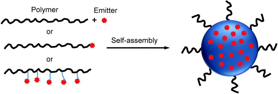 | ||
| Scheme 1 Schematic illustration of polymer-encapsulated organic nanoparticle preparation from self-assembly. | ||
2.2. Polymerization
In a typical polymerization method, the organic solvent containing monomers and organic emitters is uniformly dispersed into stable and small oil droplets in the presence of an emulsifier in aqueous solution through ultrasonification. The polymerization of monomers in oil droplets starts with the addition of initiators into the emulsion to yield organic nanoparticle dispersions (Scheme 2).49,50 Further solvent evaporation affords the well-dispersed polymeric nanoparticles. In this method, the emitters can be either reactive or non-reactive to the monomers during polymerization.51,52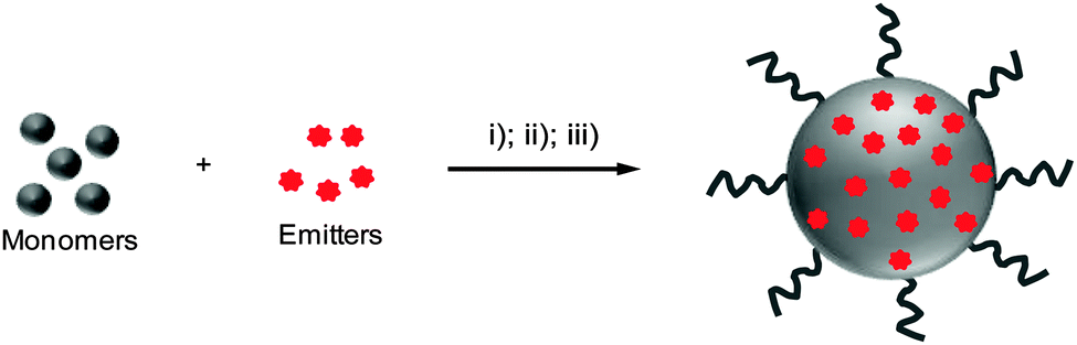 | ||
| Scheme 2 Schematic illustration of polymer-encapsulated organic nanoparticle preparation from in situ polymerization. (i) Addition of monomers and emitters in water containing an emulsifier; (ii) dispersion of monomers and emitters with sonication; (iii) addition of an initiator to initiate the monomer polymerization to yield emitter-loaded polymer nanoparticles. | ||
2.3. Emulsion
Emulsions can be generally classified into three types based on the sizes of the droplets, which are macroemulsion, miniemulsion and microemulsion.53 Miniemulsion and microemulsion are always employed to produce nanoparticles with sizes less than 500 nm, while the size of droplets in macroemulsion is larger than 1 μm.52 In a typical emulsion process, the emitters are dissolved in an organic solvent together with the polymer matrix to obtain a homogeneous solution. The organic solvent used in emulsion is immiscible with water (e.g., dichloromethane). When the solvent is added into emulsifier-containing aqueous solution under ultrasonification or vigorous stirring, small organic droplets are stabilized by the emulsifier to generate a homogeneous “oil-in-water” emulsion. After organic solvent evaporation, stable suspension of polymer encapsulated nanoparticles in water is obtained and the surface of these nanoparticles can be used for further functionalization (Scheme 3).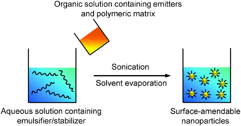 | ||
| Scheme 3 Schematic illustration of the preparation of polymer-encapsulated organic nanoparticles from emulsion. | ||
2.4. Nanoprecipitation
Nanoprecipitation differs from emulsion in the organic solvents used for nanoparticle formation. Nanoprecipitation requires the solvent to be miscible with water and there is no emulsifier present in the aqueous phase.54 In a typical nanoprecipitation process, the solution of emitters and the encapsulation matrix in an organic solvent (e.g., THF) is rapidly added to an excess of water under ultrasonification. The sudden decrease of solvent hydrophobicity leads to aggregation of emitters and hydrophobic segments of the encapsulation matrix to yield nanoparticles. The hydrophilic chains of the polymeric matrix orient into the aqueous phase to facilitate further functionalization (Scheme 4).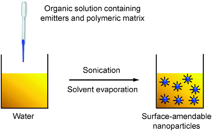 | ||
| Scheme 4 Schematic illustration of the preparation of polymer-encapsulated organic nanoparticles from nanoprecipitation. | ||
3. Fluorescence imaging
3.1. Polymer encapsulated conjugated polymer nanoparticles
For fluorescence imaging, brightness is highly desirable for good sensitivity at a low dosage of the contrast agent with reduced side effects. One main obstacle to obtain highly emissive CP nanoparticles is that neutral CPs often have reduced fluorescence when aggregated.55,56 Different strategies have been developed to overcome the intrinsic quenching effect of CPs in aggregates, such as through CP design, matrix selection and nanoparticle preparation. So far, CP nanoparticles with tunable size, brightness and surface properties have been customized to meet versatile requirements in in vitro and in vivo studies.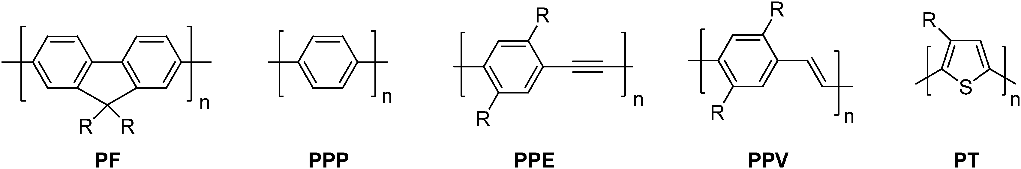 | ||
| Fig. 1 Chemical structures of PF, PPP, PPE, PPV and PT. | ||
It has been generally observed that CPs with short wavelength emission show higher fluorescence quantum yields than those with longer emission in both solution and solid state. This potentially poses new challenges as the increasing interest in in vivo fluorescence imaging studies requires advanced probes with FR/NIR emission, due to minimized photodamage to biological substrates, low background auto-fluorescence and deep tissue penetration in this wavelength range.63 Despite the large amount of CPs developed, bright FR/NIR fluorescent CPs remain very rare.64 Introducing donor–acceptor structures into CP backbones65 is the most widely used strategy to realize FR/NIR emission. These CPs suffer from significantly reduced fluorescence quantum yields in aqueous media, due to severe aggregation and charge transfer induced fluorescence quenching.66 Several strategies have been reported to optimize the FR/NIR CPs. For instance, a small amount of narrow-band-gap moieties as energy acceptors can be introduced into the CP backbones to facilitate intra- and interchain energy transfer in the aggregated state, which ensures both high absorptivity from the donor part and bright fluorescence from the acceptor units. Additionally, bulky pendants, such as POSS, can be incorporated into the FR/NIR CP backbone or side chain to effectively prevent close packing of the CPs to block energy transfer to low energy defects.60 Considering the fact that CPs are excellent light absorbers, they are ideal energy donors that could be used to blend with NIR emitters (e.g. organic dyes, QDs or acceptor CPs)67,68 for amplified NIR fluorescence in nanoparticles.
| CPs | Matrix | Sizea (nm) | λ ex (nm) | λ em (nm) | QY (%) | Colloidal stability | Targeting ligands | Application |
|---|---|---|---|---|---|---|---|---|
| a The sizes of nanoparticles were determined by dynamic light scattering (DLS) unless otherwise specified. b The sizes of nanoparticles were determined by TEM. c The size remains the same upon incubation in PBS buffer at 37 °C for 7 days. d No precipitation observed upon storing at 4 °C for 3 months. e The size increased from ∼15 nm to >2000 nm in the presence of 1 mM Cu2+ in water. f The size remains stable for months at 4 °C. g No obvious size variation observed in 10 days. | ||||||||
| CP1 | PLGA/PLGA-PEG-NH2 | ∼250 | 411 | 479 | 19 | — | Trastuzumab | In vitro targeted cell imaging77 |
| CP2 | DSPE-PEG-maleimide | 28 | 528 | 686 | 14 | — | Affibody | In vitro targeted cell imaging60 |
| CP3 | PLGA-COOH | 235 | 434 | 481 | 11 | — | Affibody | In vitro targeted cell imaging in a mixture (single laser excitation)81 |
| CP4 | 193 | 436 | 622 | 19 | — | RGD | ||
| CP5 | PLGA/PLGA-PEG-folate | 180 | 516 | 636 | 7 | — | Folate | In vivo dual-modality tumor imaging (fluorescence, MRI)86 |
| CP6 | DSPE-PEG-biotin | 55 | 460 | 545 | 18 | — | Biotin | In vitro targeted cell imaging44 |
| CP7 | DSPE-PEG DSPE-PEG-folate | 80 | 550 | 698 | 27 | Folate | In vitro/in vivo targeted cell/tumor imaging94 | |
| CP8 | DSPE-PEG | 36 | 461 | 582 | 32 | Tat peptide | In vitro long-term cell tracing95 | |
| CP9/IR775 | DSPE-PEG | — | No | In vivo RON imaging96 | ||||
| CP6 | PSMA | 15 | — | — | 28 | No | In vitro bioorthogonal labeling of cellular targets97 | |
| CP10 | 10 | — | 580 | 60 | — | Streptavidin | Intracellular microtubule targeting99 | |
| CP11 | PS-PEG-COOH | 16 | — | 540 | 18 | — | Streptavidin | In vitro photoswitching imaging111 |
| CP6/CP12 | — | 650 | 55 | — | Chlorotoxin | In vivo brain tumor targeting;112in vitro tracking of IGF1R113 | ||
| CP4/NIR775/Luc8 | 40 | — | 778 | — | — | RGD | Bioluminescence resonance energy transfer for in vivo tumor targeted imaging116 | |
| CP6 | PS-PEG-COOH/PIMA | 7 | 460 | 540 | 75 | Streptavidin | Protein location and orientation72 | |
| CP6 (C6 side chain) | F127/silica | 12b | 460 | 545 | 70–75 | No | In vivo brain vascular imaging119 | |
3.1.2.1. Poly(DL-lactide-co-glycolide) nanoparticles. As a Food and Drug Administration approved polymer, biocompatible poly(DL-lactide-co-glycolide) (PLGA copolymer) has been actively used as a carrier for drug delivery.73–75 PLGA-encapsulated CP nanoparticles with sizes of 240–270 nm and ∼190 nm could be synthesized through microemulsion and nanoprecipitation methods, respectively. The terminal carboxyl groups of PLGA allow further conjugation of functional moieties before or after nanoparticle formulation. Liu and co-workers developed a general strategy through a single emulsion method to fabricate a series of CP-loaded PLGA nanoparticles with emission covering the range from 400 to 700 nm.70 Although the CP nanoparticles were effective in targeted cellular imaging, the quantum yields of the as-prepared CP nanoparticles were 4–25 fold lower than those of CPs in tetrahydrofuran (THF) solutions, due to extensive CP aggregation in nanoparticles which promotes non-radiative decay.76 To reduce the close-packing of CP molecules upon nanoparticle formation, attaching POSS as an end-capper to poly(fluorenevinylene) led to CP1, and the CP1-loaded PLGA nanoparticles showed an improved quantum yield of 19% relative to 11% for poly(fluorenevinylene).77 The surface carboxyl groups of PLGA nanoparticles allowed further conjugation with trastuzumab through 1-ethyl-3-(3-dimethylaminopropyl)carbodiimide (EDC)-mediated coupling reaction. The trastuzumab-functionalized CP1-loaded nanoparticles were then successfully used for specific discrimination of SK-BR-3 cells from MCF-7 and NIH/3T3 cells. In addition to end chain modification, POSS has also been incorporated into the side chains of a polyfluorene derivative containing the narrow-band-gap moiety, 4,7-di(thiophen-2-yl)-2,1,3-benzothiadiazole (DBT), to yield CP2 with bright FR/NIR emission in aggregates.60CP2-based nanoparticles have a fluorescence quantum yield of 13.6% in water, which is ∼7-fold higher than that of the nanoparticles prepared using the counterpart without POSS attachment. Further surface immobilization with thiol-containing anti-HER2 affibody facilitated in vitro targeted imaging of HER2-overexpressed SK-BR-3 breast cancer cells. It is noteworthy that the higher quantum yield of CP2 nanoparticles ensures dramatically improved fluorescence contrast during confocal imaging (Fig. 2).
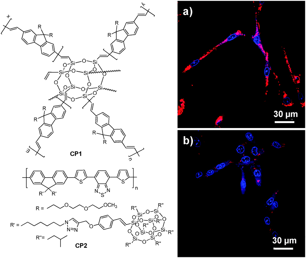 | ||
| Fig. 2 Chemical structures of CP1 and CP2. Confocal images of fixed SK-BR-3 breast cancer cells incubated with (a) affibody-functionalized CP2 nanoparticles and (b) affibody-functionalized nanoparticles prepared from the counterpart of CP2 without POSS. The images were taken under the same experimental conditions (reprinted with permission from ref. 60, Copyright 2013 Royal Society of Chemistry). | ||
By introducing a small portion of energy acceptors into CP backbones, efficient energy transfer from the donor to the acceptor could be triggered in the aggregate state,78–80 leading to amplified acceptor emission at the expense of the donor fluorescence. As such, CPs with energy donor–acceptor design are ideal to yield fluorescent nanoparticles with different emission colors upon single wavelength excitation at the same donor absorption maximum. CP3 is an analogue of CP1 with green fluorescence. Introducing a small portion of 2,1,3-benzothiadiazole (BT) units into the CP3 backbone led to CP4 with significantly red-shifted emission in aggregates because of aggregation enhanced energy transfer from the fluorenevinylene segments to the electron-deficient BT units.81 PLGA-encapsulated green and red nanoparticles with an average size of ∼190 nm and surface carboxyl groups were then synthesized through a single emulsion method. The obtained CP3 and CP4 nanoparticles have similar absorption maxima (434 nm and 436 nm) while their emission spectra are well-separated with maxima at 483 nm and 622 nm, respectively (Fig. 3a). The CP3 and CP4 nanoparticles were subsequently modified with anti-HER2 affibody and RGD peptide, which are specific targeting ligands to HER2 and integrin receptor, respectively. Owing to the specificity of targeting biomolecules and the distinct emission spectra, the well-separated fluorescence signals from affibody-CP3 and RGD-CP4 nanoparticles at the surface of SK-BR-3 cells and HT-29 cells allow simultaneous differentiation of the two cancer cell lines in a living cell mixture (Fig. 3b). As compared to single target detection, simultaneous identification of multiplex targets under single laser excitation has several advantages such as minimum instrument requirement, short testing time, reduced sample consumption and low overall cost.82
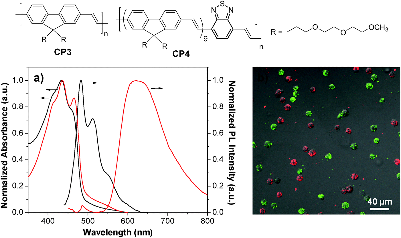 | ||
| Fig. 3 Chemical structures of CP3 and CP4. (a) UV-Vis and PL spectra of CP3 (black) and CP4 (red) nanoparticles. (b) Confocal images of a mixture of suspended living SK-BR-3 cells (green) and HT-29 cells (red) stained with affibody-CP3 and RGD-CP4 nanoparticles at 4 °C (λex = 405 nm) (reprinted with permission from ref. 81, Copyright 2011 American Chemical Society). | ||
As compared to CP nanoparticles with single modality, dual-modality nanoparticles offer great potential to satisfy the increasing requirements in advanced bioimaging applications through detection in both modes.83 In this regard, Green and co-workers reported the fabrication of fluorescent-magnetic nanoparticles through co-encapsulation of CPs and iron oxides (IOs) for cell imaging.84 The magnetic property was well preserved and the nanoparticles could be internalized by living SH-SY5Y cells for fluorescence imaging. However, the fluorescence of CPs was significantly sacrificed due to the quenching of CP fluorescence by IOs.85 To solve this problem, Liu and co-workers developed a facile strategy to synthesize similar nanoparticles with minimized fluorescence quenching by co-encapsulation of CP5 and lipid-coated IOs into a mixture of PLGA and PLGA-PEG-folate through a solvent extraction emulsion method (Fig. 4a).86 The yielded nanoparticles show super-paramagnetic properties with a saturated magnetization value of 3.42 emu g−1 without sacrificing the fluorescence, due to the lipid coating on iron oxides that acts as an effective barrier to minimize interaction between CP5 and IOs. The resulted dual-modality nanoparticles have an average size of ∼180 nm and are able to be readily internalized by MCF-7 cells without obvious cytotoxicity. The emission maximum locates at 636 nm with a large Stokes shift of 120 nm, which favors in vivo fluorescence imaging with high contrast (Fig. 4b).87 Additionally, a T2-weighted magnetic resonance (MR) signal is observed at the tumor site, which is in good accordance with the fluorescence imaging study (Fig. 4c). The prominent tumor uptake of nanoparticles could be attributed to the combined passive targeting and folate receptor-mediated active targeting effect. Later, the same group reported the application of ∼5 nm Au dots and CP5 co-loaded nanoparticles for fluorescence and dark field dual-modal in vitro targeted cancer cell imaging.88 TEM results showed that Au dots were eccentrically located at one side of the nanoparticles due to evaporation-induced phase separation between Au dots and the polymer matrix,89 which minimized the fluorescence quenching of CPs by Au dots. As a result, CPs have great potential in the construction of multi-modality nanoprobes for versatile in vitro and in vivo applications.
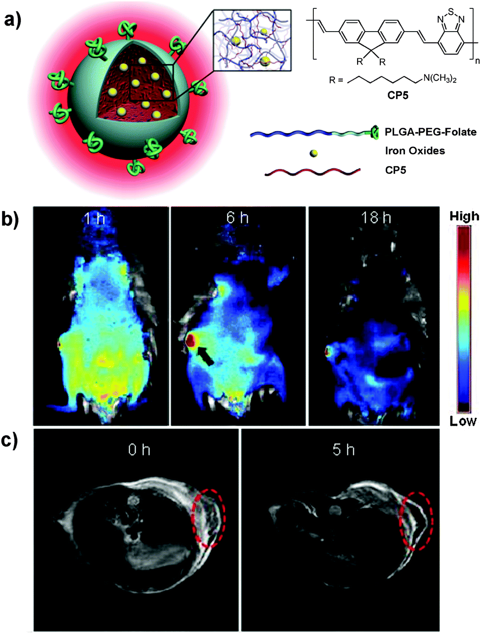 | ||
| Fig. 4 Chemical structure of CP5. (a) Schematic illustration of CP5-based dual-modality nanoparticles with surface folate groups. (b) Representative in vivo fluorescence images of the mouse injected with CP5 nanoparticles acquired at 1 h, 6 h and 18 h post-injection. (c) MR images of the mouse treated with CP5 nanoparticles at 0 and 5 h post-injection. Red circles in (c) indicate the tumor region (reprinted with permission from ref. 86, Copyright 2012 Wiley-VCH). | ||
Based on the several examples discussed above, it is obvious that the CP nanoparticles with the PLGA matrix often have sizes around 200 nm with medium to low fluorescence quantum yields. The high loading capacity of PLGA nanoparticles is ideal for co-encapsulation of several imaging or therapeutic agents with CPs to yield multimodality probes for imaging and therapy.86,90 However, PLGA based nanoparticles suffer from obvious shortcomings, e.g. the long-term colloidal stability is not ideal due to their large size and fast biodegradability. The excess of carboxyl groups on the nanoparticle surface also makes them vulnerable to aggregation in the presence of divalent metal ions.
3.1.2.2. DSPE-PEG nanoparticles. As amphiphilic macromolecules with favorable biocompatibility, DSPE-PEG derivatives are ideal matrices to encapsulate hydrophobic components to yield nanoparticles with small size (<100 nm) and excellent colloidal stability due to the presence of surface PEG. In addition, the utilization of different DSPE-PEG derivatives can afford nanoparticles with surface targeting ligands or functional groups with tunable densities for post-functionalization.91,92 Christensen and co-workers prepared a series of DSPE-PEG-encapsulated CP nanoparticles with average sizes of 55–83 nm in water, determined by DLS.44 Using CP6 as an example, DSPE-PEG encapsulated fluorescent nanoparticles with tunable surface groups (e.g., carboxyl group, biotin) showed similar sizes (∼55–58 nm) and quantum yields (∼17–19%). In addition, biotin–CP6 nanoparticles were able to specifically image surface receptor CD16/32 of J774A cells using biotinylated anti-CD 16/32 monoclonal antibody as a primary binding element and streptavidin as a linker in a sandwich format (Fig. 5).
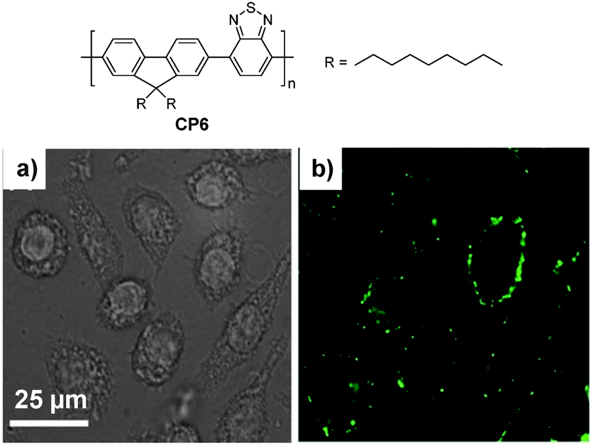 | ||
| Fig. 5 Chemical structure of CP6. Confocal (a) bright field and (b) fluorescence images of J774A cells labeled with biotinylated DSPE-PEG-encapsulated CP6 nanoparticles (reprinted with permission from ref. 44, Copyright 2011 Royal Society of Chemistry). | ||
To further develop bright CP nanoparticles with FR/NIR emission, a series of CPs were designed to contain narrow-band-gap energy acceptors in CP backbones. The design takes advantages of intra- and interchain energy transfer in nanoparticles with minimized fluorescence quenching due to acceptor dilution.93 A successful example is CP7, which contains two narrow bandgap moieties at a ratio of 80 (donor) to 20 (acceptor) in the backbone.94 When the donor segment was excited at 457 or 488 nm, efficient energy transfer occurred to facilitate FR/NIR emission. Using the mixture of DSPE-PEG and DSPE-PEG-folate as the matrix, the obtained folate–CP7 nanoparticles have an average size of ∼77 nm in water while the excitation and emission peaks are located at 465 nm and 698 nm, respectively. The fluorescence quantum yield of CP7 nanoparticles is ∼27% in water, which is among the highest for single component CP nanoparticles with FR/NIR emission. In vitro and in vivo studies reveal that the folate-functionalized nanoparticles have good targeting ability for folate receptor-overexpressed cancer cells and tumor tissues with low cytotoxicity and good biocompatibility. Obvious fluorescence signals were also observed in tumor, liver and spleen tissues at 24 h post-injection. Fig. 6 shows the semiquantitative biodistribution analysis, which suggests that the ratio of average fluorescence in the tumor tissue to that in the liver is 1.7 for folate–CP7 nanoparticle-treated mice. In addition, the fluorescence from the tumor in mice treated with folate–CP7 is ∼1.9-fold brighter than that for CP7 nanoparticle-treated ones, indicating the obvious targeting effect due to folate functionalization. Further in vivo experiments using tumor-free or H22 tumor-bearing ICR mice revealed that the folate–CP7 nanoparticles have no obvious in vivo toxicity. These results clearly indicate that CP nanoparticles can serve as an effective FR/NIR fluorescent probe for targeted in vivo fluorescence imaging and cancer diagnosis.
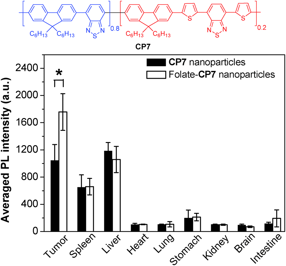 | ||
| Fig. 6 Chemical structure of CP7 and semiquantitative biodistribution analysis of folate-CP7 nanoparticles and CP7 nanoparticles in H22 tumor-bearing mice at 24 h post-injection (reprinted with permission from ref. 94, Copyright 2013 Wiley-VCH). | ||
Besides chemical modification of CPs, fine-tuning the size and morphologies of CP molecules in nanoparticles is another effective strategy to optimize their brightness and fluorescence quantum yields.95 Using DSPE-PEG as the encapsulation matrix, the initial feed concentration of CP8 in THF has a significant impact on the internal morphologies of CP molecules although the average sizes of the obtained nanoparticles are similar (∼36 nm). For instance, the higher initial CP8 concentration at 1.00 mg mL−1 led to nanoparticles with a typical core–shell structure and a fluorescence quantum yield of 17% (Fig. 7a). As the initial CP concentration decreased, the core–shell structure was transformed into dark dot embedded nanoparticles. At the initial CP8 concentration of 0.25 mg mL−1, single-chain CP dot (∼2–3 nm) embedded nanoparticles were obtained with a fluorescence quantum yield of 32%. This is due to the reduced non-radiative recombination from inter- and/or intra-chain interactions in the single-chain morphology, as evidenced by the lifetime results. The CP8 nanoparticles showed similar sizes (∼30 nm by DLS) in water when fabricated using either DSPE-PEG-COOH, DSPE-PEG-NH2 or DSPE-PEG-maleimide as the encapsulation matrix. Further conjugation with a cell penetrating trans-activator of transcription (Tat) peptide, Tat (RKKRRQRRRC), was achieved via carbodiimide-mediated coupling reaction for carboxyl- and amine-terminated nanoparticles or through click reaction between maleimide-terminated nanoparticles and thiol-labeled Tat. All three groups of Tat-functionalized nanoparticles showed better long-term cell tracing ability than the commercial Qtracker® 585 labeling kit. The Tat–CP8 nanoparticles prepared using the DSPE-PEG-maleimide matrix have the highest cell internalization efficiency (99.97%) and the best cell tracing performance of up to nine generations as confirmed by confocal microscopy (Fig. 7b and c).
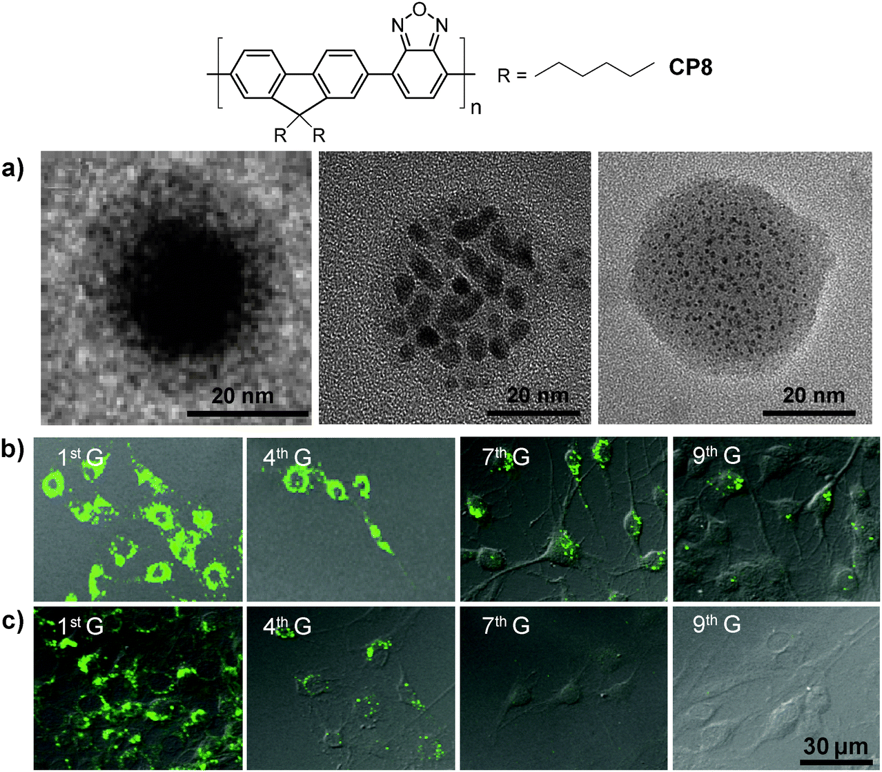 | ||
| Fig. 7 Chemical structure of CP8 and (a) TEM images of the nanoparticles prepared from different concentrations of CP8 in the feed: 1.00, 0.50 and 0.25 mg mL−1 (from left to right) using DSPE-PEG as the matrix. Confocal images of MCF-7 cancer cells labeled with 2 nM (b) Tat–CP8 nanoparticles prepared using the DSPE-PEG-maleimide matrix or (c) Qtracker® 585, after subculturing for different generations (G). All images in (b) and (c) share the same scale bar of 30 μm (reprinted with permission from ref. 95, Copyright 2013 Wiley-VCH). | ||
In addition to cellular imaging, Rao and co-workers reported the synthesis of CP based dual color nanoparticles for in vivo imaging of reactive oxygen and nitrogen species (RONs) in inflammatory microenvironments in living mice.96CP9 was first encapsulated in DSPE-PEG and DSPE-PEG-NH2 to yield NIR emissive nanoparticles with an emission maximum at 678 nm and a fluorescence quantum yield of 18%. The surface amine groups facilitated subsequent conjugation of carboxyl-terminated IR775 (IR775COOH) onto the nanoparticle surface (Fig. 8a). Upon excitation of CP9, the nanoparticles exhibited two emission peaks at 678 and 818 nm due to incomplete Förster resonance energy transfer (FRET) from CP9 to IR775, resulting in significantly reduced quantum yield from 18% to 3%. Upon gradual addition of RONs such as ONOO− to the nanoparticle solution, the emission peak at 678 nm increases with the concurrent loss of emission at 818 nm. This was due to the rapid oxidative cleavage of the oligomethine moiety of the IR775, which diminished FRET and recovered the donor fluorescence at 678 nm. Thereby, the FRET nanoparticle has a sensitive spectral change from a dual-peak profile to a single one upon RON activation. The performance of CP9/IR775 nanoparticles in in vitro RON imaging was carried out in the RAW264.7 cell line. As shown in Fig. 8b, only weak fluorescence from the cells was observed upon incubation with the nanoparticles. In contrast, cells pre-treated with bacterial cell wall lipopolysaccharide (LPS) and phorbol 12-myristate 13-acetate (PMA) that could elicit the production of RONs showed strong fluorescence, indicating the recovery of CP9 fluorescence activated by RONs under the same inflammatory condition. The cell fluorescence remains low in the presence of N-acetylcysteine (NAC), a general antioxidant that can effectively block the oxidative cleavage of IR775. The FRET nanoparticles also showed specific RON detection ability at inflammation sites in living bodies.
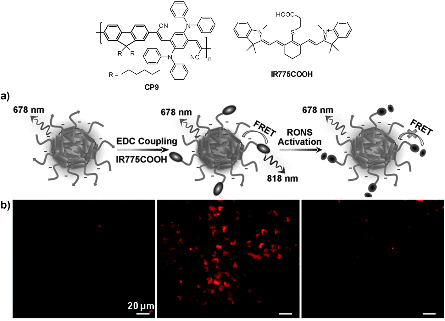 | ||
| Fig. 8 Chemical structures of CP9 and IR775COOH. (a) Schematic illustration of RON detection using CP9/IR775 FRET nanoparticles. (b) Fluorescence images of live murine macrophages (RAW 264.7) incubated with CP9/IR775 nanoparticles. From left to right: untreated cells, cells successively treated with LPS and PMA, and cells pre-treated with NAC before incubation with LPS and PMA, followed by NAC treatment. All the images share the same scale bar of 20 μm (reprinted with permission from ref. 96, Copyright 2013 Wiley-VCH). | ||
As discussed above, the nanoparticles made from DSPE-PEG have sizes in the range of 30–90 nm, which are smaller than those with PLGA because of the higher amphiphilicity and lower molecular weight of DSPE-PEG. As shown in Table 1, DSPE-PEG encapsulated CP nanoparticles also show good colloidal stability in aqueous media. More importantly, the versatile surface functional groups (e.g., carboxyl, amine, maleimide, biotin) of DSPE-PEG derivatives provide more opportunities for further surface functionalization. The surface PEG segments are also able to prolong the circulation time of DSPE-PEG nanoparticles in blood, which is highly desired in living animal studies.97 As a consequence, the DSPE-PEG encapsulated CP nanoparticles have been involved in a wide range of imaging applications, including in vitro/in vivo targeted imaging, long-term cell tracing and in vivo detection of reactive oxygen and nitrogen species, as summarized in Table 1.
3.1.2.3. Polystyrene block copolymer nanoparticles. Polystyrene (PS) based block copolymers were primarily used in Chiu's group to produce CP dots with very small sizes (<20 nm) for cellular imaging applications.31 They recently reviewed CP dots with fine-tuned surface properties for specific in vitro and in vivo targeted imaging and sensing of intracellular species (e.g., oxygen, pH and temperature).31 In this section, only the latest progress is summarized while specific examples are selected to highlight the impact of polymer matrix selection on nanoparticle fluorescence.
Considering the ultra-hydrophobicity of PS backbones, PS-containing amphiphilic block copolymers are promising choices to encapsulate CPs to form compact cores with very small sizes (7–15 nm). In 2011, Chiu's group reported the synthesis of CP6 based nanoparticles in the presence of poly(styrene-co-maleic anhydride) (PSMA).98 The obtained nanoparticles have an average diameter of ∼15 nm in water with abundant surface carboxyl groups to facilitate further functionalization. Of particular significance is that the small size of as-prepared nanoparticles is highly desirable for subcellular imaging, which is able to avoid the problems encountered by large-sized particles, such as poor mass transfer and non-specific adsorption. The same group further explored the application of streptavidin-tagged CP10 based nanoparticles (∼12 nm in water) for imaging microtubules in HeLa cells.99 The streptavidin on the nanoparticle surface allowed them to specifically bind to subcellular microtubules in the presence of biotinylated monoclonal anti-α-tubulin antibody (Fig. 9).
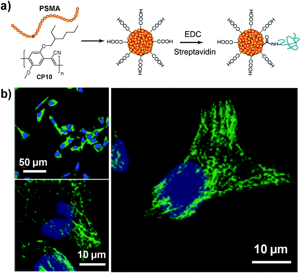 | ||
| Fig. 9 Chemical structure of CP10. (a) Surface functionalization of CP10 based nanoparticles and subsequent streptavidin bioconjugation via EDC-mediated coupling reaction. (b) Confocal images of microtubules in HeLa cells labeled with streptavidin-functionalized CP10 nanoparticles (reprinted with permission from ref. 99, Copyright 2012 Royal Society of Chemistry). | ||
The same group subsequently reported that by using PS-PEG-COOH as the polymer matrix it was possible to obtain CP6 nanoparticles with excellent colloidal stability.71 Further addition of a dodecylamine-grafted poly(isobutylenealt-maleic anhydride) (PIMA) as the co-encapsulation matrix and the use of a low concentration of CP6 in the feed yielded very small nanoparticles (7 nm in diameter) with up to 75% fluorescence quantum yield in water.72 Careful investigation of the huge improvement in quantum yield revealed that the low mass ratio of CP6 to the encapsulation matrix (1![[thin space (1/6-em)]](https://www.rsc.org/images/entities/char_2009.gif) :45) played an essential role. On average, each nanoparticle contains one CP6 chain, which significantly minimizes the fluorescence quenching through CP molecule aggregation.100 Single particle imaging results suggested that the brightness of individual nanoparticles was nearly identical to that of Qdot 525 upon excitation at 488 nm. Further conjugation of the CP6 nanoparticles with streptavidin facilitated their application in monitoring both protein location and the changes in protein orientation upon excitation with a polarized light.
:45) played an essential role. On average, each nanoparticle contains one CP6 chain, which significantly minimizes the fluorescence quenching through CP molecule aggregation.100 Single particle imaging results suggested that the brightness of individual nanoparticles was nearly identical to that of Qdot 525 upon excitation at 488 nm. Further conjugation of the CP6 nanoparticles with streptavidin facilitated their application in monitoring both protein location and the changes in protein orientation upon excitation with a polarized light.
On the other hand, the large extinction coefficient and highly delocalized backbone structure make CPs excellent candidates as energy donors to construct fluorescent probes based on FRET.101 By incorporating energy acceptors with versatile optical properties into CPs through either a non-covalent or covalent approach, nanoparticles with photoswitchable fluorescence, NIR emission and amplified acceptor signals have been developed for oxygen sensing, intracellular pH/temperature sensing, etc.102–105 Taking fluorescence photoswitching probes as an example, they have become increasingly important in super resolution imaging, in vivo protein concentration determination and protein trafficking in living cells.106–108 The photoswitchable probes have been realized through co-loading CP and a photochromic molecule (e.g., diarylethene) into polymer matrices.109,110 In addition, covalent attachment of spiropyran to the side chain of a copolymer led to CP11, which upon encapsulation with PS-PEG-COOH yielded CP11 nanoparticles with an average size of ∼16 nm by DLS (Fig. 10).111 The repeatable modulation of fluorescence was achieved by UV irradiation that could convert spiropyran into its visible-absorbing merocyanine form, which can efficiently quench the fluorescence of CP11via FRET. On the other hand, exposure under visible light recovered the spiropyran, which resulted in fluorescence regeneration. As compared to co-loaded CP/photochromic molecule nanoparticles,109,110 the molar ratio of CP to photochromic molecule is well-controlled in CP11, so that batch-to-batch variation in nanoparticles generated from the non-covalent blending approach can be avoided.
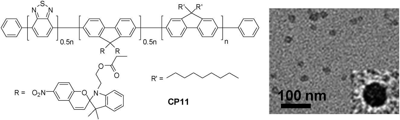 | ||
| Fig. 10 Chemical structure of CP11 and the TEM image of CP11 nanoparticles using PS-PEG-COOH as the encapsulation matrix (reprinted with permission from ref. 111, Copyright 2012 American Chemical Society). | ||
Energy donor–acceptor based nanoparticles have also been prepared by simultaneous encapsulation of two different CPs into the same polymer matrix to result in large absorption cross-sections in the visible range and high quantum yields in FR/NIR emission.112 Howarth and co-workers reported that CP6/CP12 hybrid nanoparticles can be prepared through encapsulation with PS-PEG-OH or PS-PEG-COOH, which led to hydroxy- and carboxy-CP6/CP12 nanoparticles with the same emission maximum at 635 nm. The nanoparticles with the PS-PEG-OH matrix showed dramatically reduced non-specific cell binding as compared to those based on the PS-PEG-COOH matrix.113 For example, nonspecific binding of carboxy-CP6/CP12 nanoparticles to mammalian cells and glass coverslips was obvious in the presence of 100 nM Ca2+ in the extracellular medium. In contrast, only minimal nonspecific binding of hydroxy-CP6/CP12 nanoparticles to cells and coverslips was observed (Fig. 11). Owing to the low nonspecific binding of the hydroxy-CP6/CP12–streptavidin nanoparticles, they have been successfully used to track the dynamics of Type I insulin-like growth factor receptor (IGF1R) on breast cancer cells.
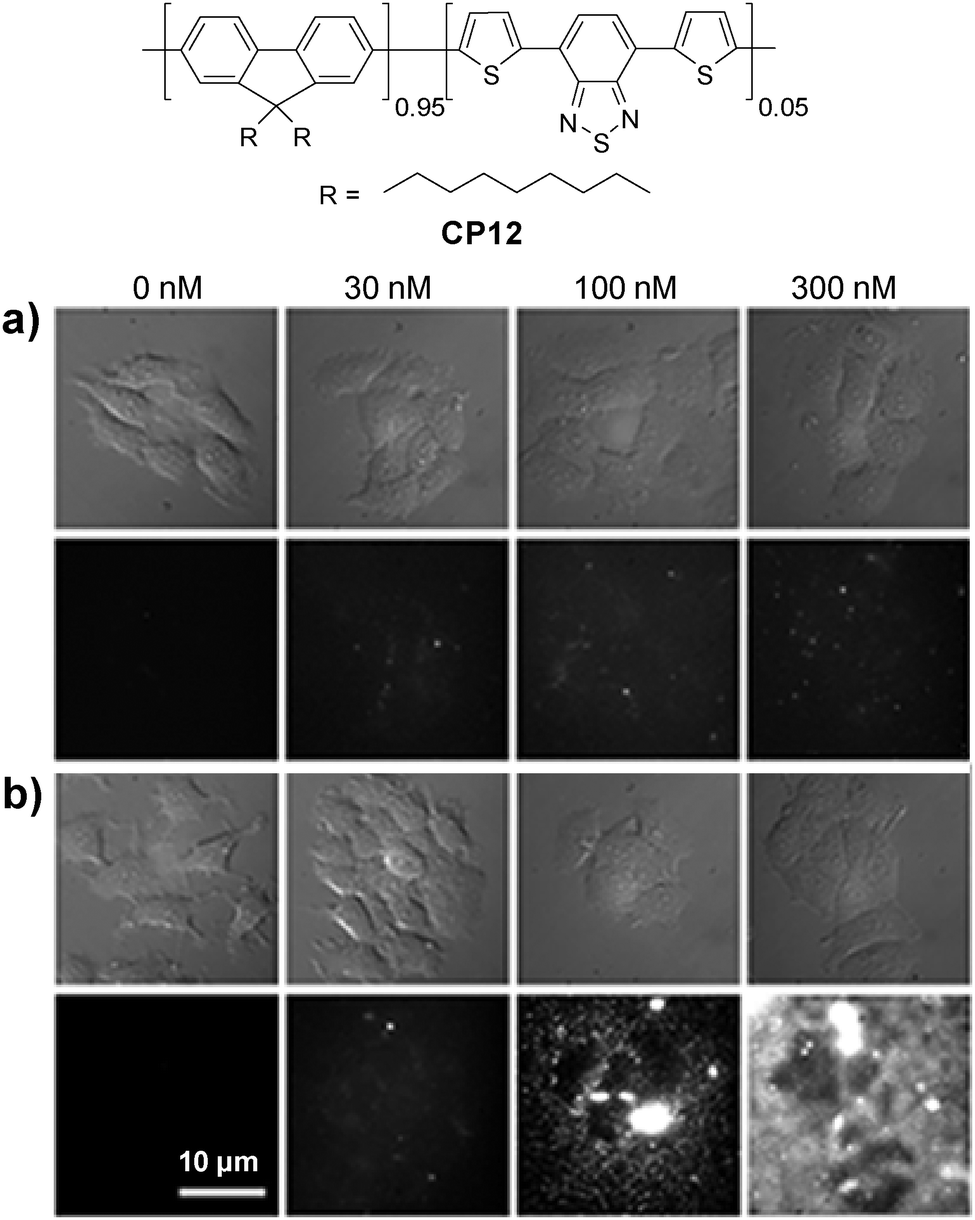 | ||
| Fig. 11 Chemical structure of CP12. Bright-field and fluorescence images of MCF-7 cancer cells incubated with different concentrations of (a) hydroxyl-CP6/CP12 nanoparticles and (b) carboxy-CP6/CP12 nanoparticles for 10 min in the presence of different concentrations of Ca2+ in extracellular media. All images share the same scale bar of 10 μm (reprinted with permission from ref. 113, Copyright 2013 American Chemical Society). | ||
For fluorescence imaging, the light penetration often limits the imaging depth, due to the absorption and scattering of optical photons in tissues.114 To address this challenge, the concept of self-luminescing hybrid probes based on the principle of bioluminescence resonance energy transfer (BRET) from a bioluminescent protein to QDs offers new research opportunities.115 Rao and co-workers designed self-luminescing NIR nanoparticles by integrating BRET and FRET in an energy transfer relay.116 The self-luminescing NIR nanoparticles were prepared by nanoprecipitation using CP13 and NIR775 as the emitters and PS-PEG-COOH as the matrix, followed by conjugation with a bioluminescent eight-mutation variant of R. reniformis luciferase (Luc8) and RGD peptide (Fig. 12). Three emission peaks from Luc8, CP13 and NIR775 are located at 480, 594 and 778 nm, respectively, indicating efficient BRET from Luc8 to CP13, followed by FRET from CP13 to NIR775. Upon intravenous administration of the nanoparticles into mice, strong NIR fluorescence signals were observed from the lymphatic networks, including neck lymph nodes, axillary lymph nodes, inguinal lymph nodes and lateral thoracic lymph nodes. Comparison between the bioluminescence imaging and fluorescence imaging (λex = 465 nm) was conducted by intravenous injection of the self-luminescing nanoparticles into mice bearing exnografted tumors. It was found that the signal ratio between the tumor and background from bioluminescence imaging was ∼10–50 fold higher than that from fluorescence imaging at each time point post-injection. The novel self-luminescing nanoparticles provided highly improved sensitivity through bioluminescence imaging in in vivo studies.
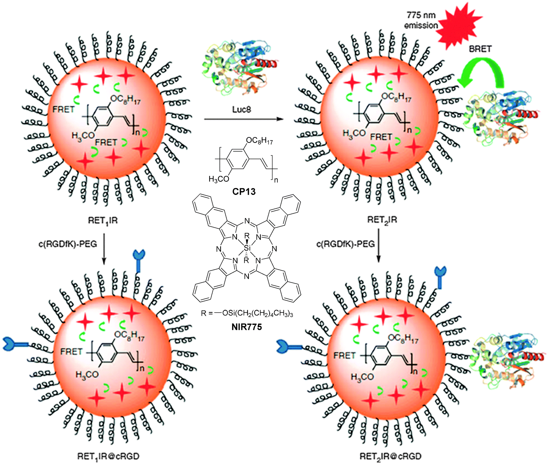 | ||
| Fig. 12 Chemical structures of CP13 and NIR775. Schematic illustration of self-luminescing BRET-FRET NIR polymeric nanoparticles (reprinted with permission from ref. 116, Copyright 2012 Nature Publishing Group). | ||
As compared to PLGA and DSPE-PEG derivatives, PS-containing copolymers are likely to form more compact hydrophobic cores during self-assembly due to the high hydrophobicity of PS. The compact hydrophobic cores are beneficial to reduce the contact of encapsulated CP molecules with water, leading to high fluorescence quantum yields. In addition, PS-containing block copolymers can afford very small size nanoparticles in water due to the low molecular weight and ultra-hydrophobic PS segments. The small sizes (∼15 nm) of PSMA/PS-PEG nanoparticles make them promising in intracellular microtubule labelling, in vitro membrane receptor tracking and in vivo brain tumor imaging. However, the PSMA-encapsulated nanoparticles suffer from poor colloidal stability in aqueous media that have either high ionic strength or bivalent metal ions, which can be improved using polyelectrolyte coating.117 It is important to note that the CP6 based PS-PEG-COOH nanoparticles show much higher brightness as compared to IgG-Alexa 488 and Qdot 565 in single particle imaging (Fig. 13a–c). Statistical analysis reveals that the CP6 nanoparticles exhibit an order-of magnitude improvement in the signal-to-background ratio (Fig. 13d and e). More importantly, the pronounced fluorescence intermittency of QDs, referred to as blinking, is absent in CP6 nanoparticles, but is obvious for Qdot 565 (Fig. 13f). Flow cytometry data suggest that the average brightness of CP6 nanoparticle-labeled cells is ∼25-fold and ∼18-fold higher than that of the cells labeled with Qdot 565-IgG and Alexa-IgG, respectively. In addition, the CP6 nanoparticles also show good colloidal stability, which can be kept for over 6 months. Indeed, CP6 is the most widely used CP for nanoparticle fabrication, which has been used for targeted cellular imaging,44 protein location detection72 and in vivo vascular imaging.118
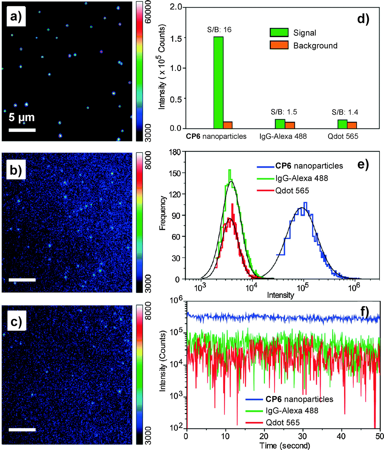 | ||
| Fig. 13 Single-particle fluorescence images of (a) CP6 nanoparticles, (b) IgG-Alexa 488, and (c) Qdot 565 obtained under identical conditions. (d) Signal and background ratios for a single CP6 nanoparticle, single IgG-Alexa 488 and single Qdot 565. (e) Intensity distributions of single-particle fluorescence for the three probes under an excitation power of 4 mW. (f) Single-particle photobleaching trajectories. Images in (a), (b) and (c) share the same scale bar of 5 μm (reprinted with permission from ref. 71, Copyright 2010 American Chemical Society). | ||
3.1.2.4. F127 nanoparticles. F127 is a biocompatible triblock copolymer composed of a central hydrophobic chain of poly(propylene oxide) (PPO) connected with two hydrophilic chains of PEG. Due to the long hydrophobic PPO segments and amphiphilic property, F127 can efficiently encapsulate hydrophobic agents with a compact core to efficiently prevent contact of CP molecules with oxygen and water to reduce the quenching effect.119 Liu and co-workers reported the synthesis of PFBT-loaded F127 micelles with a size of ∼10 nm in water. The PFBT used in this study is an analogue of CP6 with six carbons in the side chains. At a matrix to PFBT weight ratio of 200
:1, the quantum yield of the obtained F127 nanoparticles was 70%, which is much higher than that for PFBT-loaded DSPE-PEG nanoparticles (40%) prepared under the same conditions. As compared to DSPE-PEG, the more hydrophobic PPO segments in F127 molecules can entangle with PFBT backbones more efficiently to isolate CP molecules in the matrix, leading to reduced interchain interaction with fluorescence quantum yield enhancement.120 Further coating the F127 micelles with a silica layer resulted in nanoparticles with excellent photostability and an improved quantum yield of 75%. Single particle imaging studies (Fig. 14) suggest that on average, each silica-coated F127-PFBT nanoparticle (∼12 nm) emits a similar total number of photons as the DSPE-PEG-PFBT nanoparticle (∼30 nm). The silica-coated F127-PFBT nanoparticles also showed a large two-photon absorption action cross-section value of 814 GM at 810 nm based on CP chain concentrations. After intravenous injection of the nanoparticles, the major blood vessels and microvasculature deep in the brain that lies beyond the pia matter (500 μm) could be clearly visualized upon 800 nm excitation. In addition, no large aggregates were observed in the brain blood vessels, due to the surface protection of PEG segments. Although the fluorescence quantum yield of F127 encapsulated nanoparticles is very high, the brightness in each nanoparticle is limited by the total number of emitters encapsulated.
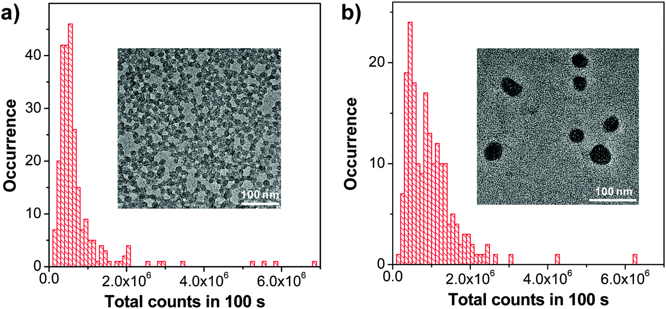 | ||
| Fig. 14 Histograms of the total number of photons collected for (a) silica-coated F127-PFBT nanoparticles and (b) DSPE-PEG-PFBT nanoparticles. λex = 488 nm. Insets show the TEM images of (a) and (b), respectively. | ||
3.2. AIE fluorogen based nanoparticles
As aggregation of organic emitters is a natural process during nanoparticle synthesis, fluorogens with AIE characteristics are ideal to construct highly fluorescent nanoparticles. The development of various AIE fluorogens, the restriction of intramolecular rotation (RIR) mechanism together with their potential applications have been discussed in detail in previous publications.121–123 This part only covers the recent progress in AIE nanoparticles, with a special focus on creating long wavelength emissive AIE nanoparticles for bioimaging applications. The general strategies to yield fluorogens with long wavelength emission are to increase their conjugation length or through introduction of donor–acceptor structures.124 These fluorogens often show low fluorescence in the solid state, due to strong π–π interactions.125 Tang et al. discovered that conjugation between a typical AIE unit (e.g. tetraphenylethylene (TPE)) and conventional ACQ molecules (AIE + ACQ) could effectively transform them into AIE fluorogens with red-shifted emission. For example, as shown in Fig. 15a, A1 was obtained through attachment of two TPE pendants to perylene-3,4:9,10-tetracarboxylic bisimide with ACQ characteristics.126A1 shows the typical AIE signature: the fluorescence of A1 in THF solution is very faint, but it steadily increases upon addition of water into THF due to the formation of aggregates. This simple molecular transformation strategy has also been successfully employed in the synthesis of FR/NIR AIE fluorogens through conjugation of TPE with other AIE units (AIE + AIE) or fluorogens with twisted intramolecular charge transfer (TITC) characteristics (AIE + TITC). As an example, fluorogen A2 was synthesized by attaching two TPE units to a well-known red emitter, 2-{2,6-bis[(E)-4-(diphenylamino)styryl]-4H-pyran-4-ylidene}malononitrile, which has both TITC and ACQ features.127A2 shows typical TITC and AIE properties, and the fluorescence of A2-loaded nanoparticles is almost linearly intensified as the amount of encapsulated A2 increases within the studied concentration range (Fig. 15b). The high brightness of AIE fluorogens in the solid state and the distinct feature that AIE fluorogens become stronger emitters at higher concentrations make them promising candidates for the development of organic nanoparticles. So far, several strategies, such as polymer conjugation, polymer matrix encapsulation and in situ polymerization, have been used to form AIE nanoparticles for in vitro and in vivo applications. The absorption and emission maxima, the sizes and quantum yields of the reported polymer encapsulated AIE nanoparticles together with their matrices and applications are summarized in Table 2.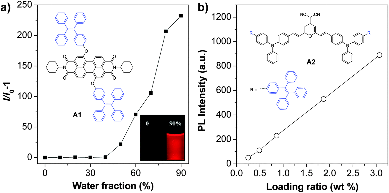 | ||
| Fig. 15 (a) A typical AIE phenomenon: plot of I/I0 − 1 as a function of water fraction in THF–water mixtures, where I and I0 are the fluorescence intensities of A1 in THF–water mixtures in the presence and absence of water, respectively (reprinted with permission from ref. 126, Copyright 2012 Royal Society of Chemistry). (b) Plot of the fluorescence intensity versus the weight ratio of A2 in BSA nanoparticles (reprinted with permission from ref. 127, Copyright 2012 Wiley-VCH). | ||
| AIE fluorogen | Matrix | Sizea (nm) | λ ex (nm) | λ em (nm) | QY (%) | Colloidal stability | Targeting ligands | Application |
|---|---|---|---|---|---|---|---|---|
| a The sizes of nanoparticles were determined by DLS unless otherwise specified. b The sizes of nanoparticles were determined by TEM. c A6-PLGA nanoparticles with eccentric loading of AIE fluorogens. d A6-PLGA nanoparticles with homogeneous loading of AIE fluorogens. e No obvious precipitation upon storage at 4 °C for 3 months. f Same size after incubation in PBS buffer at 37 °C for 10 days. g No obvious precipitation upon storage at 4 °C for months. h Stable size in PBS buffer and in water over a wide pH range of 4–10. | ||||||||
| A1 | DSPE-PEG-folate | 57 | 514 | 680 | 8 | — | Folate | In vitro targeted cell tracing126 |
| A2 | BSA | 148 | 505 | 668 | 12 | — | No | In vivo cell imaging127 |
| A3 | Chitosan | — | — | — | — | — | No | In vitro cell tracing128 |
| A4 | 200–400b | — | — | 25 | — | No | In vitro cell imaging129 | |
| A5 | DSPE-PEG derivatives | <30b | 435 | 577 | — | — | RGD peptide | In vivo SLN mapping and targeted tumor imaging20 |
| A6 | 30 | 511 | 671 | 24 | Tat peptide | In vitro/in vivo cell tracing132,134 | ||
| In vivo vascular imaging133 | ||||||||
| A7 | 33 | 423 | 539 | 58 | Tat peptide | |||
| A8 | 36 | 480 | 619 | 55 | NLS Tat peptide | In vitro cell tracing and nucleus imaging136 | ||
| A9 | 38 | 480 | 617 | 67 | NLS Tat peptide | |||
| A6/NIR 775 | 30b | — | — | 9 | — | No | In vivo imaging140 | |
| A10 | C18PMH-PEG | 70 | 475 | 650 | 14.9 | Folate | In vivo targeted tumor imaging142 | |
| A11 | PS-PMAA | 68 | 365 | 486 | 62.1 | — | No | In vitro cell imaging143 |
| A10 | — | 489 | 610 | 22.3 | — | No | ||
| A6 | PLGA/PLGA-PEG-folate | 202c | 515 | 670 | 30 | — | Folate | In vitro cell imaging141 |
| 177d | 515 | 670 | 17 | — | ||||
| A12 | In situ polymerization | 120 | — | 612 | — | — | No | In vitro cell imaging146–148,150 |
| A13 | 303 | 470 | 607 | — | — | No | ||
| A14 | 472 | — | 578 | — | — | No | ||
| A15 | 25 | 410 | 518 | 40 | — | No | ||
 | ||
| Fig. 16 Chemical structures of A3 and A4. Fluorescent images of HeLa cells stained by A3–chitosan conjugates at different passages (P) (reprinted with permission from ref. 128, Copyright 2013 American Chemical Society). | ||
As compared to many reported fluorescent dye–polymer conjugates, conjugation of AIE fluorogens to polymers yielded highly fluorescent polymers. It is also interesting to note that the polymer fluorescence will intensify with the increased amount of AIE fluorogens conjugated to the polymer. AIE fluorogens bearing aldehyde groups could be conjugated to natural polysaccharides, chitosan, etc., to afford self-assembled nanoparticles with good living cell internalization efficiency and excellent biocompatibility for long-term cell tracing.128 Further development of FR/NIR AIE fluorogens will likely yield highly fluorescent biocompatible polymers for practical applications. Despite a useful strategy, it requires specific modification of each AIE fluorogen prior to polymer conjugation and nanoparticle formation.
 | ||
| Fig. 17 Chemical structure of A5 and (a) TEM image of the A5 nanoparticles and (b) in vivo fluorescence image of mice bearing subcutaneous tumor xenografts upon injection of A5 nanoparticles (top) and RGD-A5 nanoparticles (bottom) (reprinted with permission from ref. 20, Copyright 2011 Elsevier B.V.). | ||
In 2013, Tang et al. reported the synthesis of an FR/NIR emissive AIE fluorogen via the AIE + AIE approach. A6 was obtained by conjugating TPE with an AIE active molecule of 2,3-bis[4-(diphenylamino)phenyl]fumaronitrile.132 Such conjugation not only maintained the AIE characteristics of the molecule, but also led to FR/NIR emission for A6. Encapsulation of A6 with a mixture of DSPE-PEG and DSPE-PEG-NH2 yielded A6-based nanoparticles with a uniform average size of ∼30 nm in water and a fluorescence quantum yield of 24%. Due to their small and uniform sizes, these AIE nanoparticles were also termed AIE dots. The dots showed absorption and emission maxima at 511 and 671 nm. Further functionalization of the dots with Tat (RKKRRQRRRC) peptide afforded Tat-AIE dots that are over 10-fold brighter than the commercial Qtracker® 655 in single nanoparticle imaging analysis. It is noteworthy that the notorious blinking behavior of QDs is absent in these Tat-AIE dots. In vitro and in vivo studies suggested that Tat-AIE dots were able to trace MCF-7 cells up to 12 passages and C6 cells up to 21 days. Upon subcutaneous injection in living mice, the fluorescence from cells treated with Tat–A6 dots remained very high at day 12 post-injection while that from cells treated with Qtracker® 655 vanished at day 7 (Fig. 18). The high quantum yield and FR/NIR emission of A6 dots ensured in vivo tracing of the labeled cells with high contrast. The A6 dots have also been reported to be an effective contrast agent for in vivo two photon fluorescence imaging.132,133
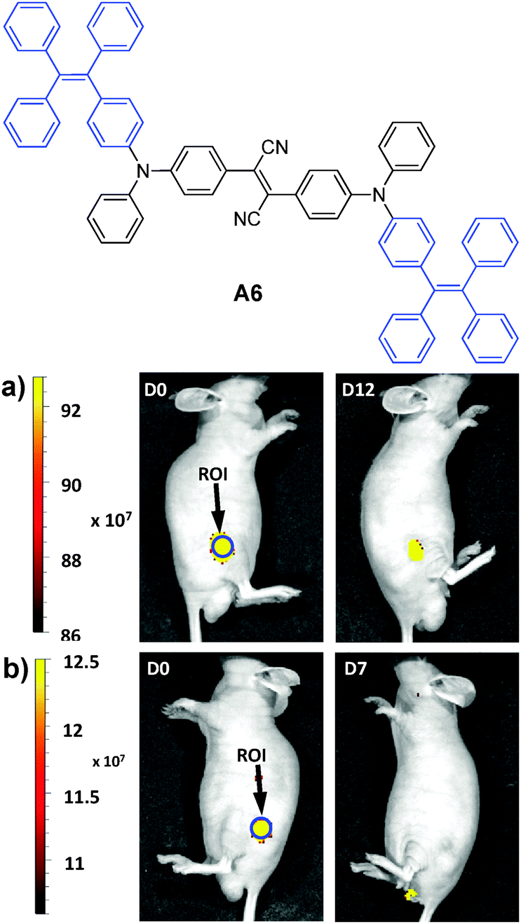 | ||
| Fig. 18 Representative in vivo fluorescence imaging of the mouse subcutaneously injected with 1 × 10⁶ of C6 glioma cells labeled with (a) Tat–A6 dots and (b) Qtracker® 655. The images were taken on designated days post cell injection. ROI: region of interest (reprinted with permission from ref. 132, Copyright 2013 Nature Publishing Group). | ||
The A6 dots together with their green fluorescent analogues have been further used to monitor the migration behaviors and interactions between two populations of cancer cells.134 The A6 and A7 AIE dots were prepared by nanoprecipitation using DSPE-PEG-maleimide as the polymer matrix, followed by surface functionalization with thiol-decorated Tat peptide through the thiol-maleimide coupling reaction. Both dots show large Stokes shifts and have an intense absorption intersection at 455 nm with a high extinction coefficient of ∼4 × 10⁷ M−1 cm−1. Due to their distinct emission peaks at 539 and 670 nm with minimal spectral overlap (Fig. 19), the Tat functionalized A6 and A7 dots were further employed to label and track the interaction between two groups of highly motile HT1080 cells. Ex vivo imaging of the lung tissues from the mouse injected with the mixture of cells separately labeled with these dots revealed no fluorescence signal interference. Dual-modality AIE dots with both fluorescent and magnetic properties were further obtained through surface attachment of diethylenetriaminepentaacetic (DTPA)–gadolinium(III) on A6 Tat-AIE dots, which allowed accurate analysis of the biodistribution of labeled cells through gadolinium(III) ion quantification.135 The excellent performance of these AIE dots makes it possible to monitor cell interaction and migration during metastasis using a mouse model.
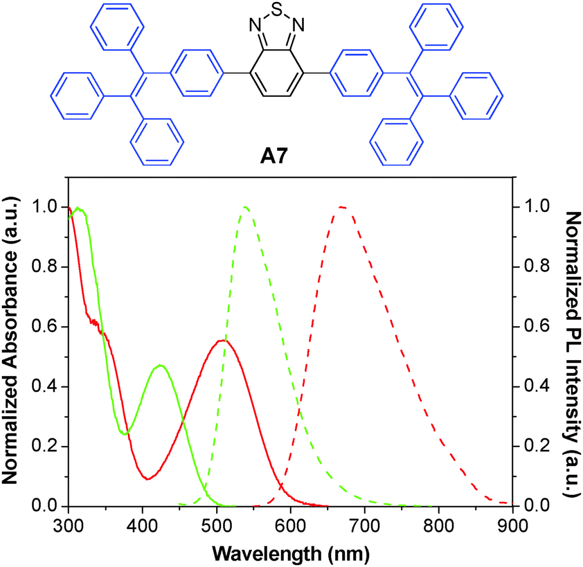 | ||
| Fig. 19 Chemical structure of A7. The absorption (solid line) and emission (dashed line) spectra of A6 (red) and A7 (green) dots in water (reprinted with permission from ref. 134, Copyright 2013 American Chemical Society). | ||
The versatile surface functionalities make DSPE-PEG encapsulated AIE dots suitable for diverse bioconjugation. Based on the TICT + AIE strategy, Tang and co-workers synthesized two new fluorogens (A8 and A9) that showed both TICT and AIE features (Fig. 20a).136 Conjugation of A8 and A9 AIE dots with a nuclear localization signal (NLS) Tat sequence (YGRKKRRQRRRC) yielded NLS Tat-AIE dots, which exhibited certain permeability to cellular nucleus (Fig. 20b). It is noteworthy that the A8 and A9 AIE dots have fluorescence quantum yields as high as 55% and 67% in water, respectively, ensuring high contrast in cell imaging. The ultrahigh brightness, good photostability and low cytotoxicity of these NLS Tat-AIE dots enable them to trace MCF-7 cancer cells up to 7 days.
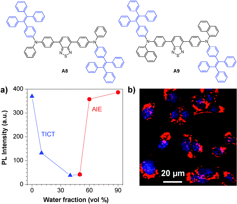 | ||
| Fig. 20 Chemical structures of A8 and A9. (a) Plot of PL intensity versus water fraction in the THF–water mixture of fluorogen A8. (b) Confocal images of C6 cells labeled with A8 NLS-AIE dots (reprinted with permission from ref. 136, Copyright 2013 Wiley-VCH). | ||
In addition to cell tracking, the bright AIE dots have also been used for in vivo two-photon fluorescence imaging of intravital blood vessels.137 The A7 dots have a small size of ∼33 nm with a high quantum yield of 62%, a large two photon absorption action cross section value of 6.3 × 10⁴ GM (810 nm) based on dot concentration, and low in vivo toxicity. Upon intravenous injection, the major blood vessels, the smaller capillaries in the pia matter as well as the microvasculature deep in the brain that lies beyond the pia mater were clearly visualized with imaging depth up to 500 μm and resolution up to a few micrometers (Fig. 21a). The vascular systems in skull bone marrow and skin were also imaged to demonstrate the in vivo two photon fluorescence imaging ability of AIE dots (Fig. 21b and c). Similar results have also been observed for DSPE-PEG encapsulated A6 dots,133 which indicate that AIE dots with good photostability provide a novel platform to visualize blood vessels in vivo for better understanding of biological processes, such as angiogenesis and vascular leakage. These studies also offered fundamental guidelines for future design of novel AIE probes with two-photon excited fluorescence imaging capability for potential clinical translation.
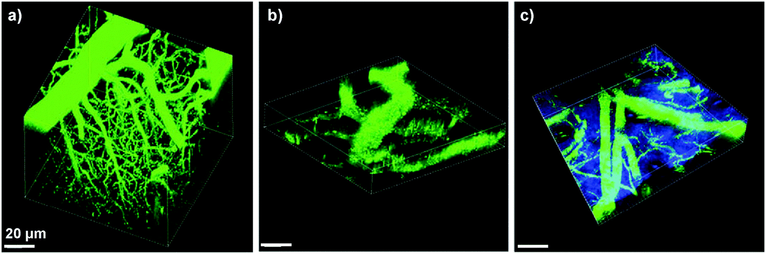 | ||
| Fig. 21 3D reconstructed two-photon fluorescence images of blood vessels in (a) brain (0–425 μm), (b) bone marrow (0–108 μm), and (c) mouse ear skin (0–132 μm) from the mouse injected with A7 AIE dots. All images share the same scale bar of 20 μm (reprinted with permission from ref. 137, Copyright 2013 Wiley-VCH). | ||
One of the intrinsic limitations of the currently available AIE dots is their broad emission spectra, which limit their application in multiplexing. This is due to the large conformational difference in the ground state and the first singlet excited state as well as the abundant vibration energy levels of the torsional molecule structures for AIE fluorogens.138 Due to the good spectral overlap between A6 emission and NIR775 absorption, co-encapsulation of A6 and NIR775 in DSPE-PEG yielded fluorescent nanoparticles with narrow NIR emission.139 With increasing NIR775 mass ratios from 0.5% to 1.5%, the A6 emission from 550 to 750 nm was greatly quenched while the NIR775 emission band from 750 to 900 nm increased gradually upon excitation of A6 at 510 nm. A further increase in the NIR775 concentration up to 4% resulted in reduced NIR emission intensity caused by self-quenching of NIR775. With 1.5% mass ratio in the feed, the emission intensity of NIR775 upon excitation at 510 nm was ∼47-fold higher than that upon direct excitation of NIR775 at 760 nm. Additionally, the A6/NIR775 nanoparticles showed a band width of only 20 nm with a fluorescence quantum yield of ∼7%. In vivo imaging study revealed that the intravenously injected A6/NIR775 nanoparticles were able to provide 5.2-fold higher fluorescence contrast in live animals upon excitation at 523 nm vs. 704 nm. As a result, the FRET strategy offers new opportunities to synthesize AIE dots with high brightness and narrow emission, simply by selecting suitable donor–acceptor pairs.
So far, most of the AIE nanoparticles were fabricated using DSPE-PEG as the matrix due to their simple process. These nanoparticles, especially those based on A6, generally have a much smaller size (30–50 nm) as compared to those obtained via AIE fluorogen–polymer conjugate self-assembly. Due to their small size and very good photo- and colloidal stability, these nanoparticles have been widely used for in vitro and in vivo cell tracing,126–129 targeted tumor imaging142 and in vivo SLN mapping (Table 2).24 Of significant interest is Tat functionalized and DSPE-PEG encapsulated A6 dots, which showed superior performance over commercial Qtracker® 655 in both in vitro and in vivo cancer cell tracing. As most FR/NIR AIE fluorogens contain donor–acceptor structures, the reported AIE dots are also two-photon active, enabling them to be used for two-photon fluorescence imaging with a higher penetration depth than the commonly used one-photon fluorescence imaging.133,137 The reported AIE/NIR dye co-encapsulation strategy successfully addressed the disadvantage of the broad emission spectra for AIE dots,139 which opens new opportunities for potential AIE dot based multiplexing.
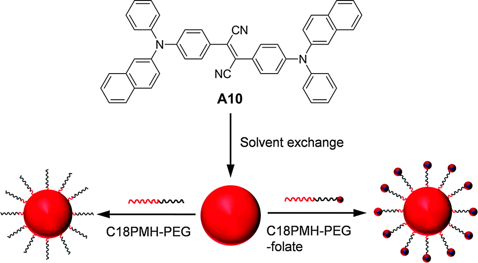 | ||
| Fig. 22 Chemical structure of A10 and schematic illustration of the synthesis of A10 nanoparticles coated with C18PMH-PEG and C18PMH-PEG-folate (reprinted with permission from ref. 142, Copyright 2012 Elsevier B.V.). | ||
To further enhance the fluorescence of AIE nanoparticles, Jen and co-workers demonstrated an elegant FRET strategy, and showed that the selection of amphiphilic encapsulation matrices could affect the quantum yields of the final AIE nanoparticles.143 Three block copolymers, including poly(ε-caprolactone)-b-poly(ethylene glycol) (PCL-PEG), PS-PEG, and poly(styrene)-b-poly(methacrylic acid) (PS-PMAA), have been used to encapsulate two AIE fluorogens: red emissive A10 and green emissive A11. Both PS-PMAA and PS-PEG encapsulated A11 nanoparticles showed higher fluorescence quantum yields and smaller sizes than PCL-PEG encapsulated nanoparticles at the same emitter loading ratios. The average sizes of PS-PMAA encapsulated nanoparticles were found to increase from ∼61 to ∼68 nm upon increasing A11 loading ratio from 0% to 20%, while the sizes of PS-PEG and PCL-PEG nanoparticles were in the range of 72–90 and 67–91 nm, respectively. The PS-PMAA nanoparticles gave the highest quantum yields of 62.1% for A11 (20% loading ratio) and 22.3% for A10 (5% loading ratio) among nanoparticles prepared using the three encapsulation matrices. For A11 at 20% loading ratio, the longer lifetimes for PS-PMAA (8.41 ns) and PS-PEG (7.22 ns) nanoparticles than that for the PCL-PEG nanoparticles (4.83 ns) suggest that the PS core is more efficient in promoting radiative decay of AIE fluorogens. Further co-encapsulation of A10 and A11 into PS-PMAA yielded FRET nanoparticles with A11 as the energy donor and A10 as the energy acceptor. Efficient energy transfer (99%) and amplification of A10 emission (∼8-fold higher than A10 alone) were achieved. Upon incubation with RAW cells, intense green fluorescence is observed from cells treated with A11 nanoparticles while almost no red fluorescence is detectable from cells incubated with A10 nanoparticles (Fig. 23a and b). Under the same experimental conditions, for A10/A11 co-encapsulated nanoparticle treated cells, the green fluorescence is greatly suppressed while intense red fluorescence is observed (Fig. 23c and d). In addition to the AIE–AIE donor–acceptor pairs, Liu and co-workers also reported that the fluorescence from A2 nanoparticles could be further intensified by over 5-fold via FRET from CP3 to A2 once they are co-encapsulated into bovine serum albumin (BSA) nanoparticles.144 These results clearly indicate that FRET is an efficient strategy to further increase the brightness of AIE nanoparticles.
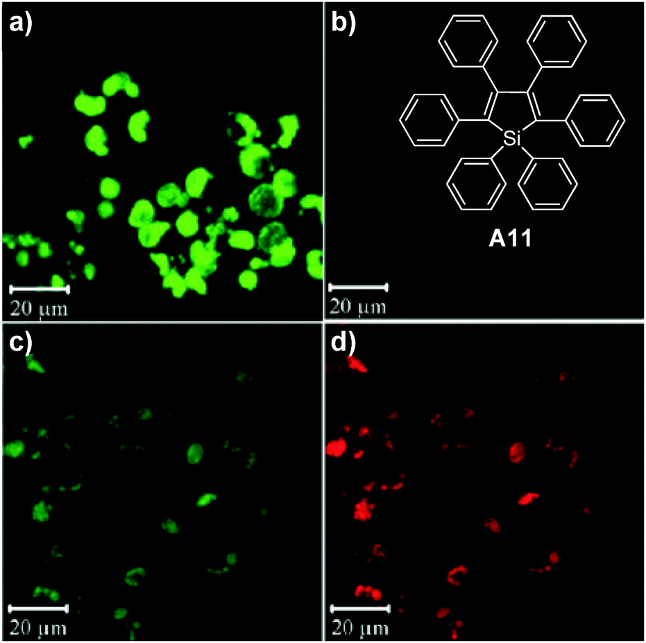 | ||
| Fig. 23 Chemical structure of A11. Confocal images of RAW cells incubated with PS-PMAA encapsulated (a) A11 nanoparticles, (b) A10 nanoparticles and (c and d) A10/A11 co-loaded nanoparticles. The images from the left column were obtained using the green fluorescence channel while the images from the right column were obtained using the red fluorescence channel under the same experimental conditions (reprinted with permission from ref. 143, Copyright 2010 Wiley-VCH). | ||
The studies in different groups clearly revealed that the structure and amphiphilicity of the block copolymers have a significant impact on the stability and brightness of the AIE nanoparticles. The lengths of the hydrophobic and hydrophilic components not only affect the nanoparticle size, but also their contact with AIE fluorogens. As compared to DSPE-PEG, the customized block copolymers offer tunable hydrophobic segments, which can entangle with the AIE fluorogens rather than through physical adsorption to yield more stable nanoparticles. As compared to the AIE fluorogen–polymer conjugate self-assembly, the encapsulation strategy also promotes well-controlled feeding ratio of AIE fluorogens to polymer matrices to yield optimized quantum yields in water. Amphiphilic polymers with better biocompatibility and different functional groups are expected to offer more choices for AIE nanoparticle fabrication.
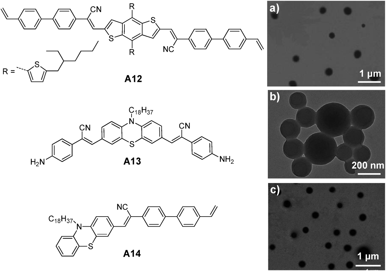 | ||
| Fig. 24 Chemical structures of A12, A13 and A14. TEM images of (a) A12, (b) A13 and (c) A14 nanoparticles prepared from RAFT, ring-opening polymerization and emulsion polymerization (reprinted with permission from ref. 146–148, Copyright 2013, 2014 and 2014 Royal Society of Chemistry). | ||
Tian and co-workers also reported the synthesis of amphiphilic polymers with AIE fluorogens at the side chain to facilitate self-assembly into nanoparticles for fluorescence imaging.150 The amphiphilic A15-containing polymers were obtained through polymerization among monomeric A15, N-(2-hydroxypropyl) methacrylamide (HPMA), [2-(methacryloyloxy)ethyl]trimethylammonium chloride (MATMA), and/or 2,2,2-trifluoroethyl methacrylate (TFEMA), as shown in Fig. 25. In water, the copolymers without TFEMA segments self-assembled into nanoparticles with average sizes of 7–9 nm, while the TFEMA-containing polymers led to AIE nanoparticles with average sizes of 21–25 nm by DLS. In the absence of TFEMA, the quantum yields of A15 nanoparticles were increased from 2% to 10% when the molar percentage of A15 in the copolymers was increased from 1 to 12 mol%. The presence of hydrophobic TFEMA in the polymer backbone significantly improved the quantum yield to 40%, once 1 mol% of A15 and 42.5 mol% of TFEMA were used for polymerization. This was due to the enhanced hydrophobicity of the TFEMA-containing polymer, which promoted compact aggregation of A15 in the core. Due to the presence of 19F in TFEMA, the AIE nanoparticles have great potential in dual-modality imaging applications. As such, in situ polymerization represents a general strategy to customize AIE nanoparticles with versatile functionalities through incorporation of desired reactive monomers.
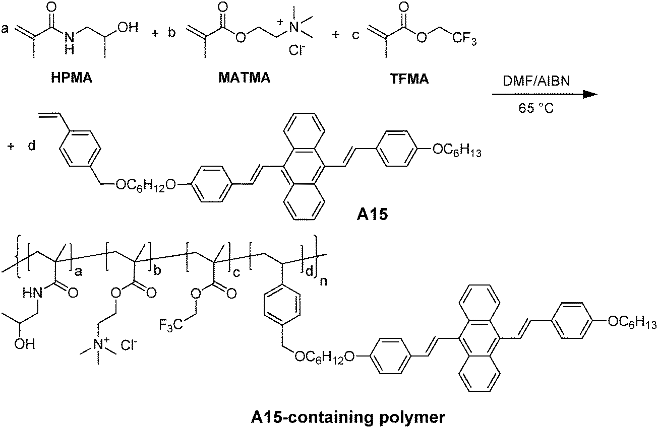 | ||
| Fig. 25 Synthetic route to the representative A15-containing amphiphilic polymer (reprinted with permission from ref. 150, Copyright 2012 Royal Society of Chemistry). | ||
AIE fluorogens with polymerizable functional groups (e.g. vinyl or bis-amine groups) could be used as monomers to yield AIE nanoparticles with large sizes in water (200–400 nm) through in situ polymerization with other encapsulation matrix precursors. The strategy is able to yield very stable nanoparticles and the content of AIE fluorogens in each nanoparticle could be fine-tuned by adjusting the AIE monomers in the feed. However, multiple synthetic steps are required for modifying each AIE fluorogen before polymerization, which adds complexity and cost to the AIE nanoparticle production. The size distribution and the surface of these nanoparticles also require further optimization before they could be used for more specific applications.
4. Photoacoustic imaging
Although fluorescence imaging techniques have shown high resolution and sensitivity, they lack good spatial resolution in in vivo applications due to limited penetration depth in animals. One solution is to develop multi-modal imaging probes through incorporation of other imaging modalities (such as MRI and radioactive agents) into the organic fluorescent probes. The alternative strategy is to explore new imaging modalities, such as photoacoustic (PA) imaging. Recently, PA imaging technology has emerged as a novel method that allows the visualization of optical reporter agents with never-seen-before performance. In particular, multispectral PA technology endows highly specific molecular imaging through several millimetres to centimetres of tissue with resolutions in the 20–200 μm range.151,152 The mechanism of PA imaging is based on the generation of acoustic waves following the absorption of light pulses of ultrashort duration. After the tissue is illuminated with light pulses, the fast absorption of light pulses by PA contrast agents in tissue enables the absorbed energy to undergo a thermoelastic expansion that emits mechanical waves at ultrasonic frequencies. These waves can subsequently be detected by acoustic detectors close to the illuminated tissue, which is followed by reconstruction of the images of absorbed energy in analogy to the formation of ultrasound images using appropriate mathematical methods.153,154To date, the most widely used PA contrast agents are gold nanomaterials including nanorods, nanocages and nanoshells.155–158 In addition, several reports have also utilized carbonous nanomaterials (such as carbon nanotubes and polyhydroxy fullerenes).159,160 The recent research interest in PA probe design has been extended to NIR dyes and organic nanoparticles due to their benign biocompatibility.161–165 As large NIR absorption coefficients and high nonradiative quantum yields are key features for organic materials to yield strong PA signals, efforts have been made to look for or design organic emitters with long wavelength absorption and maximized non-radiative pathways to achieve high non-radiative quantum yields for PA imaging.
Recently, CPs have emerged as a new class of organic agents for PA imaging. Initial studies were focused on polypyrrole (PPy) as the PA agent. PPy is a non-soluble CP with intense NIR absorption that has been widely used for organic electronics166,167 and biological applications.168–170 In 2013, Dai and co-workers reported the application of PPy nanoparticles (CP14) for brain vascular imaging in a living mouse model. The PPy nanoparticles were synthesized by aqueous phase polymerization using PVA as the stabilizing agent and FeCl3 as an oxidation catalyst.171 Due to the surface PVA molecules and their small size (diameter of ∼46 nm in water), the PPy nanoparticles were well dispersed in water with strong absorption in the 700–900 nm region. Upon illumination with an 808 nm pulse laser, the PA signals increased linearly with increasing concentrations of nanoparticles in water. Intravenous administration of PPy nanoparticles allowed imaging of the cerebral cortex of the mouse brain vasculature with greater clarity than the intrinsic signal from hemoglobin in blood. At 1 h post-injection, the PA signal remained essentially intense, indicating that a sufficient amount of PPy nanoparticles has long-circulating ability in blood (Fig. 26). Moreover, no acute toxicity to the vital organs (e.g., heart, liver, lung, spleen and kidney) was observed at 15 day post-injection, suggesting good biocompatibility of the PPy-PVA nanoparticles.
 | ||
| Fig. 26 Chemical structures of CP14 and CP15. (a) Photograph of the mouse brain obtained before the data acquisition for PAT. Non-invasive PAT imaging of a mouse brain in vivo at 5 min (b) and 60 min (c) post-injection of CP14 nanoparticles upon excitation at 808 nm (reprinted with permission from ref. 171, Copyright 2013 Royal Society of Chemistry). | ||
Although PPy nanoparticles have shown strong PA signals, PPy is not soluble in almost any organic solvent with very poor chemical processability. In addition, the PPy nanoparticles synthesized from in situ polymerization do not allow feasible surface modification as there is no surface functional group. To overcome this limitation, Liu and co-workers developed processable CP15 with NIR absorption and fabricated DSPE-PEG encapsulated CP15 nanoparticles through nanoprecipitation.172 In the molecular structure of CP15, the electron-deficient thiadiazoloquinoxaline acted as a good electron acceptor to ensure small band gap of the polymer with long wavelength absorption. The obtained CP15 nanoparticles have sizes of ∼50 nm under TEM, which showed strong absorbance in the NIR region with a high non-radiative quantum yield of almost 100%, suggesting that most of the excited excitons returned to the ground state via the non-radiative decay pathway. When CP15 nanoparticles were continuously irradiated with a fixed laser fluence of 15 mJ cm−2, no significant absorbance change was observed in 6 min. This compared favourably with Au nanorods, which showed an ∼60% decrease in absorbance within 5 seconds under the same laser irradiation. In vivo rat brain vascular imaging highlighted the good PA contrast of CP15 nanoparticles in blood, revealing that the PA intensity was improved by ∼3-fold after nanoparticle injection as compared to the intrinsic signal upon excitation at 808 nm. Overall, the intense NIR absorption, high non-radiative quantum yield, excellent photostability and low cytotoxicity of CP15 nanoparticles highlight the great potential of processable CP nanoparticles for in vivo PA imaging. Further encapsulation of CP15 with DSPE-PEG-folate as the matrix yielded CP based PA probes for targeted tumor imaging and direct visualization of nanoparticle biodistribution in different organs.
Rao and co-workers further developed activatable photoacoustic probes using CP16 for in vitro and in vivo imaging of reactive oxygen species (ROS).173CP16 and CP17 nanoparticles were prepared through nanoprecipitation assisted by 1,2-dipalmitoyl-sn-glycero-3-phosphocholine, resulting in CP nanoparticles with average diameters of ∼40 nm by TEM. As compared to CP17 nanoparticles, the narrower PA spectra and five-fold greater PA amplitude make CP16 nanoparticles a better PA imaging probe. On a per mass basis, the PA signal of CP16 nanoparticles in living mice was ∼4.0 and 5.8 times higher than that of single-walled carbon nanotubes and gold nanorods upon excitation at 700 nm. Through co-precipitation of CP16 nanoparticles with IR775, the nanoparticles showed three maxima at 700, 735 and 820 nm in the photoacoustic spectrum with nearly the same amplitude (Fig. 27b). In the presence of ONOO− and ClO−, the photoacoustic peaks at 735 nm and 820 nm decreased significantly, while the peak at 700 nm remained nearly the same. The obvious change for the peak at 820 nm was attributed to the ROS-mediated rapid oxidative decomposition of IR775. As a result, the dual-peak ratiometric changes (PA700/PA800) provided a clear signal for ONOO− and ClO− detection. The successful demonstration of ratiometric PA imaging of ROS in living mice offers new opportunities for advanced PA molecular imaging, which has great potential in preclinical investigation and clinical translation of physiological and pathological processes.
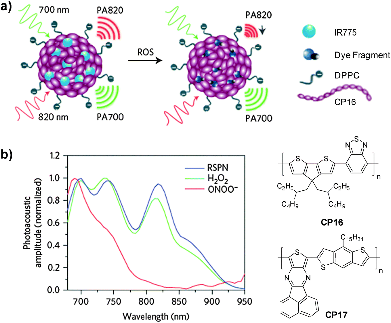 | ||
| Fig. 27 Chemical structures of CP16 and CP17. (a) Schematic illustration of the CP16/IR775 nanoparticles for ROS detection. (b) Representative photoacoustic spectra of CP16/IR775 nanoparticles in the absence and presence of ROS (reprinted with permission from ref. 173, Copyright 2014 Nature Publishing Group). | ||
Although at the initial stage, NIR absorbing CPs have been demonstrated to be a new class of promising agents for PA imaging with high signal output and good photostability. The chemical stability (e.g., stable PA signal in the presence of ROS) also inspires new research directions in CP nanoparticle based PA molecular imaging. As compared to traditional PA imaging agents with large NIR absorption (e.g., gold nanorods, gold cages), the feasible polymer encapsulation procedures can easily endow the CP nanoparticles with different surface functionalities for targeted imaging. It is also important to note that simultaneous fluorescence and PA signals could be generated from single CP based nanoparticles, which is useful for self-validation in target sensing and imaging.173
5. Concluding remarks and perspectives
In this review, recent progress of polymer-encapsulated organic nanoparticles using CPs and AIE fluorogens as the emitters for fluorescence and photoacoustic imaging has been summarized. The polymer encapsulation strategy has been proved to be simple and effective in quickly transforming organic soluble molecules into aqueous media, and for fast screening of them for various biological applications. For fluorescence imaging, the brightness, stability, toxicity, size and biodegradability (or body clearance) of the nanoparticles are of major concern. Strategies such as incorporating bulky groups into the polymer backbone and side chains, introducing moieties to induce intramolecular and intermolecular energy transfer and controlling the polymer self-assembly in aggregates are effective in reducing aggregation caused quenching of CP nanoparticles. In addition, recent advances in the development of AIE fluorogens show great potential in constructing highly fluorescent nanoparticles as they take advantage of the natural aggregation process to increase the fluorescence. It has been reported that even for the same emitter, encapsulating them into different matrices can affect their molecular packing, aggregation, and distribution in the formed nanoparticles. Careful selection of the polymer matrix and fine-tuning the matrix to emitter ratio thus not only affect sizes, but also brightness and stability of the nanoparticles. Polymer encapsulated nanoparticles with sizes from a few to several hundreds of nanometers have been reported and versatile surface functional groups have been customized to cater to specific imaging tasks, such as organelle imaging, targeted in vitro and in vivo tumor imaging, cancer cell tracing, blood vessel imaging, and even specific chemical and biomolecular species imaging. As shown in Table 3, single particle analysis for both CP and AIE nanoparticles reveals that they could be designed to have higher brightness than commercially available polymer encapsulated quantum dots with a similar dimension. In addition, most of the reported polymer encapsulated organic nanoparticles show good physical stability, which has been further improved when chemical bonds are introduced to cross link the matrices and the emitters through either post-modification or in situ polymerization. Although the photostability of these nanoparticles is primarily determined by the emitters themselves, encapsulating them into the polymeric shells could obviously improve their stability against photobleaching. Additional advantages of these nanoparticles also include their excellent biocompatibility, good cellular permeability and low cytotoxicity, which have been demonstrated for almost all the reported CP and AIE nanoparticles in vitro. However, systematic investigation of their in vivo toxicity, biodistribution and biodegradability remains to be explored.| NPsa | Size (nm) | Photostability | Physical/chemical stability | QYb | Fluorescence or PA signal | Ref. |
|---|---|---|---|---|---|---|
| a NP: nanoparticle. b QY: quantum yield. c NR: nanorod. d DMEM: Dulbecco's modified Eagle's medium. e SWNT: single wall nanotube. | ||||||
| CP6 PS-PEG | ∼15 | Obvious fluorescence intermittence (blinking) for Qdot 565 and Alexa 488 and stable emission for CP6 nanoparticles (λex = 488 nm, 1 mW) | Clear nanoparticle suspension after storage for 6 months | 0.3 | The single CP6 nanoparticle was ∼30 times brighter than Qdot 565 and Alexa 488 upon excitation at 488 nm (4 mW) | 71 |
| Qdot 565 | ∼15 | — | 0.3 | |||
| −0.5 | ||||||
| Alexa 488 | ∼1 | — | 0.9 | |||
| CP6 F127-SiO2 | ∼12 | Better photostability for F127-SiO2 nanoparticles than DSPE-PEG encapsulated ones | Stable emission in PBS buffer for 10 days | 0.75 | Single CP6 nanoparticle emitted ∼3.4 fold more photons compared to each Qdot 655 | 119 |
| CP6 DSPE-PEG | ∼30 | 0.40 | ||||
| Qdot 655 | — | 0.15 | ||||
| A6 DSPE-PEG | ∼30 | Comparable photostability for A6 nanoparticles and Qtracker 655 upon excitation at 514 nm (2 mW) | Constant emission intensity in DMEMd for 9 days | 0.24 | The single A6 nanoparticle was ∼15-fold brighter than Qtracker 655 upon excitation at 488 nm | 132 |
| QD 655 | — | The emission dropped to 30% of its initial intensity in DMEM for 9 days | 0.15 | |||
| CP15 DSPE-PEG | ∼80 | Upon continuous laser irradiation (15 mJ cm−2), no obvious change in absorbance was observed for CP15 nanoparticles in 6 minutes while a 60% decrease in absorbance at 800 nm was observed for Au NRs within 5 seconds | — | <0.01 | An ∼3-fold higher PA signal was observed in the brain vasculature upon CP15 nanoparticle injection (λex = 808 nm) | 172 |
| Au NRsc | — | — | — | |||
| CP16 DSPE-PEG | ∼40 | Upon continuous laser irradiation at 9 mJ cm−2 (700 nm), stable PA signal for CP16 nanoparticles and ∼30% decrease of the PA signal for AuNRs within minutes | Stable PA signal in the presence of ROS | — | CP16 nanoparticles in living mice showed ∼4.0 and 5.8 times higher PA signal as compared to SWNTs and Au NRs on a per mass basis, upon excitation at 700 nm | 173 |
| Au NRs | — | — | — | |||
| SWNTse | — | — | — | |||
The recent discovery that CPs are active agents in PA imaging has significantly broadened their biomedical applications. This is also very exciting from the materials point of view. Despite the fact that great efforts have been made to develop highly fluorescent CPs for sensing and imaging applications, many existing CPs, such as those with FR/NIR absorption, are not very emissive, especially in the aggregated states. The emitters with strong NIR absorption and active non-radiative decay thus opened a new window for PA imaging. On a par mass basis, the PA signals from CP nanoparticles are even higher than those for the most widely used PA contrast agents, such as Au nanorods and single-walled carbon nanotubes (Table 3). In addition, as non-radiative pathway is easily associated with heat generation, photoacoustic agents also have great potential to be used for photothermal therapy (PTT), which is a highly specific, low toxic and noninvasive strategy for cancer and tumor ablation.174 Several CPs with FR/NIR absorption have also been demonstrated to be effective photothermal agents for imaging guided photothermal treatment of tumors.175,176 As the application of CPs in PA imaging and photothermal treatment is at the very early stage, the design principles for such nanoparticles and their operation mechanisms are not fully established. Nonetheless, the reported few examples have successfully demonstrated that CP based polymeric nanoparticles are very promising for deep in vivo tumor imaging and PTT with minimized side effects on normal tissues.171–176
Future work of polymer encapsulated organic nanoparticles will be directed toward the development of smart and stimuli responsive imaging and therapy systems. Further development of CP and AIE fluorogens for biomedical applications will be mainly focused on the FR/NIR emitters with narrow band emission. Various signal amplification strategies, such as FRET and metal-enhanced fluorescence, could be used to further improve their brightness for fluorescence imaging. Similarly, further development of CP and AIE nanoparticle based multimodal probes will be ideal for in vitro and in vivo imaging applications, which will provide much higher sensitivity and accuracy with the complementary information provided by each imaging modality. In addition, when properly designed, a single emitter might be able to simultaneously show capabilities of fluorescence imaging, PA imaging and PTT effect, which will provide unprecedented simplicity in designing a single component based multimodality image-guided therapy agent. To fine-tune the size and fluorescence of such nanoparticles, more functionalized biodegradable polymeric shells will be developed to help deliver the imaging and therapeutic agents. For example, light, enzyme or pH responsive polymeric shells will be developed for targeted and responsive tumor imaging, while cross-linkable polymer matrices will be synthesized to further improve the stability and photostability of these nanoparticles. As most of the polymer matrices used in current studies are from commercial sources, more synthetic biocompatible polymers with adjustable lengths of the hydrophobic and hydrophilic domains are expected to lead to better control of the sizes and stability of the nanoparticles. The progress in molecular design, matrix selection, mechanism study, biological markers together with more detailed metabolic process and long term in vivo toxicity evaluation will provide more fundamental information and open new research opportunities for polymer encapsulated organic nanoparticles in biomedical applications and for potential clinical translation.
Acknowledgements
The authors are grateful to the A*STAR Joint Council Office and Institute of Materials Research and Engineering of Singapore (IMRE/12-8P1103, IMRE/13-8P1104), the Singapore National Research Foundation (R279-000-390-281), the Singapore Ministry of Defense (R279-000-340-232), and SMART (R279-000-378-592) for financial support.Notes and references
- F. Leblond, S. C. Davis, P. A. Valdés and B. W. Poque, J. Photochem. Photobiol., B, 2010, 98, 77–94 CrossRef CAS PubMed.
- V. R. Kondepati, H. M. Heise and J. Backhaus, J. Anal. Bioanal. Chem., 2008, 390, 125–139 CrossRef CAS PubMed.
- M. F. Kircher, S. S. Gambhir and J. Grimm, Nat. Rev. Clin. Oncol., 2011, 8, 677–688 CrossRef CAS PubMed.
- R. Y. Tsien, Annu. Rev. Biochem., 1998, 67, 509–544 CrossRef CAS PubMed.
- S. van de Linde, M. Heilemann and M. Sauer, Annu. Rev. Phys. Chem., 2012, 63, 519–540 CrossRef CAS PubMed.
- M. De, P. S. Ghosh and V. M. Rotello, Adv. Mater., 2008, 20, 4225–4241 CrossRef CAS.
- M. Chen and M. Yin, Prog. Polym. Sci., 2014, 39, 365–395 CrossRef CAS PubMed.
- A. M. Smith, H. Duan, A. M. Mohs and S. Nie, Adv. Drug Delivery Rev., 2008, 60, 1226–1240 CrossRef CAS PubMed.
- J. P. Wilcoxon and B. L. Abrams, Chem. Soc. Rev., 2006, 35, 1162–1194 RSC.
- F. Wang and X. Liu, Chem. Soc. Rev., 2009, 38, 976–989 RSC.
- S. N. Baker and G. A. Baker, Angew. Chem., Int. Ed., 2010, 49, 6726–6744 CrossRef CAS PubMed.
- L. Wang, W. Zhao and W. Tan, Nano Res., 2008, 1, 99–115 CrossRef CAS.
- G. Feng, J. Liang and B. Liu, Macromol. Rapid Commun., 2013, 34, 705–715 CrossRef CAS PubMed.
- Y. Liu, K. Ai, X. Cheng, L. Huo and L. H. Lu, Adv. Funct. Mater., 2010, 20, 951–956 CrossRef CAS.
- J. Yan, M. C. Estévez, J. E. Smith, K. Wang, X. He, L. Wang and W. Tan, Nano Today, 2007, 2, 44–50 CrossRef.
- Advanced Fluorescence Reporters in Chemistry and Biology I, ed. A. P. Demchenko, Springer, 2010 Search PubMed.
- S. Luo, E. Zhang, Y. Su, T. Cheng and C. Shi, Biomaterials, 2011, 32, 7127–7138 CrossRef CAS PubMed.
- Photophysics of Aromatic Molecules, ed. J. B. Birks, Wiley-Interscience, London, 1970 Search PubMed.
- J. O. Escobedo, O. Rusin, S. Lim and R. M. Strongin, Curr. Opin. Chem. Biol., 2010, 14, 64–70 CrossRef CAS PubMed.
- D. Wang, J. Qian, S. He, J. S. Park, K.-S. Lee, S. Han and Y. Mu, Biomaterials, 2011, 32, 5880–5888 CrossRef CAS PubMed.
- L. Wang, C. Y. Yang and W. Tan, Nano Lett., 2005, 5, 37–43 CrossRef CAS PubMed.
- L. Wang and W. H. Tan, Nano Lett., 2006, 6, 84–88 CrossRef CAS PubMed.
- Y. Hong, J. W. Y. Lam and B. Z. Tang, Chem. Soc. Rev., 2011, 40, 5361–5388 RSC.
- Conjugated Polymers: A Practical Guide to Synthesis, ed. K. Müllen, J. R. Reynolds and T. Masuda, RSC, 2014 Search PubMed.
- D. T. McQuade, A. E. Pullen and T. M. Swager, Chem. Rev., 2000, 100, 2537–2574 CrossRef CAS PubMed.
- Conjugated Polyelectrolytes: Fundamentals and Applications, ed. B. Liu and G. C. Bazan, Wiley, 2013 Search PubMed.
- C. Zhu, L. Liu, Q. Yang, F. Lv and S. Wang, Chem. Rev., 2012, 112, 4687–4735 CrossRef CAS PubMed.
- B. Liu and G. C. Bazan, Chem. Mater., 2004, 16, 4467–4476 CrossRef CAS.
- K. Y. Pu and B. Liu, Adv. Funct. Mater., 2011, 21, 3408–3423 CrossRef CAS.
- A. Duarte, K. Y. Pu, B. Liu and G. C. Bazan, Chem. Mater., 2011, 23, 501–505 CrossRef CAS.
- C. Wu and D. T. Chiu, Angew. Chem., Int. Ed., 2013, 52, 3086–3109 CrossRef CAS PubMed.
- L. Feng, C. Zhu, H. Yuan, L. Liu, F. Lv and S. Wang, Chem. Soc. Rev., 2013, 42, 6620–6633 RSC.
- K. Li and B. Liu, J. Mater. Chem., 2012, 22, 1257–1264 RSC.
- K. Y. Pu and B. Liu, Biosens. Bioelectron., 2009, 24, 1067–1073 CrossRef CAS PubMed.
- Y. Wang and B. Liu, Curr. Org. Chem., 2011, 15, 446–464 CrossRef CAS.
- J. Pecher and S. Mecking, Chem. Rev., 2010, 110, 6260–6279 CrossRef CAS PubMed.
- D. Tuncel and H. V. Demir, Nanoscale, 2010, 2, 484–494 RSC.
- H. Jiang, P. Taranekar, R. Reynolds and K. S. Schanze, Angew. Chem., Int. Ed., 2009, 48, 4300–4316 CrossRef CAS PubMed.
- K. Li, K. Y. Pu, L. P. Cai and B. Liu, Chem. Mater., 2011, 23, 2113–2119 CrossRef CAS.
- C. W. C. Szymanski, Z. Cain and J. McNeill, J. Am. Chem. Soc., 2007, 129, 12904–12905 CrossRef PubMed.
- C. Szymanski, C. Wu, J. Hooper, M. A. Salazar, A. Perdomo, A. Dukes and J. McNeill, J. Phys. Chem. B, 2005, 109, 8543–8546 CrossRef CAS PubMed.
- D. Ding, K. Li, B. Liu and B. Z. Tang, Acc. Chem. Res., 2013, 46, 2441–2453 CrossRef CAS PubMed.
- C. Kim, C. Favazza and L. V. Wang, Chem. Rev., 2010, 110, 2756–2782 CrossRef CAS PubMed.
- P. K. Kandel, L. P. Fernando, P. C. Ackroyd and K. A. Christensen, Nanoscale, 2011, 3, 1037–1045 RSC.
- Y. Liu and S. S. Feng, J. Controlled Release, 2011, 152, e64–e65 CrossRef CAS PubMed.
- Z. Zhang and S. S. Feng, Biomaterials, 2006, 27, 262–270 CrossRef CAS PubMed.
- M. J. Joralemon, S. Mcrae and T. Emrick, Chem. Commun., 2010, 46, 1377–1393 RSC.
- G. Gaucher, R. H. Marchessault and J. C. Leroux, J. Controlled Release, 2010, 143, 2–12 CrossRef CAS PubMed.
- J. Su, J. Chen, F. Zeng, Q. Chen, S. Wu and Z. Tong, Polym. Bull., 2008, 61, 425–434 CrossRef CAS.
- J. Chen, P. Zhang, G. Fang, P. Yi, X. Yu, X. Li, F. Zeng and S. Wu, J. Phys. Chem. B, 2011, 115, 3354–3362 CrossRef CAS PubMed.
- J. Chen, F. Zeng, S. Wu, J. Su and Z. Tong, Small, 2009, 5, 970–978 CrossRef CAS PubMed.
- S. Wang, G. Kim, Y.-E. K. Lee, H. J. Hah, M. Ethirajan, R. K. Pandey and R. Kopelman, ACS Nano, 2012, 6, 6843–6851 CrossRef CAS PubMed.
- Handbook on Applications of Ultrasound: Sonochemistry for Sustainability, ed. D. Chen, S. K. Sharma and A. Mudhoo, CRC Press, 2011 Search PubMed.
- S. Hornig, T. Heinze, C. R. Becer and U. S. Schubert, J. Mater. Chem., 2009, 19, 3838–3840 RSC.
- R. Jakubiak, C. J. Collison, W. C. Wan, L. J. Rothberg and B. R. Hsieh, J. Phys. Chem. A, 1999, 103, 2394–2398 CrossRef CAS.
- H. Jiang, X. Y. Zhao and K. S. Schanze, Langmuir, 2007, 23, 9481–9486 CrossRef CAS PubMed.
- S. W. Thomas III, G. D. Joly and T. M. Swager, Chem. Rev., 2007, 107, 1339–1386 CrossRef PubMed.
- C. Qin, X. Wu, H. Tong and L. Wang, J. Mater. Chem., 2010, 20, 7957–7964 RSC.
- S. Xiao, M. Nguyen, X. Gong, Y. Cao, H. Wu, D. Moses and A. J. Heeger, Adv. Funct. Mater., 2003, 13, 25–29 CrossRef CAS.
- J. Liu, G. Feng, D. Ding and B. Liu, Polym. Chem., 2013, 4, 4326–4334 RSC.
- K. Y. Pu, K. Li and B. Liu, Adv. Funct. Mater., 2010, 20, 2770–2777 CrossRef CAS.
- Y. H. Jin, F. Ye, M. Zeigler, C. Wu and D. T. Chiu, ACS Nano, 2011, 5, 1468–1475 CrossRef CAS PubMed.
- L. Yuan, W. Lin, K. Zheng, L. He and W. Huang, Chem. Soc. Rev., 2013, 42, 622–661 RSC.
- S. Kim, C.-K. Lim, J. Na, Y.-D. Lee, K. Kim, K. Choi, J. F. Leary and I. C. Kwon, Chem. Commun., 2010, 46, 1617–1619 RSC.
- J. Liu, J. Geng and B. Liu, Chem. Commun., 2013, 49, 1491–1493 RSC.
- X. Y. Zhao, M. R. Pinto, L. M. Hardison, J. Mwaura, J. Müller, H. Jiang, D. Witker, V. D. Kleiman, J. R. Reynolds and K. S. Schanze, Macromolecules, 2006, 39, 6355–6366 CrossRef CAS.
- Y.-H. Chan, F. Ye, M. E. Gallina, X. Zhang, Y. Jin, I.-C. Wu and D. T. Chiu, J. Am. Chem. Soc., 2012, 134, 7309–7312 CrossRef CAS PubMed.
- X. Zhang, J. Yu, Y. Rong, F. Ye, D. T. Chiu and K. Uvdal, Chem. Sci., 2013, 4, 2143–2151 RSC.
- C. Wu, B. Bull, C. Szymanski, K. Christensen and J. McNeill, ACS Nano, 2008, 2, 2415–2423 CrossRef CAS PubMed.
- K. Li, J. Pan, S. S. Feng, A. W. Wu, K. Y. Pu, Y. T. Liu and B. Liu, Adv. Funct. Mater., 2009, 19, 3535–3542 CrossRef CAS.
- C. Wu, T. Schneider, M. Zeigler, J. Yu, P. G. Schiro, D. R. Burnham, J. D. McNeill and D. T. Chiu, J. Am. Chem. Soc., 2010, 132, 15410–15417 CrossRef CAS PubMed.
- M. B. Zeigler, W. Sun, Y. Rong and D. T. Chiu, J. Am. Chem. Soc., 2013, 135, 11453–11455 CrossRef CAS PubMed.
- L. Brannon-Peppas and J. O. Blanchette, Adv. Drug Delivery Rev., 2004, 56, 1649–1659 CrossRef CAS PubMed.
- D. Klose, F. Siepmann, K. Elkharraz and J. Siepmann, Int. J. Pharm., 2008, 354, 95–103 CrossRef CAS PubMed.
- F. Danhier, E. Ansorena, J. M. Silva, R. Coco, A. Le Breton and V. Préat, J. Controlled Release, 2012, 161, 505–522 CrossRef CAS PubMed.
- C. Wu, H. Peng, Y. Jiang and J. McNeill, J. Phys. Chem. B, 2006, 110, 14148–14154 CrossRef CAS PubMed.
- K. Li, Y. T. Liu, K. Y. Pu, S. S. Feng, R. Y. Zhan and B. Liu, Adv. Funct. Mater., 2011, 21, 287–294 CrossRef CAS.
- B. Liu and G. C. Bazan, J. Am. Chem. Soc., 2004, 126, 1942–1943 CrossRef CAS PubMed.
- K.-Y. Pu and B. Liu, Macromolecules, 2008, 41, 6636–6640 CrossRef CAS.
- D. Yu, Y. Zhang and B. Liu, Macromolecules, 2008, 41, 4003–4011 CrossRef CAS.
- K. Li, R. Y. Zhan, S. S. Feng and B. Liu, Anal. Chem., 2011, 83, 2125–2132 CrossRef CAS PubMed.
- H. Xu, M. Y. Sha, E. Y. Wong, J. Uphoff, Y. Xu, J. A. Treadway, A. Truong, E. O. Brien, S. Asquith, M. Stubbins, N. K. Spurr, E. H. Lai and W. Mahoney, Nucleic Acids Res., 2003, 31, e43 CrossRef PubMed.
- M. Liong, J. Lu, M. Kovochich, T. Xia, S. G. Ruehm, A. E. Nel, F. Tamanoi and J. L. Zink, ACS Nano, 2008, 2, 889–896 CrossRef CAS PubMed.
- P. Howes, M. Green, A. Bowers, D. Parker, G. Varma, M. Kallumadil, M. Hughes, A. Warley, A. Brain and R. Botnar, J. Am. Chem. Soc., 2010, 132, 9833–9842 CrossRef CAS PubMed.
- B. Sun, M. J. Sun, Z. Gu, Q.-D. Shen, S.-J. Jiang, Y. Xu and Y. Wang, Macromolecules, 2010, 43, 10348–10354 CrossRef CAS.
- K. Li, D. Ding, D. Huo, K. Y. Pu, N. N. P. Thao, Y. Hu, Z. Li and B. Liu, Adv. Funct. Mater., 2012, 22, 3107–3115 CrossRef CAS.
- X. Gao, L. Yang, J. A. Petros, F. F. Marshall, J. W. Simons and S. Nie, Curr. Opin. Biotechnol., 2005, 16, 63–72 CrossRef CAS PubMed.
- J. Geng, K. Li, K. Y. Pu, D. Ding and B. Liu, Small, 2012, 8, 2421–2429 CrossRef CAS PubMed.
- T. Chen, M. X. Yang, X. J. Wang, L. H. Tan and H. Y. Chen, J. Am. Chem. Soc., 2008, 130, 11858–11859 CrossRef CAS PubMed.
- J. Yang, C. H. Lee, J. Park, S. Seo, E. K. Lim, Y. J. Song, J. S. Suh, H. G. Yong, Y. M. Huh and S. Haam, J. Mater. Chem., 2007, 17, 2695–2699 RSC.
- R. Wang, R. Xiao, Z. Zeng, L. Xu and J. Wang, Int. J. Nanomed., 2012, 7, 4185–4198 CAS.
- P. Howes, M. Green, J. Levitt, K. Suhling and M. Hughes, J. Am. Chem. Soc., 2010, 132, 3989–3996 CrossRef CAS PubMed.
- K. Y. Pu, L. Cai and B. Liu, Macromolecules, 2009, 42, 5933–5940 CrossRef CAS.
- D. Ding, J. Liu, G. Feng, K. Li, Y. Hu and B. Liu, Small, 2013, 9, 3093–3102 CrossRef CAS PubMed.
- G. Feng, K. Li, J. Liu, D. Ding and B. Liu, Small, 2014, 10, 1212–1219 CrossRef CAS PubMed.
- K. Pu, A. J. Shuhendler and J. Rao, Angew. Chem., Int. Ed., 2013, 125, 10515–10519 CrossRef.
- K. Maruyama, T. Yuda, A. Okamoto, S. Kojima, A. Suqinaka and M. Lwatsuru, Biochim. Biophys. Acta, 1992, 1128, 44–49 CrossRef CAS.
- C. Wu, Y. Jin, T. Schneider, D. R. Burnham, P. B. Smith and D. T. Chiu, Angew. Chem., Int. Ed., 2010, 49, 9436–9440 CrossRef CAS PubMed.
- F. Ye, C. Wu, Y. Jin, M. Wang, Y.-H. Chan, J. Yu, W. Sun, S. Hayden and D. T. Chiu, Chem. Commun., 2012, 48, 1778–1780 RSC.
- S. R. Amrutha and M. Jayakannan, J. Phys. Chem., 2008, 112, 1119–1129 CrossRef CAS PubMed.
- K. Li and B. Liu, Polym. Chem., 2010, 1, 252–259 RSC.
- K. Jeong, S. Park, Y.-D. Lee, C.-K. Lim, J. Kim, B. H. Chung, I. C. Kwon, C. R. Park and S. Kim, Adv. Mater., 2013, 25, 5574–5580 CrossRef CAS PubMed.
- Z. Tian, J. Yu, C. Wu, C. Szymanski and J. McNeill, Nanoscale, 2010, 2, 1999–2011 RSC.
- F. Ye, C. Wu, Y. Jin, Y.-H. Chan, X. Zhang and D. T. Chiu, J. Am. Chem. Soc., 2011, 133, 8146–8149 CrossRef CAS PubMed.
- Y.-H. Chan, C. Wu, F. Ye, Y. Jin, P. B. Smith and D. T. Chiu, Anal. Chem., 2011, 83, 1448–1455 CrossRef CAS PubMed.
- M. Irie, T. Fukaminato, T. Sasaki, N. Tamai and T. Kawai, Nature, 2002, 420, 759–760 CrossRef CAS PubMed.
- M. Hofmann, C. Eggeling, S. Jakobs and S. W. Hell, Proc. Natl. Acad. Sci. U. S. A., 2005, 102, 17565–17569 CrossRef CAS PubMed.
- R. Ando, H. Mizuno and A. Miyawaki, Science, 2004, 306, 1370–1373 CrossRef CAS PubMed.
- Y. Osakada, L. Hanson and B. Cui, Chem. Commun., 2012, 48, 3285–3287 RSC.
- G. Feng, D. Ding, K. Li, J. Liu and B. Liu, Nanoscale, 2014, 6, 4141–4147 RSC.
- Y.-H. Chan, M. E. Gallina, X. Zhang, I.-C. Wu, Y. Jin, W. Sun and D. T. Chiu, Anal. Chem., 2012, 84, 9431–9438 CAS.
- C. Wu, S. J. Hansen, Q. Hou, J. Yu, M. Zeigler, Y. H. Jin, D. R. Burnham, J. D. McNeill, J. M. Olson and D. T. Chiu, Angew. Chem., Int. Ed., 2011, 50, 3430–3434 CrossRef CAS PubMed.
- A. L. Koner, D. Krndija, Q. Hou, D. J. Sherratt and M. Howarth, ACS Nano, 2013, 7, 1137–1144 CrossRef CAS PubMed.
- Tissue optics, ed. V. Tuchin, SPIE Press, Bellingham, Washington, 2000 Search PubMed.
- M.-K. So, C. Xu, A. M. Loening, S. S. Gambhir and J. Rao, Nat. Biotechnol., 2006, 24, 339–343 CrossRef CAS PubMed.
- L. Xiong, A. J. Shuhendler and J. Rao, Nat. Commun., 2012, 3, 1193 CrossRef PubMed.
- Y. Jin, F. Ye, C. Wu, Y.-H. Chan and D. T. Chiu, Chem. Commun., 2012, 48, 3161–3163 RSC.
- J. Geng, C. C. Goh, N. Tomczak, J. Liu, R. Liu, L. Ma, L. G. Ng, G. G. Gurzadyan and B. Liu, Chem. Mater., 2014, 26, 1874–1880 CrossRef CAS.
- H. Tan, Y. Zhang, M. Wang, Z. Zhang, X. Zhang, A. M. Yong, S. Y. Wong, A. Y. Chang, Z. K. Chen, X. Li, M. Choolani and J. Wang, Biomaterials, 2012, 33, 237–246 CrossRef CAS PubMed.
- D. Polli, G. Grancini, J. Clark, M. Celebrano, T. Virgili, G. Cerullo and G. Lanzani, Adv. Mater., 2010, 22, 3048–3051 CrossRef CAS PubMed.
- Z. Chi, X. Zhang, B. Xu, X. Zhou, C. Ma, Y. Zhang, S. Liu and J. Xu, Chem. Soc. Rev., 2012, 41, 3878–3896 RSC.
- J. Luo, Z. Xie, J. W. Y. Lam, L. Cheng, H. Chen, C. Qiu, H. S. Kwok, X. Zhan, Y. Liu, D. Zhu and B. Z. Tang, Chem. Commun., 2001, 18, 1740–1741 RSC.
- Y. Hong, J. W. Y. Lam and B. Z. Tang, Chem. Commun., 2009, 4332–4353 RSC.
- G. Qian and Z. Y. Wang, Chem. – Asian J., 2010, 5, 1006–1029 CrossRef CAS PubMed.
- F. Ito, R. Ohta, Y. Yokota, K. Ueno, H. Misawa and T. Nagamura, Opt. Photonics J., 2013, 3, 27–31 CrossRef CAS.
- Q. Zhao, K. Li, S. Chen, A. Qin, D. Ding, S. Zhang, Y. Liu, B. Liu, J. Z. Sun and B. Z. Tang, J. Mater. Chem., 2012, 22, 15128–15135 RSC.
- W. Qin, D. Ding, J. Liu, W. Z. Yuan, Y. Hu, B. Liu and B. Z. Tang, Adv. Funct. Mater., 2012, 22, 771–779 CrossRef CAS.
- Z. Wang, S. Chen, J. W. Y. Lam, W. Qin, R. T. K. Kwok, N. Xie, Q. Hu and B. Z. Tang, J. Am. Chem. Soc., 2013, 135, 8238–8245 CrossRef CAS PubMed.
- X. Zhang, X. Zhang, B. Yang, M. Liu, W. Liu, Y. Chen and Y. Wei, Polym. Chem., 2013, 4, 4317–4321 RSC.
- Frontiers in Chemical Sensors: Novel Principles and Techniques, ed. G. Orellana and M. C. Moreno-Bondi, Springer, Berlin, 2010 Search PubMed.
- K. Li, Y. Jiang, D. Ding, X. Zhang, Y. Liu, J. Hua, S. S. Feng and B. Liu, Chem. Commun., 2011, 47, 7323–7325 RSC.
- K. Li, W. Qin, D. Ding, N. Tomczak, J. Geng, R. Liu, J. Liu, X. Zhang, H. Liu, B. Liu and B. Z. Tang, Sci. Rep., 2013, 3, 1150 CAS.
- D. Wang, J. Qian, W. Qin, A. Qin, B. Z. Tang and S. He, Sci. Rep., 2014, 4, 4279 Search PubMed.
- K. Li, Z. Zhu, P. Cai, R. Liu, N. Tomczak, D. Ding, J. Liu, W. Qin, Z. Zhao, Y. Hu, X. Chen, B. Z. Tang and B. Liu, Chem. Mater., 2013, 25, 4181–4187 CrossRef CAS.
- K. Li, D. Ding, C. Prashant, W. Qin, C.-T. Yang, B. Z. Tang and B. Liu, Adv. Healthcare Mater., 2013, 2, 1600–1605 CrossRef CAS PubMed.
- W. Qin, K. Li, G. Feng, M. Li, Z. Yang, B. Liu and B. Z. Tang, Adv. Funct. Mater., 2014, 24, 635–643 CrossRef CAS.
- D. Ding, C. C. Goh, G. Feng, Z. Zhao, J. Liu, R. Liu, N. Tomczak, J. Geng, B. Z. Tang, L. G. Ng and B. Liu, Adv. Mater., 2013, 25, 6083–6088 CrossRef CAS PubMed.
- Z. Xie, B. Yang, W. Xie, L. Liu, F. Shen, H. Wang, X. Yang, Z. Wang, Y. Li, M. Hanif, G. Yang, L. Ye and Y. Ma, J. Phys. Chem. B, 2006, 110, 20993–21000 CrossRef CAS PubMed.
- J. Geng, Z. Zhu, W. Qin, L. Ma, Y. Hu, G. G. Gurzadyan, B. Z. Tang and B. Liu, Nanoscale, 2014, 6, 939–945 RSC.
- Y. Dong, B. Xu, J. Zhang, X. Tan, L. Wang, J. Chen, H. Lv, S. Wen, B. Li, L. Ye, B. Zou and W. Tian, Angew. Chem., Int. Ed., 2012, 51, 10782–10785 CrossRef CAS PubMed.
- J. Geng, K. Li, W. Qin, L. Ma, G. G. Gurzadyan, B. Z. Tang and B. Liu, Small, 2013, 9, 2012–2019 CrossRef CAS PubMed.
- Y. Yang, F. An, Z. Liu, X. Zhang, M. Zhou, W. Li, X. Hao, C.-S. Lee and X. Zhang, Biomaterials, 2012, 33, 7803–7809 CrossRef CAS PubMed.
- W.-C. Wu, C.-Y. Chen, Y. Tian, S.-H. Jang, Y. Hong, Y. Liu, R. Hu, B. Z. Tang, Y.-T. Lee, C. T. Chen, W.-C. Chen and A. K.-Y. Jen, Adv. Funct. Mater., 2010, 20, 1413–1423 CrossRef CAS.
- D. Ding, K. Li, W. Qin, R. Zhan, Y. Hu, J. Liu, B. Z. Tang and B. Liu, Adv. Healthcare Mater., 2013, 2, 500–507 CrossRef CAS PubMed.
- X. Zhang, X. Zhang, B. Yang, M. Liu, W. Liu, Y. Chen and Y. Wei, Polym. Chem., 2014, 5, 356–360 RSC.
- X. Zhang, M. Liu, B. Yang, X. Zhang, Z. Chi, S. Liu, J. Xu and Y. Wei, Polym. Chem., 2013, 4, 5060–5064 RSC.
- X. Zhang, X. Zhang, B. Yang, J. Hui, M. Liu, Z. Chi, S. Liu, J. Xu and Y. Wei, Polym. Chem., 2014, 5, 318–322 RSC.
- X. Zhang, X. Zhang, B. Yang, M. Liu, W. Liu, Y. Chen and Y. Wei, Polym. Chem., 2014, 5, 399–404 RSC.
- H. J. Dou, M. Jiang, H. S. Peng, D. Y. Chen and Y. Hong, Angew. Chem., Int. Ed., 2003, 42, 1516–1519 CrossRef CAS PubMed.
- H. Lu, F. Sum, Q. Mei, Y. Tian, W. Tian, R. H. Johnson and D. R. Meldrum, J. Mater. Chem., 2012, 22, 9890–9900 RSC.
- D. Razansky, C. Vinegoni and V. Ntziachristos, Opt. Lett., 2007, 32, 2891–2893 CrossRef CAS.
- M. S. Patterson, B. Chance and B. C. Wilson, Appl. Opt., 1989, 28, 2331–2336 CrossRef CAS PubMed.
- V. Ntziachristos, Nat. Methods, 2010, 7, 603–614 CrossRef CAS PubMed.
- V. Ntziachristos and D. Razansky, Chem. Rev., 2010, 110, 2783–2794 CrossRef CAS PubMed.
- M. H. Xu and L. H. V. Wang, Rev. Sci. Instrum., 2006, 77, 041101 CrossRef PubMed.
- X. M. Yang, S. E. Skrabalak, Z. Y. Li, Y. N. Xia and L. H. V. Wang, Nano Lett., 2007, 7, 3798–3802 CrossRef CAS PubMed.
- Y. N. Xia, W. Y. Li, C. M. Cobley, J. Y. Chen, X. H. Xia, Q. Zhang, M. X. Yang, E. C. Cho and P. K. Brown, Acc. Chem. Res., 2011, 44, 914–924 CrossRef CAS PubMed.
- Y. D. Jin, C. X. Jia, S. W. Huang, M. O'Donnell and X. H. Gao, Nat. Commun., 2010, 1, 41 Search PubMed.
- J. W. Kim, E. I. Galanzha, E. V. Shashkov, H. M. Moon and V. P. Zharov, Nat. Nanotechnol., 2009, 4, 688–694 CrossRef CAS PubMed.
- Z. Liu, S. Tabakman, K. Welsher and H. J. Dai, Nano Res., 2009, 2, 85–120 CrossRef CAS PubMed.
- X. D. Wang, G. Ku, M. A. Wegiel, D. J. Bornhop, G. Stoica and L. H. V. Wang, Opt. Lett., 2004, 29, 730–732 CrossRef.
- C. Kim, K. H. Song, F. Gao and L. H. V. Wang, Radiology, 2010, 255, 442–450 CrossRef PubMed.
- G. Kim, S. W. Huang, K. C. Day, M. O'Donnell, R. R. Agayan, M. A. Day, R. Kopelman and S. Ashkenazi, J. Biomed. Opt., 2007, 12, 044020 CrossRef PubMed.
- W. J. Akers, C. Kim, M. Berezin, K. Guo, R. Fuhrhop, G. M. Lanza, G. M. Fischer, E. Daltrozzo, A. Zumbusch, X. Cai, L. V. Wang and S. Achilefu, ACS Nano, 2011, 5, 173–182 CrossRef CAS PubMed.
- A. de la Zerda, S. Bodapati, R. Teed, S. Y. May, S. M. Tabakman, Z. Liu, B. T. Khuri-Yakub, X. Y. Chen, H. J. Dai and S. S. Gambhir, ACS Nano, 2012, 6, 4694–4701 CrossRef CAS PubMed.
- J. Jang and H. Yoon, Small, 2005, 1, 1195–1199 CrossRef CAS PubMed.
- J.-Y. Hong, H. Yoon and J. Jang, Small, 2010, 6, 679–686 CrossRef CAS PubMed.
- O. S. Kwon, S. J. Park and J. Jang, Biomaterials, 2010, 31, 4740–4747 CrossRef CAS PubMed.
- H. Yoon, S. H. Lee, O. S. Kwon, H. S. Song, E. H. Oh, T. H. Park and J. Jang, Angew. Chem., Int. Ed., 2009, 48, 2755–2758 CrossRef CAS PubMed.
- M. B. Runge, M. Dadsetan, J. Baltrusaitis, T. Ruesink, L. Lu, A. J. Windebank and M. J. Yaszemski, Biomacromolecules, 2010, 11, 2845–2853 CrossRef CAS PubMed.
- Z. Zha, Z. Deng, Y. Li, C. Li, J. Wang, S. Wang, E. Qu and Z. Dai, Nanoscale, 2013, 5, 4462–4467 RSC.
- J. Liu, J. Geng, L.-D. Liao, N. Thakor, X. Gao and B. Liu, Polym. Chem., 2014, 5, 2854–2862 RSC.
- K. Pu, A. J. Shuhendler, J. V. Jokerst, J. Mei, S. S. Gambhir, Z. Bao and J. Rao, Nat. Nanotechnol., 2014, 9, 233–239 CrossRef CAS PubMed.
- L. Xu, L. Cheng, C. Wang, R. Peng and Z. Liu, Polym. Chem., 2014, 5, 1573–1580 RSC.
- Z. Zha, X. Yue, Q. Ren and Z. Dai, Adv. Mater., 2013, 25, 777–782 CrossRef CAS PubMed.
- L. Cheng, K. Yang, Q. Chen and Z. Liu, ACS Nano, 2012, 6, 5605–5613 CrossRef CAS PubMed.
| This journal is © The Royal Society of Chemistry 2014 |