 Open Access Article
 This Open Access Article is licensed under a
 Creative Commons Attribution 3.0 Unported Licence
Colloidal silicon quantum dots: from preparation to the modification of self-assembled monolayers (SAMs) for bio-applications
Xiaoyu
Cheng
ab,
Stuart B.
Lowe
ab,
Peter J.
Reece
c and
J. Justin
Gooding
*ab
aSchool of Chemistry, The University of New South Wales, Sydney, NSW 2052, Australia. E-mail: Justin.gooding@unsw.edu.au; Fax: +61 2 9385 6141; Tel: +61 2 9385 5384
bAustralian Centre for Nanomedicine, The University of New South Wales, Sydney, NSW 2052, Australia
cSchool of Physics, The University of New South Wales, Sydney, NSW 2052, Australia
First published on 7th January 2014
Abstract
Concerns over possible toxicities of conventional metal-containing quantum dots have inspired growing research interests in colloidal silicon nanocrystals (SiNCs), or silicon quantum dots (SiQDs). This is related to their potential applications in a number of fields such as solar cells, optoelectronic devices and fluorescent bio-labelling agents. The past decade has seen significant progress in the understanding of fundamental physics and surface properties of silicon nanocrystals. Such understanding is based on the advances in the preparation and characterization of surface passivated colloidal silicon nanocrystals. In this critical review, we summarize recent advances in the methods of preparing high quality silicon nanocrystals and strategies for forming self-assembled monolayers (SAMs), with a focus on their bio-applications. We highlight some of the major challenges that remain, as well as lessons learnt when working with silicon nanocrystals (239 references).
 Xiaoyu Cheng | Xiaoyu Cheng graduated with BSc (Hons) with first class honours in Chemistry (2010) from the Australian National University. He worked with Prof. Gottfried Otting for his honours thesis on the development of new NMR spectroscopic methods for obtaining structural information of proteins. In 2011 he joined the group of Professor J. Justin Gooding for PhD studies at the University of New South Wales, where he has been ever since. His PhD work is concerned with the preparation, surface modification and bio-applications of colloidal silicon quantum dots. His research interests are in the material-biointerface and the development of functional nanomaterials. |
 Stuart B. Lowe | Stuart Lowe read for a Masters in Physics at the University of Oxford (2004–2008) before joining Prof. Molly Stevens' group at Imperial College London as a PhD student. During his PhD, he researched quantum dot-based platforms for analysis of enzyme activity, and was awarded his doctorate in 2012. Later that year, he joined the group of Prof. Gooding at UNSW as a postdoctoral research associate. His research interests include semiconductor nanoparticles, enzyme-responsive materials, and engineering cell-material interfaces. |
 Peter J. Reece | Peter Reece holds a BSc (Hons 1) in Medical Physics (1998) and a PhD in Physics (2005) from the University of New South Wales, where he developed novel silicon based photonic devices. From 2004–2007 he work on developing novel techniques of optical trapping and micromanipulation at the University of St Andrews, UK. In 2008 he was awarded a Vice Chancellor's Research Fellowship from the University of New South Wales and was appointed to a lectureship position in 2011. He currently works on various aspects of Nanophotonics, Biophotonics and Optoelectronics. |
 J. Justin Gooding | Scientia Professor Justin Gooding graduated with a BSc (Hons) from Melbourne University and completed a DPhil from the University of Oxford and post-doctoral training at the Institute of Biotechnology in Cambridge University. He returned to Australia in 1997 as a Research Fellow at the University of New South Wales and became a full professor in 2006. He is currently an ARC Professorial Fellow and a co-director of the Australian Centre for NanoMedicine. He leads a research team of 30 people interested in surface modification and nanotechnology for biosensors, biomaterials, electron transfer and medical applications. |
1. Introduction
Semiconductor nanocrystals, or quantum dots (QDs), are attractive nano-materials because of their unique optoelectronic properties. They possess strong absorption, size-tunable photoluminescent (PL) emission, high quantum yield (QY) and high stability against photobleaching.1 This is primarily due to the confinement of charge carriers within the small physical dimensions defined by particle size, known as the quantum confinement effect.2,3 The methods of preparation, surface properties and fundamental physics of compound semiconductor quantum dots have been well explored, including II–VI (e.g. CdX, X = Se, S, Te),4–7 III–V (e.g. InP, InAs, GaAs),8–10 and IV–VI (e.g. PbX, X = Se, S) quantum dots.11–13 More recently, their applications in solar cells,14–16 optoelectronic devices17–19 and as fluorescent labelling agents20–24 have been recognized and studied extensively, suggesting enormous potential for this class of material for a number of applications. However, one problem associated with traditional quantum dots is the use of heavy metal elements, such as cadmium which is known to be toxic to biological systems.25–27 Safety issues therefore have hampered their development to some extent due to the current regulation on the use of heavy metals for commercial products,27,28 which is particularly relevant with medically related products for in vivo purposes.29–31Silicon is one of the most important materials on earth. It is abundant, relatively benign and widely used in microelectronic industry. Although an indirect bandgap semiconductor material and less interesting for light emitting device applications in the bulk form, the quantum confinement effect allows efficient fluorescence emission from silicon nanocrystals (SiNCs, silicon quantum dots or SiQDs),32,33 with photoluminescence (PL) quantum yield (QY) up to 60–75%.34,35 What we emphasize here are ‘colloidal’ silicon quantum dots, or freestanding silicon nanocrystals,36 as particles embedded in matrices such as thin films are another significant area of studies and beyond the scope of the current review. Two decades have passed since the first reports on silicon nanocrystals,32,33 but challenges still remain in various aspects of working with this type of material. The first challenge is how to efficiently prepare high quality colloidal silicon nanocrystals in a feasible manner. This requires the particles to be made relatively simply with controlled size and optical properties. For this aim size tunable within 1–5 nm,37 emission wavelength spanning from blue to near-IR (NIR) and QY above 10–15% are essential.38,39 Another challenge is how to effectively modify the surface of silicon quantum dots, as freshly prepared silicon surface is prone to oxidation.40,41 The impact of surface states is also significant for particles at this dimension,42 due to the small exciton Bohr radius for silicon of merely 4.2 nm.43 Both challenges, combined with difficulties in characterization, make SiNCs considerably more difficult to work with compared with conventional metal based quantum dots.
In spite of these challenges, the past two decades have seen rapid progress in methodologies in the preparation and surface modification of silicon quantum dots. Colloidal silicon nanocrystals can now be made with the desired optical properties and with reasonably complex surface architectures. For the sections below, we review critical steps of recent advancements in these areas. Section 2 gives a brief summary on the distinct physical features of quantum dots composed of silicon. In Sections 3 and 4, methods of preparation and strategies for surface modification are reviewed respectively. In Section 5, we focus on recent developments on applications of silicon quantum dots, highlighting fluorescent imaging studies in biological contexts.
2. Physical properties
Semiconductor quantum dots (QDs) are considered as artificial atoms: they exhibit discrete atomic-like density-of-states where the physical dimensions strongly affect the allowed energies of free electrons and holes.5 Relaxation of free carriers across these discrete energy levels is a radiative process and yields the emission of a photon of equivalent energy.44 The degree of confinement experienced by the electrons and holes, and hence emission wavelength, along with rates of radiative recombination, lifetimes, and quantum efficiency are largely governed by the dimensions of the dot, as well as the properties of the host material and surrounding barrier.5,45 In an idealised scenario (e.g. a cubic dot with infinite potential barriers) the separation between energy states of electrons and holes can be described as the sum of the band gap energy of the host material, Eg, and energy contributions for each of the confined dimensions (x, y, z) for the conduction and valence bands,46 as well as a small contribution from exciton binding (not included):47
Here di is the size of the QD in the ith dimension, n is the quantum number, and me and mh are the effective masses of the conduction band electrons and valence band holes, respectively. For large nanocrystals the confinement energies are negligible, however when the dimensions become comparable to the exciton Bohr radius of the host material the confinement energies become significant. These size-tuneable alterations of electronic states, and thus optical features of the particle, make QDs a distinct class of fluorophores.48 In practice there are many physical factors that complicate the expected behaviour of electronic states and optical properties in QDs; they include finite potential barriers, band-offsets,49 surface mediated effects,50 band-structure related effects (degeneracy, critical points),51 dark states, etc.52,53 These must all be considered in understanding the details of the observed behaviour of the light emission process in QDs.
The physical properties of quantum confined semiconductor heterostructures have been investigated extensively in compound materials systems, such as III–V and II–VI QDs. Precise physical deposition methods, such as molecular beam epitaxy, have allowed the growth defect-free islands of low energy band gap material (e.g. InAs) inside a wider band gap host (e.g. GaAs).54,55 The host material acts as a potential barrier that confines conduction band electrons and valence band holes within the dots and also acts to passivate the structures against surface related effects.54 III–V QDs, whilst having no utility in bio-labelling applications, have provided a great deal of fundamental information on the nature of quantum confinement in solid state systems and have significant applications in technological areas of optoelectronics and quantum information.56,57 Chemically synthesised II–VI compound QDs are a colloidal analogue of conventional III–V QDs: they have a core–shell structure, where the wider band-gap semiconductor (e.g. ZnS) provides a confining potential for the smaller band gap (i.e. CdSe, CdTe etc.) core region.4,8 In addition, II–VI QDs have an organic capping layer that stabilises the colloid in solution and can be used for further functionalization for specific applications.45 Synthesis is based on a mature process where size dispersity and optical properties can be controlled with excellent precision.45
2.1 Comparison between quantum dots and organic dyes
In general, essential physical features for fluorophores include the absorption and emission profiles, spectral position, blinking, full width at half maximum (FWHM), brightness, fluorescence lifetime, quantum yield and the Stokes shift1 (Table 1).| Absorption/emission band | A range of wavelengths in the spectrum where a particular photon can be absorbed/emitted from a substance |
| Blinking | Excited fluorophores emit light for limited time, disrupted by periods when no emission occurs |
| Full width at half maximum | Width of the emission peak at which half of its intensity is observed |
| Brightness | Product of the molar extinction coefficient and quantum yield, measured at the excitation wavelength |
| Fluorescence life time | Time needed for intensity of fluorescence to decay to 1/e of its maximum value |
| Quantum yield | Efficiency of the fluorescence process, defined as ratio of the number of photons emitted to the number of photons absorbed |
| Stokes shift | Difference of wavelength between the absorption/emission peaks |
The most frequently used fluorophores today are organic dyes, which are widely used in various biological and biochemical assays.58 Although there are several reviews in literature comparing the properties of QDs and organic dyes,1,45 emphasis is still given here due to the importance of the topic. In comparison to conventional organic dyes, fluorescent QDs are endowed with several attractive properties (Table 2).
| Property | Organic dyes | QDs |
|---|---|---|
| Absorption profile | Narrow, discrete bands, FWHM ranges from 35 nm to 80–100 nm | Broad, unsymmetrical profile, increase steadily towards UV region |
| Emission profile | Asymmetric, FWHM 35 nm to 70–100 nm | Gaussian profile, FWHM, 30–90 nm |
| Stokes shift | Usually less than 50 nm | Usually less than 100 nm |
| Quantum yield | 0.5–1 (visible), 0.05–0.2 (NIR) | 0.1–0.8 (visible), 0.2–0.7 (NIR) |
| Fluorescent lifetimes | 1–5 ns | 5–100 ns, up to μs for some red SiQD |
| Photochemical stability | Sufficient in the visible region, but can be insufficient for NIR dyes | High, sufficient in both visible and NIR regions |
| Multiple colours | Possible by varying molecular structure | Adjustable by varying size |
One critical property of QDs as fluorophores is related to the broad absorption profile accompanied by a narrow, wavelength-tunable emission peak.59 The broad absorption spectrum of QDs allows efficient excitation, which is desirable when the number of available photons for excitation is limited. QDs also usually possess much larger molar absorption coefficients (up to 100![[thin space (1/6-em)]](https://www.rsc.org/images/entities/char_2009.gif) 000000 M−1 cm−1)59,60 at the excitation peak wavelength compared with organic fluorophores (up to 250000 M−1 cm−1).61,62 In addition, the emission bands of organic dyes are often unsymmetrical,63 whose red ‘tail’ is not seen in the emission profiles of QDs. Position of the emission peak in QDs is also tunable by varying size of the particle,64 which is not possible for organic dyes. This has made multicolour imaging using QDs by the same incidence light source possible, whereas only limited wavelength choices are available for dye staining.64
000000 M−1 cm−1)59,60 at the excitation peak wavelength compared with organic fluorophores (up to 250000 M−1 cm−1).61,62 In addition, the emission bands of organic dyes are often unsymmetrical,63 whose red ‘tail’ is not seen in the emission profiles of QDs. Position of the emission peak in QDs is also tunable by varying size of the particle,64 which is not possible for organic dyes. This has made multicolour imaging using QDs by the same incidence light source possible, whereas only limited wavelength choices are available for dye staining.64
A second advantage of QDs over organic dyes is its high quantum yield, especially in the near infrared (NIR) region. For organic dyes, QY is usually high in the visible region, but below 20% in the NIR region.63 In the case of QDs, quantum yield can reach up to 60% to 80% in both the visible and NIR region depending on the core materials.65–68 A third major difference is the significantly longer fluorescent lifetime of QDs compared with organic dyes. Fluorescent lifetimes for most organic dyes are less than 5 ns in the visible region and sometimes less than 1 ns in the NIR region,69 causing difficulties for temporal discrimination between fluorescence interference and scattering from the excitation wave.69 In contrast, most QDs have fluorescent lifetimes to 10 ns, sometimes reaching several tens of ns even μs for red emitting silicon quantum dots, allowing sensitive separation between signals from auto-fluorescence and scattered excitation light by time-gated imaging techniques.70
Due to the use of heavy metal elements in conventional QDs, they are considered by many to be not suitable for large scale bio-applications, particularly for in vivo applications. Therefore, in this review we concentrate on the bio-applications of SiQDs. However, SiQDs possess distinct physical properties compared with conventional QDs, as we will explain in Section 2.2.
2.2 Important physical properties of silicon quantum dots
Unlike conventional core–shell QDs, silicon quantum dots (SiQDs) are usually prepared with hydrogen, halogen or oxide terminated surface. Due to the lack of a lattice-matched semiconductor barrier layer, surface properties are of particular significance in defining the photophysics of SiQDs. The different potential barriers affect the photoluminescence (PL) properties, including wavelength of the emission peak, quantum yield (QY), appearance of subsidiary peaks and fluorescence lifetime (τ).71 In terms of the emission profile, absence of a semiconductor shell reduces the degree of exciton confinement in the core and broadens the emission peak. In practice, SiQDs prepared via colloidal solution methods were predominantly blue-green in colour, whilst red dots with broad emission can only be prepared via high temperature or etching related methods thus far (Fig. 1). In addition, there have been attempts to red-shift the emission profile of blue emitting SiQDs by doping with substituent atoms.72,73 Noticeably, because of the small size of SiQDs, any dopant atoms incorporated are present at concentrations that would be considered ‘heavy doping’ and furthermore SiQDs may be doped stochastically, resulting in sub-populations of doped and undoped SiQDs.74,75 In terms of QY, the existence of imperfections and defects at the surface of SiQDs can affect QY by providing alternative decay pathways. In most cases, additional decay pathways associated with surface capping ligands may become the dominant factor of causing reduction in QY,76 and can lead to the appearance of subsidiary blue/green emission peaks via surface-associated recombination.42,71,77 Interestingly, certain electron donating, nitrogen containing species at particle surface strongly increase QY of SiQDs, as was shown in a recent study.35 It was suggested that surface capping of SiQDs with organic ligands has led to distortion of electronic structure, which was evidenced by scanning tunnelling microscopy.77 Oxidation of larger SiQDs has been shown to affect the crystallinity and core diameter of the Si nanocrystals, reducing the QY and blue-shifting the wavelength of emission peak.34,78 However, modification of the SiQD surface with an organic monolayer can prevent the long-term oxidation, providing more stable PL properties.79 In terms of lifetime, short fluorescence lifetime (order of ns) in SiQDs is often associated with core-related recombination.80 Much longer lifetime (order of μs) in SiQDs has been observed, which was suggested to be due to the existence of ultrafast trapping of excited carriers in surface states, preventing core recombination.81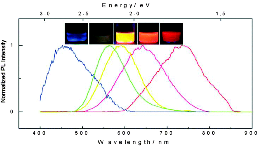 | ||
| Fig. 1 Photoluminescence spectra and corresponding fluorescence colors of SiQDs produced by controlled etching conditions. Reprinted with permission from Gupta et al.78 Copyright 2009 Wiley-VCH. | ||
Conventional QDs are usually made from semiconductor materials with a direct bandgap. The radiative transition pathway in SiQDs is different in character from that of conventional QDs because bulk silicon is an indirect bandgap semiconductor. In terms of the bio-applications of SiQDs, a detailed discussion of the SiQD electronic structure is beyond the scope of this review. However, it is worth mentioning that the exciton recombination rate is higher than that observed in bulk silicon because quantum confinement increases the uncertainty in k vector, meaning that previously unfavoured transitions are accessible. Veinot et al. suggest that,36 as well as confinement, surface effects may also be responsible for the observed rate of dipole-mediated radiative decay. Because it can be difficult to separate surface and confinement effects in free-standing colloidal nanocrystals, some work has been done to study this transition in systems where the SiQDs are embedded in a matrix.82
Similarly to conventional quantum dots, many preparations of SiQDs display decreased PL when transferred into aqueous solution. But the PL could be maintained by encapsulating SiQDs in phospholipid micelles.83 The origin of PL quenching of SiQDs upon transfer to aqueous media has been suggested to originate from the formation of non-radiative oxide-related states during surface treatments designed to render the SiQDs water soluble.84 Despite this, water-soluble SiQDs have been shown not to suffer from photobleaching under conditions which photobleached conventional organic dyes.80 Blinking of PL fluorescence is a commonly-observed phenomenon in fluorescent molecules including SiQDs.85 Galland et al. have suggested that the origin of blinking in semiconductor QDs is due to a combination of multiple effects; (i) non-radiative recombination caused by excess charges; and (ii) charge fluctuations in electron-accepting surface sites.86
Although SiQDs possess many of the desired physical properties for bio-applications, in order for them to be effective in practical contexts, the effect of preparation method and surface functionalization must be considered with respect to both photophysical features and biological interactions. These aspects will be reviewed in the following sections.
3. Methods of preparation
Numerous methods have been developed for preparing colloidal silicon quantum dots (SiQDs). Similar to the methods of preparing many types of nanostructures, these methods can be roughly classified as either ‘top-down’ approaches, i.e. breaking down large pieces of silicon to smaller nanoscale pieces, or ‘bottom-up’ approaches that primarily rely on self-assembly processes using molecular silicon precursor species. Due to the interdisciplinary nature of some methods, a third class of methods can be classified based on the involvement of both ‘top-down’ and ‘bottom-up’ components. Here, developments of methods for preparing colloidal SiQDs are summarized.3.1 The top-down approach
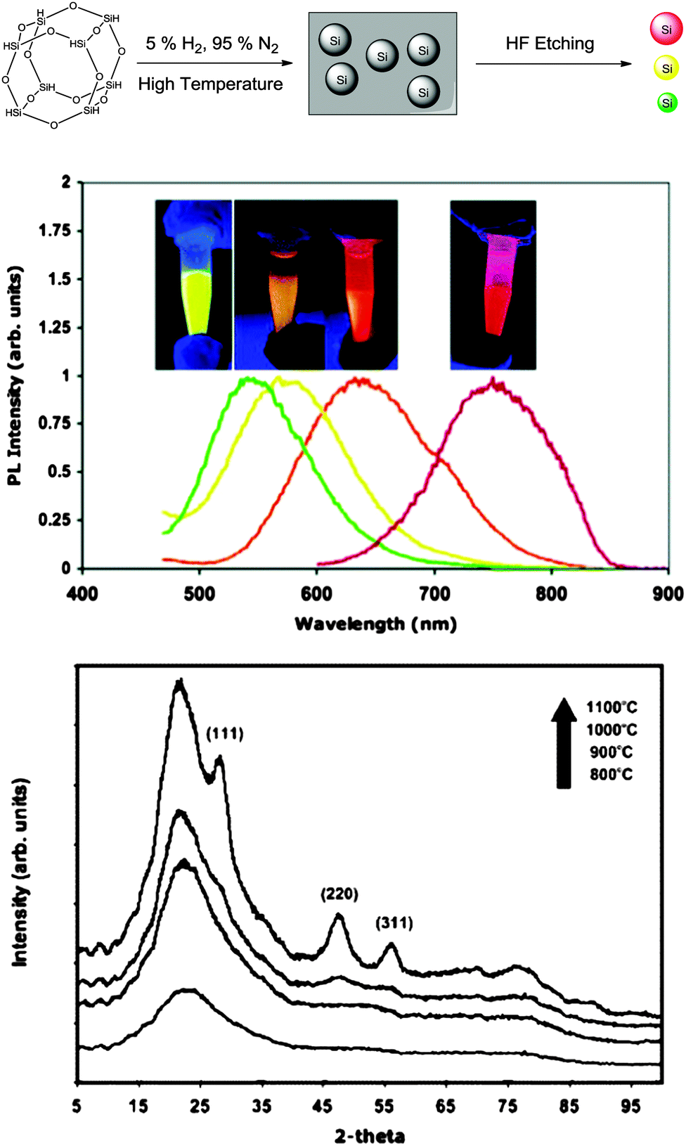
In addition, Kang et al. developed a variant of the etching method where the colour was tuneable from blue to red as determined by the size of the particles (Fig. 2).90 In this design, a graphite rod was used as the anode and silicon wafer as the cathode. One of the keys to this method was polyoxometalates where their unique ability to be an electron donor and acceptor simultaneously was exploited.90 Altering the current density was used to adjust the size of particles upon HF/H2O2 etching, producing shape and size controlled hydrogen terminated silicon nanoparticles with size ranging from 1–4 nm and emission peak between 450–700 nm.90 The etching mixture was further modified to provide control over the oxidizing environment using a mixture of H2O2 and ethanol,91 such that the larger particles (3 nm) were partially oxidized to yield small crystalline silicon cores in an oxide shell. As a result, oxide coated silicon nanocrystals of 1–3 nm with a wide spectrum of colours were obtained.91 Although it has been reported elsewhere that simple sonication of porous silicon without etching sometimes yield photoluminescent particles,92–94 it is important to realize that these micrometre sized particles contain domains of silicon nanoparticles in them, rather than colloidal silicon quantum dots which is the focus of this review.
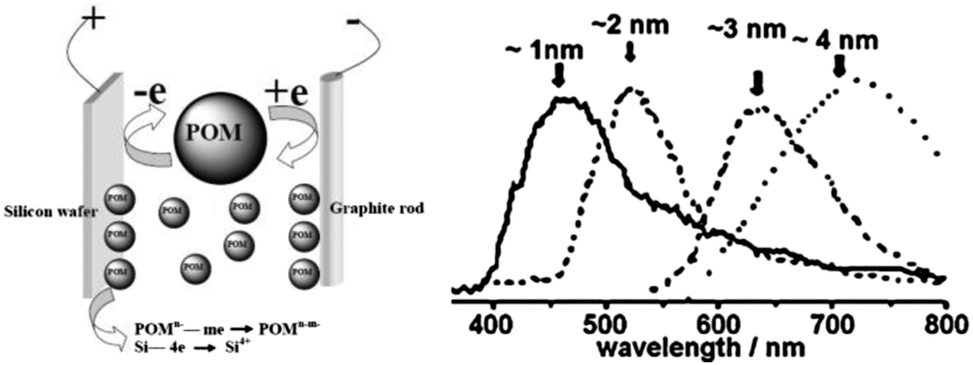 | ||
| Fig. 2 Polyoxometalates assisted electrochemical etching process of preparing colloidal SiNCs. Reprinted with permission from Kang et al.90 Copyright 2007 American Chemical Society. | ||
 | ||
| Fig. 3 Preparation of colloidal silicon nanocrystals by breaking down silicon rich oxides containing nanoparticles within them. Reprinted with permission from Hessel et al.95 Copyright 2006 American Chemical Society. | ||
3.2 The bottom-up approach
The alternative to the top-down routes mentioned above to prepare colloidal silicon nanocrystals is via assembly of small molecular precursors. That is, via a bottom-up approach.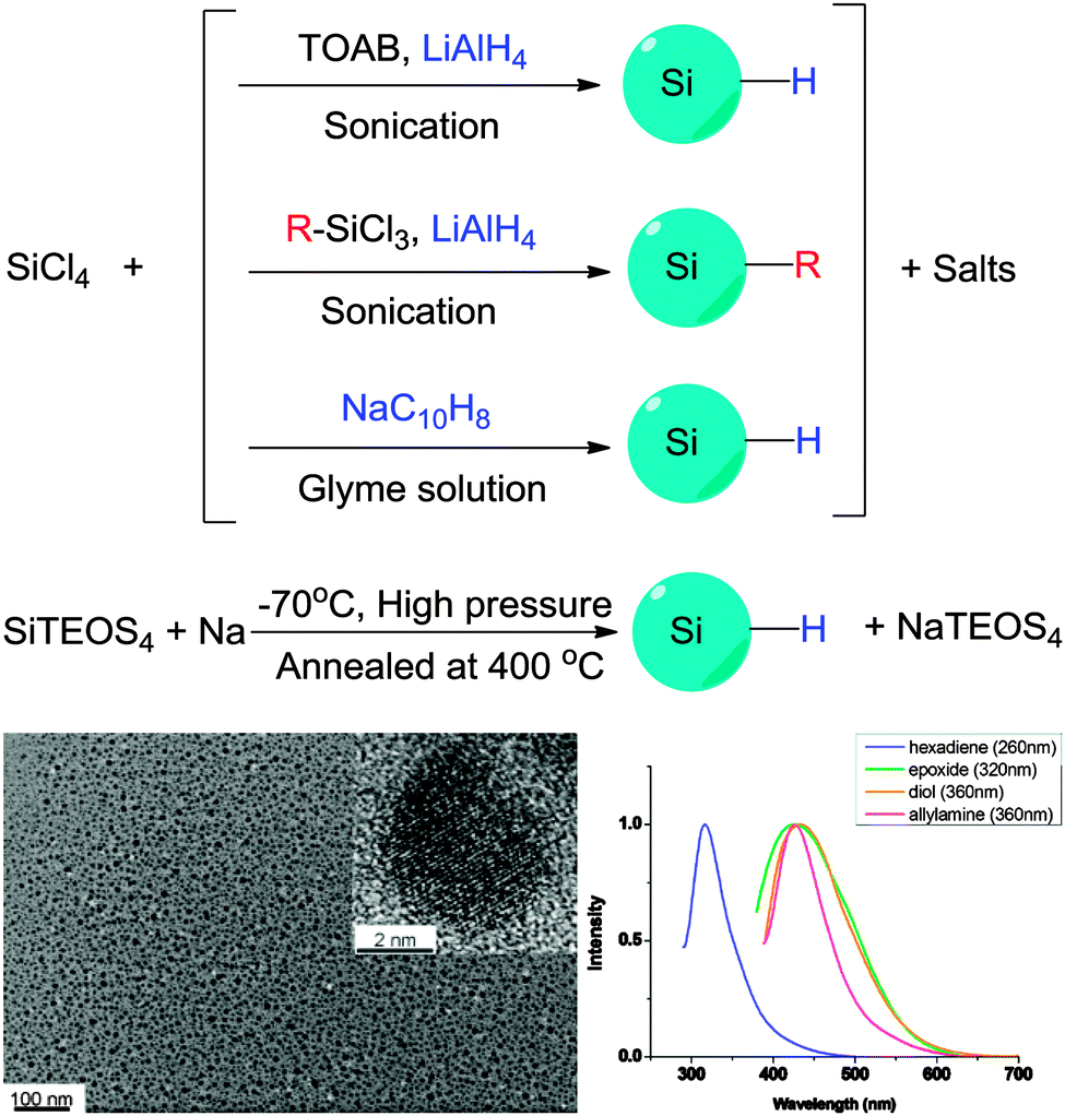 | ||
| Fig. 4 Preparation of colloidal silicon nanocrystals via solution based precursor reduction. HR-Tem images confirm crystal structure of the particles obtained, with fluorescence in the UV-blue region under UV excitation. Reprinted with permission from Tilley et al.106,107 Copyright 2010 American Chemical Society. | ||
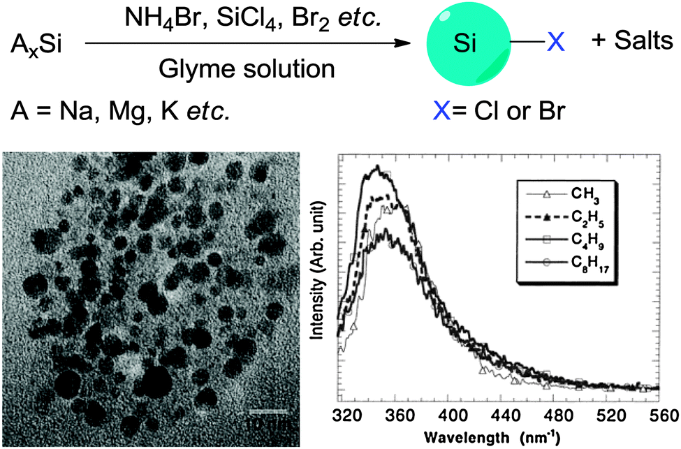 | ||
| Fig. 5 Zintl salts based synthetic methods of preparing SiNCs. Reprinted with permission from Yang et al.116 Copyright 1999 American Chemical Society. | ||
In contrast, an obvious problem with solution bottom-up methods is the lack of full spectrum of colour, with only blue-green colour accessible to date. Regardless the fact that red emitting dots can be made with laser pyrolysis and non-thermal plasma synthesis, variation of particle emission wavelength with the bottom-up approach has this far only been achieved by further etching the particles with concentrated HF, which is essentially a top-down approach. Also, although there are recent reports demonstrating that very high QY SiQDs can be synthesized by this class of method,35 particles prepared using bottom up approaches usually exhibited much lower quantum yield compared with top-down approaches, with quantum yield rarely exceeding 15%.
3.3 Precursor decomposition and re-assembly
A third class of methods typically involves the decomposition precursor species containing silicon heteroatoms and re-assembly processes to form SiQDs. Methods belonging to this class are distinct to previously discussed methods due to the multiple processes needed, which usually involve both the top-down and bottom-up steps.One disadvantage of methods belonging to this class is the use of specialized equipment. Temperature required for decomposing the precursor species is often very high, despite in some non-thermal plasma processes the actual operating temperature is close to room temperature. Highly toxic chemicals and procedures (i.e. HF etching) are often used, which requires strict control of every step in the preparation process due to the safety concerns.
4. Surface modifications
In contrast to the well-established methods of surface modification for II–IV semiconductor quantum dots,148 very different procedures are used for forming self-assembled monolayers (SAMs) on colloidal silicon quantum dots. Despite the use of silica shell for surface modification in some cases,149–151 probably the most common approach for introducing surface moieties to colloidal II–IV quantum dots is still via ligand exchange.152 Ligand exchange principle relies on replacing surfactant molecules with ligands with strong affinity with surface of quantum dots, using thiols,153–156 polymers,157–159 or certain inorganic ligands.160 However, comparable surface modification techniques for SiNCs typically require the formation of robust covalent linkages, usually between surface silicon atoms and carbon, nitrogen or oxygen species161 (Table 3). This is particularly important in preventing the oxidation of pristine silicon surfaces. Despite increasing interest in the surface passivation of SiQDs, complete characterization of the surface remains a challenge. The challenge is particularly evident when considering the incomplete coverage of organic monolayers on flat and porous silicon surfaces.161–166 In this section, we discuss recent methodological advances in surface modification of colloidal silicon quantum dots.| Surface of SiQDs | Surface modification strategies | Example of distal moieties |
|---|---|---|
|
|
Alkane |
| Alkene | ||
| NH2 | ||
| COOH | ||

|
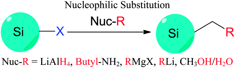
|
Hydrogen |
| Alkane | ||
| –OH |
4.1 Wet-chemical based modification strategies
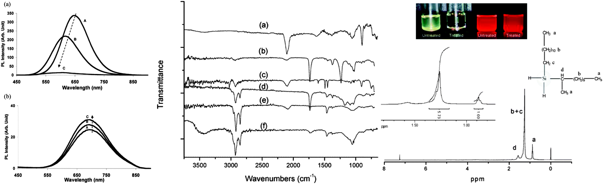 | ||
| Fig. 6 Attachment of different surface moieties to SiNCs via hydrosilylation. The reaction is initiated by photo-, thermal or catalytical treatment. Left: (a) unmodified silicon quantum dots showed instable photoluminescence. (A) immediate after preparation, (B) after 1 day, (C) after 12 days in toluene. (b) Grafted particles with improved PL stability. (A) immediately after preparation, (B) after 35 days, (C) after 60 days in toluene. Middle: FT-IR spectra of silicon quantum dots with a range of surface groups (a) hydrogen, (b) vinyl acetate, (c) styrene, (d) ethyl undecylenate, (e) 1-dodecene and (f) undecanol. Right: modified silicon quantum dots have improved dispersity in solvents and strong fluorescence (top). The surface groups were characterized by 1H-NMR spectroscopy (bottom). Reprinted with permission from Li et al. and Hua et al.38,104 Copyright 2004 & 2005 American Chemical Society. | ||
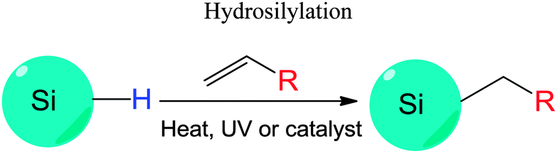
The Si–H bonds on nanocrystals then readily react with alkene or alkyne moieties to form robust Si–C bonds on silicon nanocrystals under thermal, photochemical, or in rarer cases catalytical treatment (Fig. 1).170 It was shown that both UV and near-UV irradiation allowed the attachment of alkenes on SiNCs' surface,84,132,173 but the reaction rate was slower on larger particles using near-UV light of 365 nm.84,173 Thermal methods have been equally successful with the hydrosilylation processes, with heating at 140 °C for 20 hours shown to attach alkenes on hydrogen terminated silicon quantum dots.103 In addition, common catalyst for hydrosilylation reaction, such as chloroplatinic acid (H2PtCl6) was used to initiate the reaction,107 though at a rate slower than thermal or photochemical activation.170 In a recent report by Korgel et al., it was shown that the process could occur even at room temperature with certain biofunctional alkenes, arguably because of the carboxylic acid facilitated nucleophilic attack on the curved surface.174 Due to the wide choices of the distal moieties of the surface molecules, it has been demonstrated that hydrosilylation allowed direct coupling of various polar (i.e. –NH2, –COOH, –SO32−) or non-polar (i.e. alkyl, alkenyl) moieties to the surface of silicon nanocrystals.115,175–177
Understanding the details of the mechanism of hydrosilylation is still the focus of intense studies and debates on bulk silicon surfaces, and much less work has been done with silicon quantum dots than bulk silicon. However, increasing evidence suggested that hydrosilylation on silicon nanocrystals happened in a comparable manner to flat or porous silicon84,167,173 (Fig. 7). Recently, it was depicted that hydrosilylation occurred via either a free radical or exciton mediated mechanism on particle surface.84,173 In the free radical initiated process (Fig. 7a), a hydride homolysis step due to thermal or photochemical treatment leads to the generation of free radicals, which allow the addition of alkene moiety in a chain of propagation process. In the exciton activated mechanism (Fig. 7b), no radical is generated, but photochemical generated excitions allow directly addition of nearby alkene moieties with the Si–H bonds, a comparable process to what happens on bulk silicon (Fig. 7c).84,173
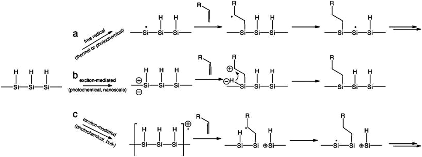 | ||
| Fig. 7 Proposed mechanism of hydrosilylation on silicon nanocrystals as a free radical (a) or exciton (b) initiated processes, in comparison with exciton mediated hydrosilylation on bulk silicon (c). Reprinted with permission from Kelly et al.,173 Copyright 2011 American Chemical Society. | ||
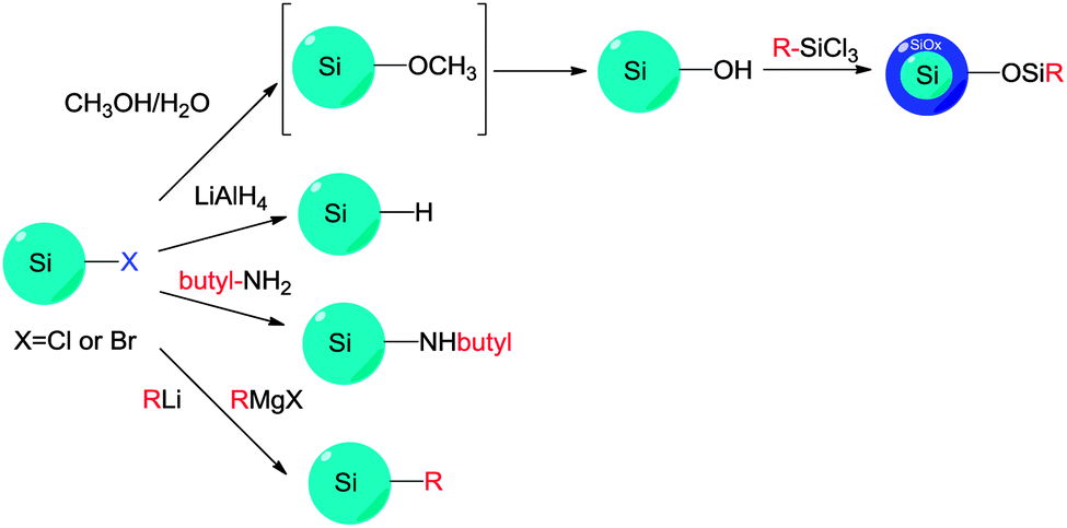 | ||
| Fig. 8 Modification of chloride-terminated silicon nanocrystals. The electrophilic reactivity and versatility of the Si–X moieties are used to introduce various surface groups. | ||
4.2 Surface passivation by plasma-surface interactions
In view of the above mentioned issues, and to explore new routes of surface modification for colloidal silicon nanocrystals, plasma assisted passivation has emerged as an alternative route to the wet-chemical approach. Based on the state of the plasma environment used, here we classify these methods into either aerosol, or liquid-phase plasma methods, respectively.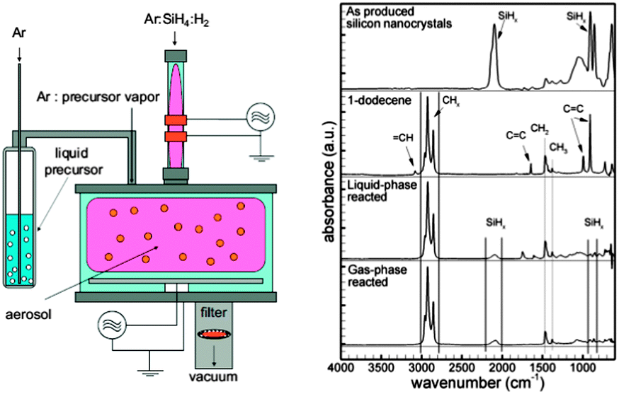 | ||
| Fig. 9 Typical experimental set-up for aerosol plasma functionalization of silicon nanocrystals (left). Silicon nanocrystals functionalized by this method showed similar FT-IR features compared with liquid-phase methods. Reprinted with permission from Mangolini et al.141 Copyright 2007 Wiley-VCH. | ||
Although surface engineering on silicon nanocrystals using plasma in the liquid phase is a relatively new concept, the available data still gave some mechanistic insights into how the modification reaction occurs. It was argued that using direct current to generate the plasma may externally ‘inject’ electrons in the liquid phase, which induces a cascade of radical events on the particle surface, allowing the addition of organic molecules.188 There has been no report so far showing the exact mechanism of how ultra-high frequency microplasma initiated any subsequent chemical reactions, but comparable characterization data of particle surface chemistry suggests a dominant role of plasma-electron interactions at the particle surface.188
4.3 Multi-step surface modifications
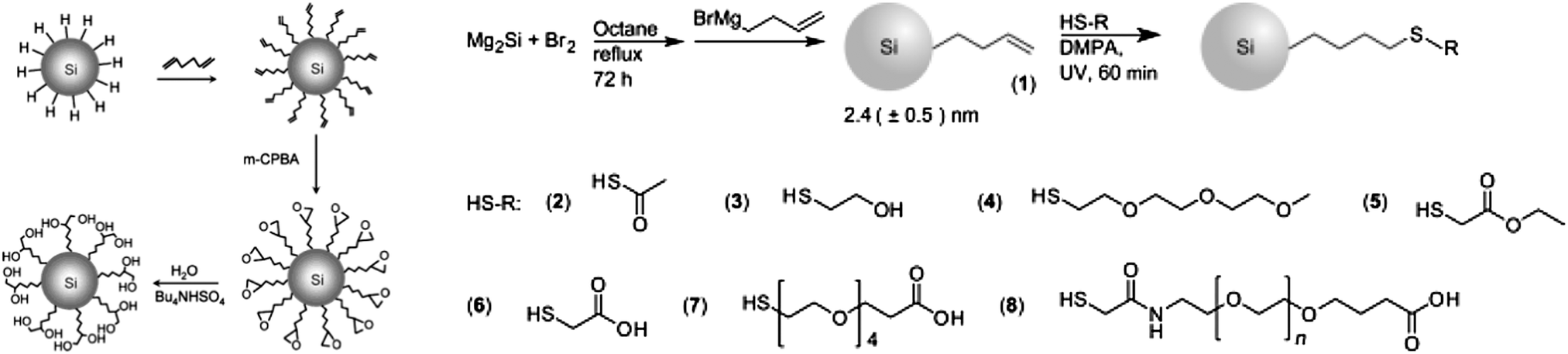
There is increasing interests in further engineering of the SAM architecture after the initial modification process. Two issues are identified for single stepped surface passivations: first, when the desired surface molecules have more than one functional group, it is more favoured to use a multi-step approach than a single-step strategy, so that competition of reactions between the reactive moieties can be minimized. Second, some surface molecules are hard to synthesize and often obtained in small quantity, it is therefore easier to attach these molecules onto the first SAM, rather than directly coupling with surface silicon species. In practice, the most challenging aspect of surface passivation is often how to preserve optical properties of the particles and introduce surface functionalities at the same time. This problem can be better addressed with a multi-step process. An early example of direct modification on the first SAM layer was shown by Kauzlarich et al., who demonstrated successful synthesis of siloxane coated particles via an intermediate hydroxyl terminated step.120Recently, Shiohara et al. reported a reaction chain by first modifying hydrogen terminated particles with hexadiene molecule,107 then further utilized the distal alkene group to produce epoxy, then diol functionalized particles (Fig. 10).107 In addition, Ruizendaal et al. and Cheng et al. used thiol–ene ‘click’ approach of functionalization, first prepared alkene-passivated silicon quantum dots, then further reacted the terminal alkene moieties with thiol molecules with a number of distal groups (Fig. 10).115,177 Due to the broad choices of commercially available thiols, this has allowed the production of colloidal silicon nanocrystals with a range of choice of surface functionalities.
 | ||
| Fig. 10 Several multiple-step modification strategies. Both methods shown here rely on the preparation of alkene-functionalized particles. Reprinted with permission from Shiohara et al.107 (left) and Ruizendaal et al.177 (right). Copyright 2010 American Chemical Society. Copyright 2011 Wiley-VCH. | ||
4.4 Characterizing the surface
When characterizing the surface chemistry of colloidal silicon quantum dots, two questions are of immediate concerns. The first concern is what molecular species are actually present on the surface. It was shown that a combination of NMR, IR and XPS studies can generally give a picture of the molecular species present. The second concern is the degree of surface coverage of the SAM. It was reported that surface coverage of the organic monolayer was from ∼55% on average to ∼80% at best for flat silicon (1 0 0) and silicon (1 1 1) surface,161 respectively. Porous silicon showed similar degree of coverage with highest reported value being 60%.164 However, studies on the level of monolayer coverage for silicon quantum dots are still rare, though several reports are present across the literature. One study by Hua et al. used XPS integrated peak area to indicate approximately 50% of monolayer coverage for 1.5 nm nanocrystals in plasma assisted modification of particle surface.132 Interestingly, the Si 2p peak measured in this work was at 102 eV, a position usually corresponding to oxides of bulk silicon, regardless both XRD and HR-TEM studies confirmed crystalline structure of the particles measured. Another study for estimating the level of surface coverage was reported by Swihart et al., who used thermo-gravimetric analysis (TGA) and 1H-NMR with an internal standard to show almost complete coverage of surface silicon atoms by photo-initiated hydrosilylation.132 However, to date no single method has been widely adopted to determine surface coverage rate for silicon nanoparticles, arguably due to the difficulty in accurate size measurement and complication of the actual surface chemistry, which could be different to what was observed for flat silicon surfaces.4.5 Impacts of surface chemistry on properties and theoretical studies
The surface chemistry for II–IV quantum dots and porous silicon has been well explored, and its importance for these nano-structured materials widely appreciated. Therefore it is unsurprising to recognize the critical role of surface chemistry for the understanding and applications of silicon nanocrystals, discussed in this section.First, control of surface chemistry allows control over the dispersity of particles in different solvents. As many solution based methods employed dry organic solvents, products obtained often were often Si–H terminated, a moiety prone to oxidation and incompatible with hydrophilic solvents. Extra surface modifications steps are required to enable particles to be dispersible within the solvent of choice, including water. Second, due to the small size of silicon nanocrystals, and hence large proportion of surface atoms, surface states plays a pivotal role in the optoelectronic properties of silicon nanocrystals, as discussed in Section 2.2. Despite the enormous efforts dedicated to methods of preparing and surface modifying silicon nanocrystals, much fewer studies have been focused on the relationship between the optical response and surface chemistries.42,189–192 There has been general agreement that quantum confinement, or particle size in this context, is a critical factor affecting wavelength of emission for all quantum dots. Surprisingly, silicon nanocrystals fabricated via etching methods usually emit in the red end of the visible spectrum,38,167 whereas those prepared by solution reduction methods often emitted blue or green colour which appeared to be independent of particle size.106,120,170 A recent study showed that a possible origin of the blue luminescence from silicon nanocrystals was related to the surface effect, especially due to the presence of nitrogen species on the surface.42 Although different colours can be achieved by size separation,76 in a joint study by the Kauzlarich, Tilley and Veinot group42 (Fig. 11), it was shown that mixing hydrogen terminated silicon quantum dots with nitrogen containing species in the presence of oxygen induces generation of the blue peak, with increased peak height with prolonged exposure level. Last but not least, introduction of bio-active moieties allows specific binding of the particle surface with the target molecules. As an essential attribute for any fluorescence imaging agent, specific interaction of the luminescent label with biological entity of interests (i.e. DNA, proteins etc.) is of paramount importance for studies. More recently, it was shown that by engaging silicon with hard donor molecules, hypervalent interactions can provide both colloidal stability as well as doping SiQDs.193
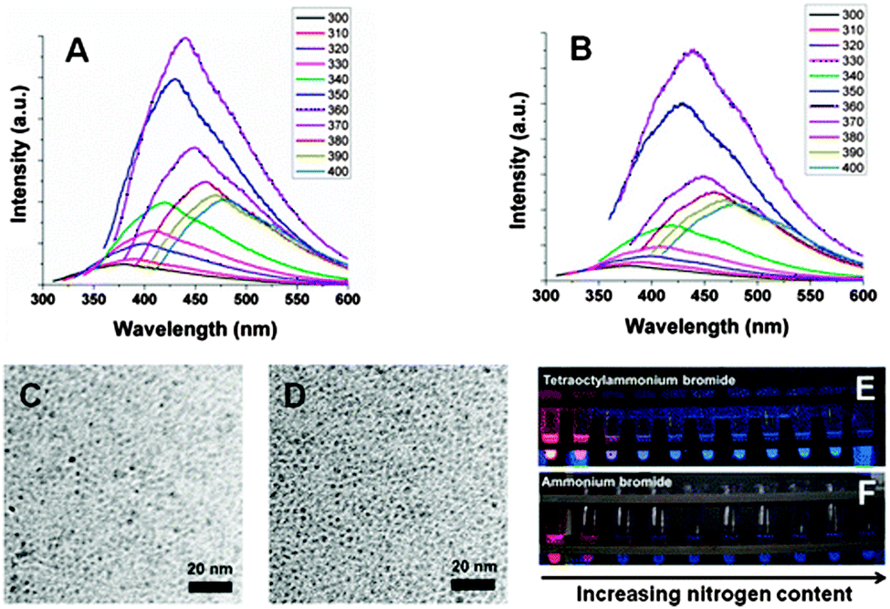 | ||
| Fig. 11 Increased nitrogen species on the surface of silicon nanocrystals induces blue luminescence. Reprinted with permission from Dasog et al.42 Copyright 2013 American Chemical Society. | ||
Due to the specific techniques used for successful grafting of surface molecules, theoretical calculation has emerged as a powerful method to assist with studying the impact of surface chemistry. An early study by Brus et al. suggested direct band gap transitions at blue emission of H terminated, ultrasmall (<2 nm) silicon quantum dots,194 which agreed with recent data obtained from many reduction methods.80,106,170 According to density function theory based calculations, it was shown that the alkyl group minimally changed the optical properties of silicon quantum dots compared with Si–H particles.195 Altering the amount of sulphur on the surface led to change of optical output.195 In addition, a recent reported suggested that hydrosilylation increased the emission intensity, but the carbon chain length did not significantly affect the absorption and emission wavelength (Fig. 12).189 Meanwhile, increasing surface coverage of the monolayer molecules only caused slight red-shift in the absorption spectrum, with little change in the emission profile.189 Further calculations suggested significant decrease of both excitation and emission energy of silicon nanocrystals, but removing the carbon coating may further improve the charge carrier properties of the nanoparticles.196 Among the various types of modifications, ab initio calculations suggested that introducing amine groups significantly alters emission behaviour of silicon nanocrystals for chloride coated particles,197 which had smaller bandgap compared with hydrogen terminated particles.198 Similarly, for fluorine passivated particles, surface effect became a more dominant factor to emission wavelength than quantum confinement for particles with size above 1.4 nm.190 Furthermore, for oxygen bonded silicon quantum dots, it was shown that the absorption energy was not heavily affected by the surface oxygen species, but emission wavelength red-shifted due to the presence of oxygen species on the surface.192
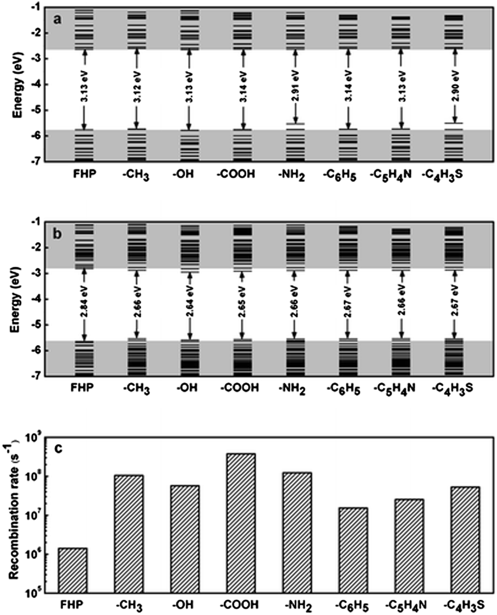 | ||
| Fig. 12 Energy level diagrams of silicon quantum dots with different distal moieties at (a) ground state and (b) excited state. (c) Radiative recombination rate. FHP: full hydrogen passivation. Reprinted with permission from Wang et al.189 Copyright 2012 American Chemical Society. | ||
5. Silicon quantum dots for bio-applications
5.1 Fluorescent imaging
The potential of colloidal quantum dots in fluorescent bio-imaging applications has been well recognized. Such application is particularly relevant to quantum dots that emit in the near infrared (NIR) region of 650 nm to 900 nm, due to the existence of tissue window in which light absorption and scattering is minimized. In spite of the numerous studies of fluorescence imaging using CdSe quantum dots, the first report involving SiQDs was not published until 2004 by Li and Ruckenstein.199 This work rapid attracted much attention, and a number of reports have been published ever since.83,106,121,200,201The most typical approach for bio-imaging using SiQDs is in vitro studies that show the uptake of particles by cell via endocytosis. For instance, Alsharif et al. reported the intracellular internalization of alkyl-functionalized SiQDs in human neoplastic and normal primary cells.202 It was found that cellular uptake rate was significantly faster for malignant cells in comparison with normal cells, and endocytosis was influenced by certain cholesterol derivatives.202 Tilley et al. reported cellular uptake of blue-luminescent, amine coated SiQDs, with no acute cellular toxicity observed.80,106 He et al. used SiQDs embedded in oxide to form nanoparticle spheres, demonstrated several endocytosis processes.37,201 Importantly, SiQDs in these studies were not functionalized with any bio-functional moieties to target the particles to any specific locations in the cell. Hence, particles simply are located throughout the cell and therefore further modification of the particles to ensure targeted interactions are required for practical considerations.
Phospholipid-encapsulated systems have shown promise in bio-imaging applications of fluorescent nanoparticles. The advantages of using phospholipids include the good colloidal stability and low non-specific adsorption.22 Erogbogbo et al. first demonstrated this process for SiQDs using hydrophobic SiQDs encapsulated in phospholipids to form micelle-type structures83 (Fig. 13). The particle–micelle system exhibited reasonable quantum yield (2%) and biocompatibility, as demonstrated by in vitro imaging studies with HeLa cells.83 A major benefit of this technique is that it offers a range of engineering choices on the micelle shell. For example, it was shown that modifying the phospholipid layer with 1,4,7,10-tetraazacyclododecane-1,4,7,10-tetraacetic acid (DOTA) ligands allowed the chelation of paramagnetic Gd ion.203 Alternatively, coupling the micelle layer with a dye donor allowed fluorescent resonance energy transfer (FRET) to happen,204 improving the undesired situation of fluorescence loss after encapsulation.204
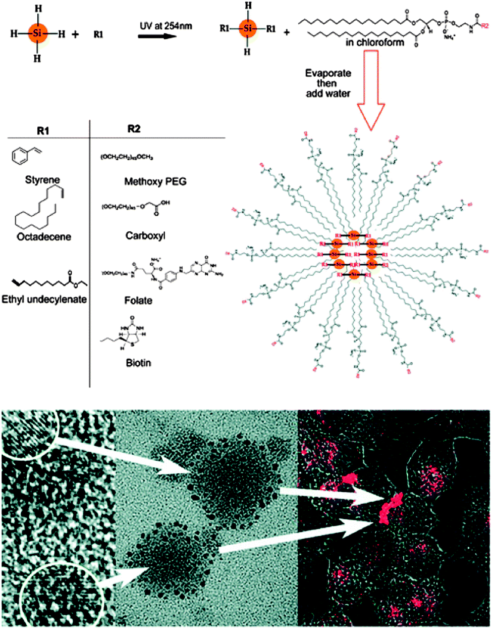 | ||
| Fig. 13 SiQDs encapsulated within phospholipid micelles. TEM images suggest SiQDs contained in phospholipids are several tens of nanometers in diameters in size. Uptake of the micelle is demonstrated by fluorescence imaging of Hela cells incubated with the particles. Reprinted with permission from Erogbogbo et al.83 Copyright 2008 American Chemical Society. | ||
One issue with fluorescent bio-imaging using SiQDs is the low excitation wavelength. The excitation wavelength for SiQDs is often in the UV-blue, a region that is outside of the tissue window (650–900 nm) so relevant to in vivo applications. One strategy to avoid the low wavelength excitation is using two photon techniques,206 where particles are excited by two photons of half the energy.206 It was shown that both excitation and emission can be achieved in the NIR wavelength.207 Another issue is sometimes the large hydrodynamic diameters (>10 nm) for phospholipid-coated dots that could potentially lead to slow degradation rate.208 Since most bio-imaging applications require the fluorescent label to be selectively attached with a biological entity, small particle radius, good colloidal stability and bio-active surfaces are equally important for bio-applicable silicon nanocrystals. It seems that these criteria can be best met with functionalization with self-assembled monolayers (SAMs).205,209 For instance, a recent report by Zhong et al. showed long term cellular imaging of cell nuclei for up to 60 min with no photobleaching (Fig. 14).205 Erogbogbo et al. showed selective uptake of colloidal SiQDs by cancer cells.209 That was achieved by covalently modifying the particles via EDC/NHS reaction with biomolecules including lysine, folate, antimesothelin and transferrin.209 After incubation with pancreatic cancer cells, folate and antimesothelin conjugated particles were selectively internalized by the cell.209
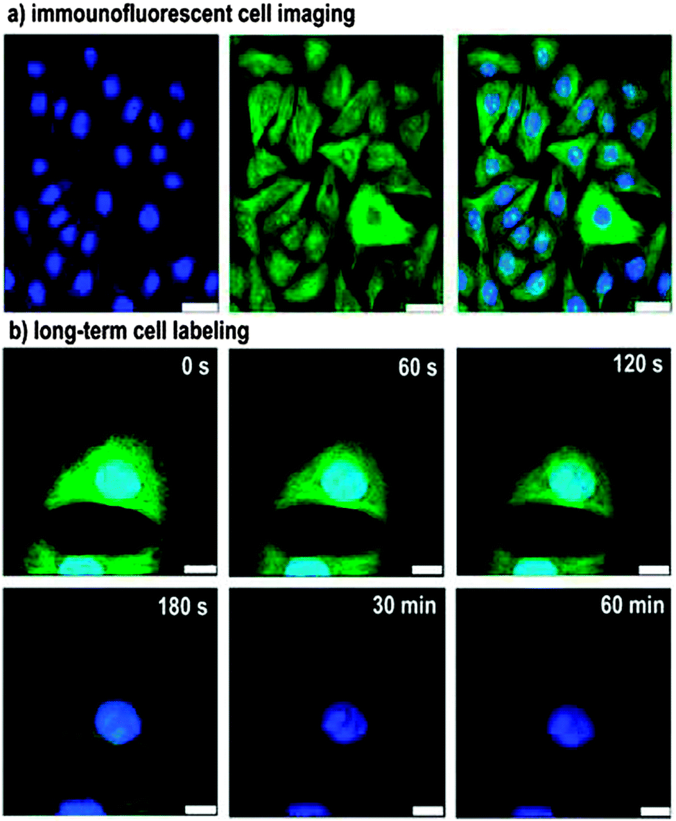 | ||
| Fig. 14 Immunofluorescent cell imaging by confocal microscopy. Illustrated as staining of microtubules by FITC (Green) and nucleus by silicon nanocrystals (blue), showing no photo-bleaching of SiNCs under one hour constant illumination. Reprinted with permission from Zhong et al.205 Copyright 2013 American Chemical Society. | ||
5.2 SiQDs for magnetic resonance imaging
An emerging field of using SiQDs in biomedical contexts is to explore their potential as MRI contrast agents. Although silicon by itself is not paramagnetic, paramagnetism can be achieved by adding paramagnetic species to the fluorescent dots to generate multimodalities.203,206,210 It was shown that when co-encapsulating SiQDs with paramagnetic Fe3O4 nanoparticles within phospholipids, the micelle exhibited both fluorescence and paramagnetism.210 Comparably, paramagnetism can be introduced by doping Mn directly to the particles,206 or with attachment of a Gd-chelate on particle surface,203 both resulted in prolonged T1 relaxation time that is desired for MRI applications. Although ‘doping’ is the term used here, direct evidence of alteration of the electronic structure is still lacking. The available data suggested most ‘doping’ attempts of SiQDs are more likely to be coordination of foreign species onto particle surface, rather than distortion of the lattice structure that was observed recently with cadmium or indium based dots.75,211–213 Furthermore, it was recently reported that larger silicon nanoparticles (d ∼ 350 nm) possess ultra-long 29Si magnetic hyperpolarization time which extends to tens of minutes in vivo.214,215 This is remarkable as an issue for the current MR active agents is the poor signal to noise ratio, which can be greatly improved by the state of hyperpolarization of 29Si via dynamic nuclear polarization (DNP).214,2155.3 Silicon quantum dots as a less toxic alternative to conventional quantum dots
One of the more attractive aspects of SiQDs for use in vivo is the low intrinsic toxicity of silicon as a material. During the past-decade, advances in synthetic and surface chemistry have allowed the preparation of monodisperse, photostable quantum dots (QDs) in aqueous solutions, inspiring the design of novel fluorescent labelling agents.20,23,148,216 However, the core materials of these quantum dots often contain heavy metal elements, such as cadmium (Cd). Due to the known toxicity of elemental Cd to biological systems, there have been intense debates over whether to use them in imaging contexts.217,218 Although the toxicity issue of QDs has been extensively reviewed elsewhere,27 we still highlight some of the most critical aspects here due to the importance of this topic.Investigations into the toxicity of quantum dots began with studying in vitro effects. Those studies indicate that QDs associated cytotoxicity may be primarily caused by release of cadmium ions, or the generation of free radicals.219 On the one hand, the cadmium core may contribute to biological damage caused by the QDs. One of the first systematic investigations was performed by Derfus and coworkers, who reported DNA/cell damage employing CdSe quantum dots with a variety of coating ligands.25 In particular, it was shown that CdSe QDs release cadmium ions after UV exposure, leading to cell and DNA damage.25 This result was supported by several other reports, suggesting the cytotoxic effects may be reduced to some extent by the coating with different surface ligands, such as mercaptoacetic acid (MAA), bovine serum albumin (BSA), mercaptoundecanoic acid (MUA), cysteamine (QD-NH2) or thioglycerol (QD-OH), mercaptopropionic acid (MPA) and polyethylene glycol (PEG).27,31 However, cytotoxicity cannot be completely eliminated as cell/DNA damage was observed after long term exposure to high concentration of surface coated QDs.25,27,31 On the other hand, another series of in-depth studies showed the generation of reactive oxygen intermediates (ROI) under UV may also contribute to the QDs toxicity. Inspired by the work of Green and Howman, who demonstrated DNA nicking takes place immediately upon the addition of QDs in dark conditions,220 electron paramagnetic resonance (EPR) studies suggested the formation of superoxide radicals from CdS dots, and hydroxyl radials from CdSe dots respectively.221 Based on their results, Ipe et al. concluded that although type and amount of radicals differ from each dot, ROI is indeed produced by QDs.221
Concerns about the toxicity of ‘conventional’ QDs steered researchers towards finding cadmium-free alternatives, and in recent years a plethora of candidates have been brought to light. Indium-based QDs including InP and InP/ZnS QDs have been reported, with the latter being demonstrated for pancreatic cancer imaging.222,223 Alternatively, CuInS2–ZnS core–shell QDs have been demonstrated for sentinel lymph node imaging in both visible and near-IR region.224–226 Zinc compounds that are often used as the shell material in conventional QDs have been put forward as a cadmium-free core material. By doping zinc-based QDs with heavy metal ions, strong emission in the visible region has been achieved.227 ZnS:Mn/ZnS core-doped core–shell QDs were used in vivo for tumour imaging,228 and recently Maity et al. compared the performance of three doped QD materials (Mn doped ZnS, Mn doped ZnSe and Cu doped InZnS) in vitro.229
Silicon is an attractive material for the preparation of cadmium free QDs because it is non-toxic in its bulk form and is readily degraded to silicic acid, which can be excreted in the urine.230 Silicon has even been suggested as a trace nutrient or food additive.231,232 Recently, a number of studies have demonstrated the low in vitro toxicity of SiQDs.202,233,234 With respect to in vivo studies, silicon's benign nature has inspired applications in tumour vasculature targeting, sentinel lymph node mapping and multicolour imaging in mice.208 It was shown that phospholipid encapsulated silicon quantum dots showed minimal in vivo toxicity at particle concentration up to ∼380 mg kg−1, a much higher value compared with studies performed with CdSe/ZnS quantum dots.208,235 Recently, Liu et al. performed in vivo toxicity studies of SiQDs in mice and monkeys and found no overt signs of toxicity at dose of 200 mg kg−1.133 However SiQDs did not seem to degrade as expected, although histological tests did not indicate any toxicity in monkey (Fig. 15).133 Positron emission tomography (PET) analysis suggested that after injection, most SiQDs are rapidly excreted via renal filtration with the remainder accumulating in the liver for weeks with no acute toxicity observed, regardless a level of inflammation response was observed.133,236 With all nanoparticle toxicity studies it is important to note that capping ligands, targeting moieties, nanoparticle shape, size and surface chemistry can all elicit a cellular response.237 For example, it was suggested that the surface chemistry of semiconductor QDs may significantly alter the potential for aggregation, and control of interface architecture have a significant impact on particle clearance from the body.238 Hence it is vital to perform a full toxicological characterization of the nanomaterial system as it will be used in the clinic in order to elicit a full picture of the organism's response.
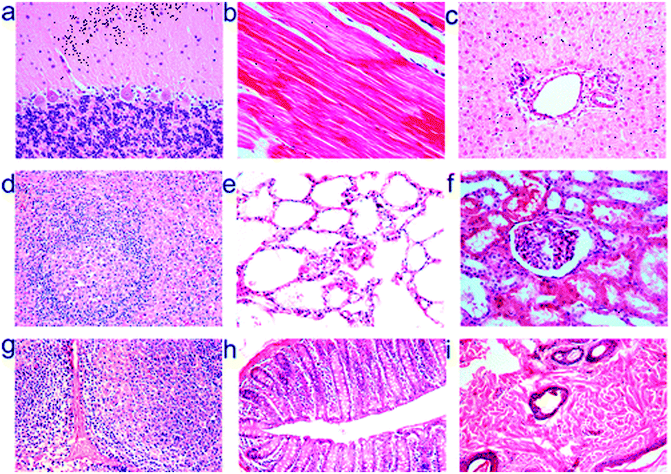 | ||
| Fig. 15 Histological images of rhesus macaques indicate no toxicity of silicon nanoparticles after 3 months of injection at dose of 200 mg kg−1. Images shown were tissues sample obtained from (a) brain, (b) heart, (c) liver, (d) spleen, (e) lung, (f) kidney, (g) lymph, (h) intestine and (i) skin at 40 times magnification. Reprinted with permission from Liu et al.133 Copyright 2013 American Chemical Society. | ||
6. Summary and future perspectives
In this critical review, we aim to bring together the current most relevant knowledge on the preparation, surface modification and bio-applications of colloidal silicon nanocrystals. Even though some of the early reports on silicon quantum dots were published almost twenty years ago,33,108 acceleration of research in this area was not seen until the new millennium. This is largely due to the slow progress in methodologies in the above mentioned sections, especially with preparation methods. The past decade has seen significant progress in these areas. As discussed in Section 3, high quality colloidal silicon quantum dots can now be prepared by a variety of routes via breaking down large pieces of materials or assembly of small molecular precursors. Monodisperse particles can now be prepared with good quantum yield and with reasonable control on emission, even though specific expertise is often required for such outcomes. As discussed in Section 4, the reactive particle surface is readily modifiable with well-developed, bench-top silicon chemistry, represented by the extensive use of hydrosilylation, and reactivity of halogenated particle surface. These modification techniques expanded the possibilities of utilizing colloidal silicon nanocrystals in more technology relevant contexts, such as labelling agents and sensing devices, where control of optical properties and molecular recognitions play key roles. Further motivation for the use of SiQDs in vivo, as an alternative to conventional metal containing QDs is given in Section 5.Several factors to consider when working with colloidal silicon nanocrystals are: (i) Selection of preparation methods. This is particularly important when considering concentrated HF, or harsh pressure/temperature conditions were sometimes used when making the particles. Much differing to the thorough mechanistic understanding of growth kinetics of cadmium dots, there currently still lacks a feasible solution method with thorough control of size/shape and optical features for silicon quantum dots. (ii) Strategies of surface modifications. This is a mandatory step required after the initial preparation in most cases and impact of the surface states is significant to emission features. Surface modification is also essential for attaching bio-recognition moieties to the particles. Hence we predict that surface modification techniques of silicon quantum dots will draw more attentions in the future. (iii) Characterization. Although the small particle size sometimes offers convenience to simple characterization methods such as IR and solution NMR spectroscopy, characterization of the surface structures can be very problematic as modification of surface constructs progress. In practice more time can be expended on knowing what is on the surface than preparing the particles itself. It is therefore important to consolidate the tool sets of characterization. The combined toolkit of preparation, characterization and application of SiQDs is a burgeoning field which shows great promise towards the goal of routine fluorescence imaging in vivo.
Acknowledgements
The authors thank Australian Research Council and Australian Centre for Nanomedicine for financial support of this project.Notes and references
- U. Resch-Genger, M. Grabolle, S. Cavaliere-Jaricot, R. Nitschke and T. Nann, Nat. Methods, 2008, 5, 763–775 CrossRef CAS PubMed.
- L. Brus, J. Phys. Chem., 1986, 90, 2555–2560 CrossRef CAS.
- L. E. Brus, J. Chem. Phys., 1984, 80, 4403–4409 CrossRef CAS.
- X. Peng, L. Manna, W. Yang, J. Wickham, E. Scher, A. Kadavanich and A. P. Alivisatos, Nature, 2000, 404, 59–61 CrossRef CAS PubMed.
- A. P. Alivisatos, J. Phys. Chem., 1996, 100, 13226–13239 CrossRef CAS.
- Z. A. Peng and X. G. Peng, J. Am. Chem. Soc., 2001, 123, 183–184 CrossRef CAS PubMed.
- C. B. Murray, D. J. Norris and M. G. Bawendi, J. Am. Chem. Soc., 1993, 115, 8706–8715 CrossRef CAS.
- X. G. Peng, J. Wickham and A. P. Alivisatos, J. Am. Chem. Soc., 1998, 120, 5343–5344 CrossRef CAS.
- J. M. Garcia, G. MedeirosRibeiro, K. Schmidt, T. Ngo, J. L. Feng, A. Lorke, J. Kotthaus and P. M. Petroff, Appl. Phys. Lett., 1997, 71, 2014–2016 CrossRef CAS.
- J. Y. Marzin, J. M. Gerard, A. Izrael, D. Barrier and G. Bastard, Phys. Rev. Lett., 1994, 73, 716–719 CrossRef CAS PubMed.
- F. W. Wise, Acc. Chem. Res., 2000, 33, 773–780 CrossRef CAS PubMed.
- D. V. Talapin, A. L. Rogach, E. V. Shevchenko, A. Kornowski, M. Haase and H. Weller, J. Am. Chem. Soc., 2002, 124, 5782–5790 CrossRef CAS PubMed.
- R. J. Ellingson, M. C. Beard, J. C. Johnson, P. R. Yu, O. I. Micic, A. J. Nozik, A. Shabaev and A. L. Efros, Nano Lett., 2005, 5, 865–871 CrossRef CAS PubMed.
- I. Robel, V. Subramanian, M. Kuno and P. V. Kamat, J. Am. Chem. Soc., 2006, 128, 2385–2393 CrossRef CAS PubMed.
- P. V. Kamat, J. Phys. Chem. C, 2008, 112, 18737–18753 CAS.
- G. Conibeer, M. Green, E.-C. Cho, D. König, Y.-H. Cho, T. Fangsuwannarak, G. Scardera, E. Pink, Y. Huang, T. Puzzer, S. Huang, D. Song, C. Flynn, S. Park, X. Hao and D. Mansfield, Thin Solid Films, 2008, 516, 6748–6756 CrossRef CAS.
- D. L. Huffaker, G. Park, Z. Zou, O. B. Shchekin and D. G. Deppe, Appl. Phys. Lett., 1998, 73, 2564–2566 CrossRef CAS.
- S. Strauf, K. Hennessy, M. T. Rakher, Y. S. Choi, A. Badolato, L. C. Andreani, E. L. Hu, P. M. Petroff and D. Bouwmeester, Phys. Rev. Lett., 2006, 96, 127404 CrossRef CAS PubMed.
- Q. Sun, Y. A. Wang, L. S. Li, D. Y. Wang, T. Zhu, J. Xu, C. H. Yang and Y. F. Li, Nat. Photonics, 2007, 1, 717–722 CrossRef CAS.
- X. Michalet, F. F. Pinaud, L. A. Bentolila, J. M. Tsay, S. Doose, J. J. Li, G. Sundaresan, A. M. Wu, S. S. Gambhir and S. Weiss, Science, 2005, 307, 538–544 CrossRef CAS PubMed.
- I. L. Medintz, H. T. Uyeda, E. R. Goldman and H. Mattoussi, Nat. Mater., 2005, 4, 435–446 CrossRef CAS PubMed.
- B. Dubertret, P. Skourides, D. J. Norris, V. Noireaux, A. H. Brivanlou and A. Libchaber, Science, 2002, 298, 1759–1762 CrossRef CAS PubMed.
- M. Bruchez, M. Moronne, P. Gin, S. Weiss and A. P. Alivisatos, Science, 1998, 281, 2013–2016 CrossRef CAS PubMed.
- W. C. W. Chan and S. Nie, Science, 1998, 281, 2016–2018 CrossRef CAS PubMed.
- A. M. Derfus, W. C. W. Chan and S. N. Bhatia, Nano Lett., 2004, 4, 11–18 CrossRef CAS.
- N. Lewinski, V. Colvin and R. Drezek, Small, 2008, 4, 26–49 CrossRef CAS PubMed.
- C. Kirchner, T. Liedl, S. Kudera, T. Pellegrino, A. M. Javier, H. E. Gaub, S. Stolzle, N. Fertig and W. J. Parak, Nano Lett., 2005, 5, 331–338 CrossRef CAS PubMed.
- G. Oberdorster, E. Oberdorster and J. Oberdorster, Environ. Health Perspect., 2005, 113, 823–839 CrossRef CAS PubMed.
- R. Hardman, Environ. Health Perspect., 2006, 114, 165–172 CrossRef PubMed.
- X. H. Gao, L. L. Yang, J. A. Petros, F. F. Marshal, J. W. Simons and S. M. Nie, Curr. Opin. Biotechnol., 2005, 16, 63–72 CrossRef CAS PubMed.
- A. Hoshino, K. Fujioka, T. Oku, M. Suga, Y. F. Sasaki, T. Ohta, M. Yasuhara, K. Suzuki and K. Yamamoto, Nano Lett., 2004, 4, 2163–2169 CrossRef CAS.
- W. L. Wilson, P. F. Szajowski and L. E. Brus, Science, 1993, 262, 1242–1244 CAS.
- B. Delley and E. F. Steigmeier, Phys. Rev. B: Condens. Matter Mater. Phys., 1993, 47, 1397–1400 CrossRef CAS.
- D. Jurbergs, E. Rogojina, L. Mangolini and U. Kortshagen, Appl. Phys. Lett., 2006, 88, 233116 CrossRef.
- Q. Li, Y. He, J. Chang, L. Wang, H. Chen, Y.-W. Tan, H. Wang and Z. Shao, J. Am. Chem. Soc., 2013, 135, 14924–14927 CrossRef CAS PubMed.
- J. G. Veinot, Chem. Commun., 2006, 4160–4168 RSC.
- Y. He, Z.-H. Kang, Q.-S. Li, C. H. A. Tsang, C.-H. Fan and S.-T. Lee, Angew. Chem., Int. Ed., 2009, 48, 128–132 CrossRef CAS PubMed.
- X. G. Li, Y. Q. He and M. T. Swihart, Langmuir, 2004, 20, 4720–4727 CrossRef CAS PubMed.
- L. Mangolini, E. Thimsen and U. Kortshagen, Nano Lett., 2005, 5, 655–659 CrossRef CAS PubMed.
- M. R. Linford and C. E. D. Chidsey, J. Am. Chem. Soc., 1993, 115, 12631–12632 CrossRef CAS.
- M. R. Linford, P. Fenter, P. M. Eisenberger and C. E. D. Chidsey, J. Am. Chem. Soc., 1995, 117, 3145–3155 CrossRef CAS.
- M. Dasog, Z. Yang, S. Regli, T. M. Atkins, A. Faramus, M. P. Singh, E. Muthuswamy, S. M. Kauzlarich, R. D. Tilley and J. G. C. Veinot, ACS Nano, 2013, 7, 2676–2685 CrossRef CAS PubMed.
- A. D. Yoffe, Adv. Phys., 1993, 42, 173–266 CrossRef CAS.
- M. Lannoo, C. Delerue, G. Allan and Y. M. Niquet, Philos. Trans. R. Soc., A, 2003, 361, 259–272 CrossRef CAS PubMed ; discussion 272–253.
- Y. Yin and A. P. Alivisatos, Nature, 2005, 437, 664–670 CrossRef CAS PubMed.
- H. S. Mansur, Wiley Interdiscip. Rev.: Nanomed. Nanobiotechnol., 2010, 2, 113–129 CrossRef CAS PubMed.
- G. D. Scholes and G. Rumbles, Nat. Mater., 2006, 5, 683–696 CrossRef CAS PubMed.
- I. L. Medintz, H. T. Uyeda, E. R. Goldman and H. Mattoussi, Nat. Mater., 2005, 4, 435–446 CrossRef CAS PubMed.
- H. Y. Liu, M. J. Steer, T. J. Badcock, D. J. Mowbray, M. S. Skolnick, P. Navaretti, K. M. Groom, M. Hopkinson and R. A. Hogg, Appl. Phys. Lett., 2005, 86, 143108 CrossRef.
- G. Allan, C. Delerue and M. Lannoo, Phys. Rev. Lett., 1996, 76, 2961–2964 CrossRef CAS PubMed.
- S. H. Tolbert, A. B. Herhold, C. S. Johnson and A. P. Alivisatos, Phys. Rev. Lett., 1994, 73, 3266–3269 CrossRef CAS PubMed.
- A. L. Efros, M. Rosen, M. Kuno, M. Nirmal, D. J. Norris and M. Bawendi, Phys. Rev. B: Condens. Matter Mater. Phys., 1996, 54, 4843–4856 CrossRef CAS.
- T. Trindade, P. O'Brien and N. L. Pickett, Chem. Mater., 2001, 13, 3843–3858 CrossRef CAS.
- A. D. Yoffe, Adv. Phys., 2001, 50, 1–208 CrossRef CAS.
- L. Landin, M. S. Miller, M. E. Pistol, C. E. Pryor and L. Samuelson, Science, 1998, 280, 262–264 CrossRef CAS PubMed.
- D. Bimberg, M. Grundmann, F. Heinrichsdorff, N. N. Ledentsov, V. M. Ustinov, A. E. Zhukov, A. R. Kovsh, M. V. Maximov, Y. M. Shernyakov, B. V. Volovik, A. F. Tsatsul'nikov, P. S. Kop'ev and Z. I. Alferov, Thin Solid Films, 2000, 367, 235–249 CrossRef CAS.
- R. B. Patel, A. J. Bennett, I. Farrer, C. A. Nicoll, D. A. Ritchie and A. J. Shields, Nat. Photonics, 2010, 4, 632–635 CrossRef CAS.
- J. V. Frangioni, Curr. Opin. Chem. Biol., 2003, 7, 626–634 CrossRef CAS PubMed.
- W. W. Yu, L. H. Qu, W. Z. Guo and X. G. Peng, Chem. Mater., 2004, 16, 560 CrossRef CAS.
- E. Kucur, F. M. Boldt, S. Cavaliere-Jaricot, J. Ziegler and T. Nann, Anal. Chem., 2007, 79, 8987–8993 CrossRef CAS PubMed.
- D. Rueda and N. G. Walter, Methods Mol. Biol., 2006, 335, 289–310 CAS.
- H. J. Gruber, C. D. Hahn, G. Kada, C. K. Riener, G. S. Harms, W. Ahrer, T. G. Dax and H. G. Knaus, Bioconjugate Chem., 2000, 11, 696–704 CrossRef CAS PubMed.
- S. A. Soper and Q. L. Mattingly, J. Am. Chem. Soc., 1994, 116, 3744–3752 CrossRef CAS.
- A. P. Alivisatos, W. Gu and C. Larabell, Annu. Rev. Biomed. Eng., 2005, 7, 55–76 CrossRef CAS PubMed.
- X. Y. Wang, L. H. Qu, J. Y. Zhang, X. G. Peng and M. Xiao, Nano Lett., 2003, 3, 1103–1106 CrossRef CAS.
- D. V. Talapin, I. Mekis, S. Gotzinger, A. Kornowski, O. Benson and H. Weller, J. Phys. Chem. B, 2004, 108, 18826–18831 CrossRef CAS.
- L. Spanhel, M. Haase, H. Weller and A. Henglein, J. Am. Chem. Soc., 1987, 109, 5649–5655 CrossRef CAS.
- S. Xu, S. Kumar and T. Nann, J. Am. Chem. Soc., 2006, 128, 1054–1055 CrossRef CAS PubMed.
- S. H. Mihindukulasuriya, T. K. Morcone and L. B. McGown, Electrophoresis, 2003, 24, 20–25 CrossRef CAS PubMed.
- M. Dahan, T. Laurence, F. Pinaud, D. S. Chemla, A. P. Alivisatos, M. Sauer and S. Weiss, Opt. Lett., 2001, 26, 825–827 CrossRef CAS PubMed.
- S. Takeoka, M. Fujii and S. Hayashi, Phys. Rev. B: Condens. Matter Mater. Phys., 2000, 62, 16820–16825 CrossRef CAS.
- X. M. Zhang, D. Neiner, S. Z. Wang, A. Y. Louie and S. M. Kauzlarich, Nanotechnology, 2007, 18, 095601 CrossRef PubMed.
- H. Sugimoto, M. Fujii, K. Imakita, S. Hayashi and K. Akamatsu, J. Phys. Chem. C, 2013, 117, 6807–6813 CAS.
- D. J. Norris, A. L. Efros and S. C. Erwin, Science, 2008, 319, 1776–1779 CrossRef CAS PubMed.
- D. Mocatta, G. Cohen, J. Schattner, O. Millo, E. Rabani and U. Banin, Science, 2011, 332, 77–81 CrossRef CAS PubMed.
- M. L. Mastronardi, F. Maier-Flaig, D. Faulkner, E. J. Henderson, C. Kübel, U. Lemmer and G. A. Ozin, Nano Lett., 2011, 12, 337–342 CrossRef PubMed.
- O. Wolf, M. Dasog, Z. Yang, I. Balberg, J. G. C. Veinot and O. Millo, Nano Lett., 2013, 13, 2738–2742 CrossRef PubMed.
- A. Gupta, M. T. Swihart and H. Wiggers, Adv. Funct. Mater., 2009, 19, 696–703 CrossRef CAS.
- N. Shirahata, Phys. Chem. Chem. Phys., 2011, 13, 7284–7294 RSC.
- J. H. Warner, A. Hoshino, K. Yamamoto and R. D. Tilley, Angew. Chem., Int. Ed., 2005, 44, 4550–4554 CrossRef CAS PubMed.
- K. Dohnalova, A. N. Poddubny, A. A. Prokofiev, W. D. A. M. de Boer, C. P. Umesh, J. M. J. Paulusse, H. Zuilhof and T. Gregorkiewicz, Light: Sci. Appl., 2013, 2, e47 CrossRef.
- L. Ding, T. P. Chen, Y. Liu, C. Y. Ng and S. Fung, Phys. Rev. B: Condens. Matter Mater. Phys., 2005, 72, 125419 CrossRef.
- F. Erogbogbo, K. T. Yong, I. Roy, G. Xu, P. N. Prasad and M. T. Swihart, ACS Nano, 2008, 2, 873–878 CrossRef CAS PubMed.
- J. A. Kelly and J. G. C. Veinot, ACS Nano, 2010, 4, 4645–4656 CrossRef CAS PubMed.
- B. Bruhn, J. Valenta, F. Sangghaleh and J. Linnros, Nano Lett., 2011, 11, 5574–5580 CrossRef CAS PubMed.
- C. Galland, Y. Ghosh, A. Steinbruck, M. Sykora, J. A. Hollingsworth, V. I. Klimov and H. Htoon, Nature, 2011, 479, U203–U275 CrossRef PubMed.
- W. R. Cannon, S. C. Danforth, J. H. Flint, J. S. Haggerty and R. A. Marra, J. Am. Ceram. Soc., 1982, 65, 324–330 CrossRef CAS.
- O. M. Nayfeh, D. A. Antoniadis, K. Mantey and M. H. Nayfeh, Appl. Phys. Lett., 2009, 94, 043112 CrossRef.
- K. Sato, H. Tsuji, K. Hirakuri, N. Fukata and Y. Yamauchi, Chem. Commun., 2009, 3759–3761 RSC.
- Z. Kang, C. H. A. Tsang, Z. Zhang, M. Zhang, N.-b. Wong, J. A. Zapien, Y. Shan and S.-T. Lee, J. Am. Chem. Soc., 2007, 129, 5326–5327 CrossRef CAS PubMed.
- Z. Kang, Y. Liu, C. H. A. Tsang, D. D. D. Ma, X. Fan, N.-B. Wong and S.-T. Lee, Adv. Mater., 2009, 21, 661–664 CrossRef CAS.
- G. Belomoin, J. Therrien, A. Smith, S. Rao, R. Twesten, S. Chaieb, M. H. Nayfeh, L. Wagner and L. Mitas, Appl. Phys. Lett., 2002, 80, 841–843 CrossRef CAS.
- M. H. Nayfeh, O. Akcakir, G. Belomoin, N. Barry, J. Therrien and E. Gratton, Appl. Phys. Lett., 2000, 77, 4086–4088 CrossRef CAS.
- M. H. Nayfeh, N. Barry, J. Therrien, O. Akcakir, E. Gratton and G. Belomoin, Appl. Phys. Lett., 2001, 78, 1131–1133 CrossRef CAS.
- C. M. Hessel, E. J. Henderson and J. G. C. Veinot, Chem. Mater., 2006, 18, 6139–6146 CrossRef CAS.
- D. Nesheva, C. Raptis, A. Perakis, I. Bineva, Z. Aneva, Z. Levi, S. Alexandrova and H. Hofmeister, J. Appl. Phys., 2002, 92, 4678–4683 CrossRef CAS.
- B. Garrido, C. Garcia, S. Y. Seo, P. Pellegrino, D. Navarro-Urrios, N. Daldosso, L. Pavesi, F. Gourbilleau and R. Rizk, Phys. Rev. B: Condens. Matter Mater. Phys., 2007, 76, 245308 CrossRef.
- S.-M. Liu, Y. Yang, S. Sato and K. Kimura, Chem. Mater., 2006, 18, 637–642 CrossRef CAS.
- S.-m. Liu, S. Sato and K. Kimura, Langmuir, 2005, 21, 6324–6329 CrossRef CAS PubMed.
- C. M. Hessel, M. A. Summers, A. Meldrum, M. Malac and J. G. C. Veinot, Adv. Mater., 2007, 19, 3513–3516 CrossRef CAS.
- C. M. Hessel, D. Reid, M. G. Panthani, M. R. Rasch, B. W. Goodfellow, J. Wei, H. Fujii, V. Akhavan and B. A. Korgel, Chem. Mater., 2011, 24, 393–401 CrossRef.
- C. M. Hessel, E. J. Henderson and J. G. C. Veinot, J. Phys. Chem. C, 2007, 111, 6956–6961 CAS.
- J. A. Kelly, E. J. Henderson and J. G. Veinot, Chem. Commun., 2010, 46, 8704–8718 RSC.
- F. Hua, M. T. Swihart and E. Ruckenstein, Langmuir, 2005, 21, 6054–6062 CrossRef CAS PubMed.
- E. J. Henderson and J. G. C. Veinot, Chem. Mater., 2007, 19, 1886–1888 CrossRef CAS.
- R. D. Tilley and K. Yamamoto, Adv. Mater., 2006, 18, 2053–2056 CrossRef CAS.
- A. Shiohara, S. Hanada, S. Prabakar, K. Fujioka, T. H. Lim, K. Yamamoto, P. T. Northcote and R. D. Tilley, J. Am. Chem. Soc., 2010, 132, 248–253 CrossRef CAS PubMed.
- J. R. Heath, Science, 1992, 258, 1131–1133 CAS.
- R. K. Baldwin, K. A. Pettigrew, E. Ratai, M. P. Augustine and S. M. Kauzlarich, Chem. Commun., 2002, 1822–1823 RSC.
- N. Arul Dhas, C. P. Raj and A. Gedanken, Chem. Mater., 1998, 10, 3278–3281 CrossRef.
- J. P. Wilcoxon, G. A. Samara and P. N. Provencio, Phys. Rev. B: Condens. Matter Mater. Phys., 1999, 60, 2704–2714 CrossRef CAS.
- S. Prabakar, A. Shiohara, S. Hanada, K. Fujioka, K. Yamamoto and R. D. Tilley, Chem. Mater., 2010, 22, 482–486 CrossRef CAS.
- A. Shiohara, S. Prabakar, A. Faramus, C. Y. Hsu, P. S. Lai, P. T. Northcote and R. D. Tilley, Nanoscale, 2011, 3, 3364–3370 RSC.
- J. Wang, S. Sun, F. Peng, L. Cao and L. Sun, Chem. Commun., 2011, 47, 4941–4943 RSC.
- X. Y. Cheng, R. Gondosiswanto, S. Ciampi, P. J. Reece and J. J. Gooding, Chem. Commun., 2012, 48, 11874–11876 RSC.
- C. S. Yang, R. A. Bley, S. M. Kauzlarich, H. W. H. Lee and G. R. Delgado, J. Am. Chem. Soc., 1999, 121, 5191–5195 CrossRef CAS.
- D. Mayeri, B. L. Phillips, M. P. Augustine and S. M. Kauzlarich, Chem. Mater., 2001, 13, 765–770 CrossRef CAS.
- R. K. Baldwin, K. A. Pettigrew, J. C. Garno, P. P. Power, G. Y. Liu and S. M. Kauzlarich, J. Am. Chem. Soc., 2002, 124, 1150–1151 CrossRef CAS PubMed.
- R. A. Bley and S. M. Kauzlarich, J. Am. Chem. Soc., 1996, 118, 12461–12462 CrossRef CAS.
- J. Zou, R. K. Baldwin, K. A. Pettigrew and S. M. Kauzlarich, Nano Lett., 2004, 4, 1181–1186 CrossRef CAS.
- B. A. Manhat, A. L. Brown, L. A. Black, J. B. A. Ross, K. Fichter, T. Vu, E. Richman and A. M. Goforth, Chem. Mater., 2011, 23, 2407–2418 CrossRef CAS PubMed.
- C.-S. Yang, R. A. Bley, S. M. Kauzlarich, H. W. H. Lee and G. R. Delgado, J. Am. Chem. Soc., 1999, 121, 5191–5195 CrossRef CAS.
- J. D. Holmes, K. J. Ziegler, R. C. Doty, L. E. Pell, K. P. Johnston and B. A. Korgel, J. Am. Chem. Soc., 2001, 123, 3743–3748 CrossRef CAS PubMed.
- D. S. English, L. E. Pell, Z. H. Yu, P. F. Barbara and B. A. Korgel, Nano Lett., 2002, 2, 681–685 CrossRef CAS.
- Y. He, Y. L. Zhong, F. Peng, X. P. Wei, Y. Y. Su, Y. M. Lu, S. Su, W. Gu, L. S. Liao and S. T. Lee, J. Am. Chem. Soc., 2011, 133, 14192–14195 CrossRef CAS PubMed.
- W. R. Cannon, S. C. Danforth, J. S. Haggerty and R. A. Marra, J. Am. Ceram. Soc., 1982, 65, 330–335 CrossRef CAS.
- F. Huisken, B. Kohn and V. Paillard, Appl. Phys. Lett., 1999, 74, 3776–3778 CrossRef CAS.
- G. Ledoux, J. Gong and F. Huisken, Appl. Phys. Lett., 2001, 79, 4028–4030 CrossRef CAS.
- G. Ledoux, J. Gong, F. Huisken, O. Guillois and C. Reynaud, Appl. Phys. Lett., 2002, 80, 4834–4836 CrossRef CAS.
- K. Potrick, T. Schmidt, S. Bublitz, C. Muhlig, W. Paa and F. Huisken, Appl. Phys. Lett., 2011, 98, 083111 CrossRef.
- L. B. Ma, T. Schmidt, O. Guillois and F. Huisken, Appl. Phys. Lett., 2009, 95, 013115 CrossRef.
- F. J. Hua, M. T. Swihart and E. Ruckenstein, Langmuir, 2005, 21, 6054–6062 CrossRef CAS PubMed.
- J. Liu, F. Erogbogbo, K.-T. Yong, L. Ye, J. Liu, R. Hu, H. Chen, Y. Hu, Y. Yang, J. Yang, I. Roy, N. A. Karker, M. T. Swihart and P. N. Prasad, ACS Nano, 2013, 7, 7303–7310 CrossRef CAS PubMed.
- U. Kortshagen, J. Phys. D: Appl. Phys., 2009, 42, 113001 CrossRef.
- G. Viera, S. Huet, M. Mikikian and L. Boufendi, Thin Solid Films, 2002, 403, 467–470 CrossRef.
- G. Viera, M. Mikikian, E. Bertran, P. R. I. Cabarrocas and L. Boufendi, J. Appl. Phys., 2002, 92, 4684–4694 CrossRef CAS.
- M. Otobe, T. Kanai, T. Ifuku, H. Yajima and S. Oda, J. Non-Cryst. Solids, 1996, 198, 875–878 CrossRef.
- S. Oda, Adv. Colloid Interface Sci., 1997, 71–72, 31–47 CrossRef CAS.
- S. Oda and M. Otobe, in Microcrystalline and Nanocrystalline Semiconductors, ed. R. W. Collins, C. C. Tsai, M. Hirose, F. Koch and L. Brus, Materials Research Soc., Pittsburgh, 1995, vol. 358, pp. 721–731 Search PubMed.
- A. Bapat, M. Gatti, Y.-P. Ding, S. A. Campbell and U. Kortshagen, J. Phys. D: Appl. Phys., 2007, 40, 2247–2257 CrossRef CAS.
- L. Mangolini and U. Kortshagen, Adv. Mater., 2007, 19, 2513–2519 CrossRef CAS.
- L. Mangolini, E. Thimsen and U. Kortshagen, in Amorphous and Nanocrystalline Silicon Science and Technology-2005, ed. R. W. Collins, P. C. Taylor, M. Kondo, R. Carius and R. Biswas, 2005, vol. 862, pp. 307–312 Search PubMed.
- L. Mangolini, D. Jurbergs, E. Rogojina and U. Kortshagen, J. Lumin., 2006, 121, 327–334 CrossRef CAS.
- U. Kortshagen, L. Mangolini and A. Bapat, J. Nanopart. Res., 2007, 9, 39–52 CrossRef CAS.
- X. D. Pi, L. Mangolini, S. A. Campbell and U. Kortshagen, Phys. Rev. B: Condens. Matter Mater. Phys., 2007, 75, 085423 CrossRef.
- J. Knipping, H. Wiggers, B. Rellinghaus, P. Roth, D. Konjhodzic and C. Meier, J. Nanosci. Nanotechnol., 2004, 4, 1039–1044 CrossRef CAS PubMed.
- R. M. Sankaran, D. Holunga, R. C. Flagan and K. P. Giapis, Nano Lett., 2005, 5, 537–541 CrossRef CAS PubMed.
- I. L. Medintz, H. T. Uyeda, E. R. Goldman and H. Mattoussi, Nat. Mater., 2005, 4, 435–446 CrossRef CAS PubMed.
- D. Gerion, F. Pinaud, S. C. Williams, W. J. Parak, D. Zanchet, S. Weiss and A. P. Alivisatos, J. Phys. Chem. B, 2001, 105, 8861–8871 CrossRef CAS.
- A. Burns, H. Ow and U. Wiesner, Chem. Soc. Rev., 2006, 35, 1028–1042 RSC.
- P. Mulvaney, L. M. Liz-Marzan, M. Giersig and T. Ung, J. Mater. Chem., 2000, 10, 1259–1270 RSC.
- F. Dubois, B. Mahler, B. Dubertret, E. Doris and C. Mioskowski, J. Am. Chem. Soc., 2007, 129, 482–483 CrossRef CAS PubMed.
- S. F. Wuister, C. D. Donega and A. Meijerink, J. Phys. Chem. B, 2004, 108, 17393–17397 CrossRef CAS.
- N. Gaponik, D. V. Talapin, A. L. Rogach, K. Hoppe, E. V. Shevchenko, A. Kornowski, A. Eychmuller and H. Weller, J. Phys. Chem. B, 2002, 106, 7177–7185 CrossRef CAS.
- A. Shavel, N. Gaponik and A. Eychmuller, J. Phys. Chem. B, 2006, 110, 19280–19284 CrossRef CAS PubMed.
- A. Eychmuller and A. L. Rogach, Pure Appl. Chem., 2000, 72, 179–188 CrossRef CAS.
- C.-A. J. Lin, R. A. Sperling, J. K. Li, T.-Y. Yang, P.-Y. Li, M. Zanella, W. H. Chang and W. J. Parak, Small, 2008, 4, 334–341 CrossRef CAS PubMed.
- N. Tomczak, D. Janczewski, M. Y. Han and G. J. Vancso, Prog. Polym. Sci., 2009, 34, 393–430 CrossRef CAS.
- W. W. Yu, E. Chang, J. C. Falkner, J. Y. Zhang, A. M. Al-Somali, C. M. Sayes, J. Johns, R. Drezek and V. L. Colvin, J. Am. Chem. Soc., 2007, 129, 2871–2879 CrossRef CAS PubMed.
- J. Tang, K. W. Kemp, S. Hoogland, K. S. Jeong, H. Liu, L. Levina, M. Furukawa, X. H. Wang, R. Debnath, D. K. Cha, K. W. Chou, A. Fischer, A. Amassian, J. B. Asbury and E. H. Sargent, Nat. Mater., 2011, 10, 765–771 CrossRef CAS PubMed.
- S. Ciampi, J. B. Harper and J. J. Gooding, Chem. Soc. Rev., 2010, 39, 2158–2183 RSC.
- N. S. Bhairamadgi, S. Gangarapu, M. A. C. Campos, J. M. J. Paulusse, C. J. M. van Rijn and H. Zuilhof, Langmuir, 2013, 29, 4535–4542 CrossRef CAS PubMed.
- S. Ciampi, T. Bocking, K. A. Kilian, M. James, J. B. Harper and J. J. Gooding, Langmuir, 2007, 23, 9320–9329 CrossRef CAS PubMed.
- T. Bocking, K. A. Kilian, K. Gaus and J. J. Gooding, Adv. Funct. Mater., 2008, 18, 3827–3833 CrossRef CAS.
- E. J. Anglin, L. Y. Cheng, W. R. Freeman and M. J. Sailor, Adv. Drug Delivery Rev., 2008, 60, 1266–1277 CrossRef CAS PubMed.
- K. A. Kilian, T. Bocking, K. Gaus, M. Gal and J. J. Gooding, Biomaterials, 2007, 28, 3055–3062 CrossRef CAS PubMed.
- J. R. Rodríguez Núñez, J. A. Kelly, E. J. Henderson and J. G. C. Veinot, Chem. Mater., 2011, 24, 346–352 CrossRef.
- Z. H. Kang, C. H. A. Tsang, N. B. Wong, Z. D. Zhang and S. T. Lee, J. Am. Chem. Soc., 2007, 129, 12090–12091 CrossRef CAS PubMed.
- L. Mangolini, E. Thimsen and U. Kortshagen, Amorphous and Nanocrystalline Silicon Science and Technology-2005, 2005, vol. 862, pp. 307–312 Search PubMed.
- R. D. Tilley, J. H. Warner, K. Yamamoto, I. Matsui and H. Fujimori, Chem. Commun., 2005, 1833–1835 RSC.
- X. Li and P. W. Bohn, Appl. Phys. Lett., 2000, 77, 2572–2574 CrossRef CAS.
- C. M. Hessel, E. J. Henderson, J. A. Kelly, R. G. Cavell, T.-K. Sham and J. G. C. Veinot, J. Phys. Chem. C, 2008, 112, 14247–14254 CAS.
- J. A. Kelly, A. M. Shukaliak, M. D. Fleischauer and J. G. C. Veinot, J. Am. Chem. Soc., 2011, 133, 9564–9571 CrossRef CAS PubMed.
- Y. Yu, C. M. Hessel, T. D. Bogart, M. G. Panthani, M. R. Rasch and B. A. Korgel, Langmuir, 2013, 29, 1533–1540 CrossRef CAS PubMed.
- M. Rosso-Vasic, E. Spruijt, Z. Popovic, K. Overgaag, B. van Lagen, B. Grandidier, D. Vanmaekelbergh, D. Dominguez-Gutierrez, L. De Cola and H. Zuilhof, J. Mater. Chem., 2009, 19, 5926–5933 RSC.
- J. R. Siekierzycka, M. Rosso-Vasic, H. Zuilhof and A. M. Brouwer, J. Phys. Chem. C, 2011, 115, 20888–20895 CAS.
- L. Ruizendaal, S. P. Pujari, V. Gevaerts, J. M. Paulusse and H. Zuilhof, Chem.–Asian J., 2011, 6, 2776–2786 CrossRef CAS PubMed.
- E. Rogozhina, G. Belomoin, A. Smith, L. Abuhassan, N. Barry, O. Akcakir, P. V. Braun and M. H. Nayfeh, Appl. Phys. Lett., 2001, 78, 3711–3713 CrossRef CAS.
- Y.-C. Liao and J. T. Roberts, J. Am. Chem. Soc., 2006, 128, 9061–9065 CrossRef CAS PubMed.
- V. Svrcek, D. Mariotti and M. Kondo, Appl. Phys. Lett., 2010, 97, 161502 CrossRef.
- V. Svrcek, T. Yamanari, D. Mariotti, K. Matsubara and M. Kondo, Appl. Phys. Lett., 2012, 100, 223904 CrossRef.
- J. McKenna, J. Patel, S. Mitra, N. Soin, V. Svrcek, P. Maguire and D. Mariotti, Eur. Phys. J.: Appl. Phys., 2011, 56, 24020 CrossRef.
- D. Mariotti and R. M. Sankaran, J. Phys. D: Appl. Phys., 2010, 43, 323001 CrossRef.
- D. Mariotti and R. M. Sankaran, J. Phys. D: Appl. Phys., 2011, 44, 174023 CrossRef.
- D. Mariotti, J. Patel, V. Svrcek and P. Maguire, Plasma Processes Polym., 2012, 9, 1074–1085 CrossRef CAS.
- V. Svrcek, D. Mariotti, Y. Shibata and M. Kondo, J. Phys. D: Appl. Phys., 2010, 43, 415402 CrossRef.
- D. Mariotti, V. Svrcek, J. W. J. Hamilton, M. Schmidt and M. Kondo, Adv. Funct. Mater., 2012, 22, 954–964 CrossRef CAS.
- D. Mariotti, S. Mitra and V. Svrcek, Nanoscale, 2013, 5, 1385–1398 RSC.
- R. Wang, X. D. Pi and D. R. Yang, J. Phys. Chem. C, 2012, 116, 19434–19443 CAS.
- Y. Ma, X. Pi and D. Yang, J. Phys. Chem. C, 2012, 116, 5401–5406 CAS.
- M. J. Llansola Portolés, R. Pis Diez, M. L. Dell'Arciprete, P. Caregnato, J. J. Romero, D. O. Mártire, O. Azzaroni, M. Ceolín and M. C. Gonzalez, J. Phys. Chem. C, 2012, 116, 11315–11325 Search PubMed.
- X. Chen, X. Pi and D. Yang, J. Phys. Chem. C, 2010, 114, 8774–8781 CAS.
- L. M. Wheeler, N. R. Neale, T. Chen and U. R. Kortshagen, Nat. Commun., 2013, 4, 2197 Search PubMed.
- Z. Y. Zhou, L. Brus and R. Friesner, Nano Lett., 2003, 3, 163–167 CrossRef CAS.
- Q. S. Li, R. Q. Zhang, S. T. Lee, T. A. Niehaus and T. Frauenheim, J. Chem. Phys., 2008, 128, 244714 CrossRef CAS PubMed.
- Z. Y. Ni, X. D. Pi and D. R. Yang, RSC Adv., 2012, 2, 11227–11230 RSC.
- R. Wang, X. Pi and D. Yang, Phys. Chem. Chem. Phys., 2013, 15, 1815–1820 RSC.
- A. Carvalho, S. Oberg, M. J. Rayson and P. R. Briddon, J. Nanosci. Nanotechnol., 2013, 13, 1039–1042 CrossRef CAS PubMed.
- Z. F. Li and E. Ruckenstein, Nano Lett., 2004, 4, 1463–1467 CrossRef CAS.
- E. J. Henderson, A. J. Shuhendler, P. Prasad, V. Baumann, F. Maier-Flaig, D. O. Faulkner, U. Lemmer, X. Y. Wu and G. A. Ozin, Small, 2011, 7, 2507–2516 CAS.
- Y. He, Y. Su, X. Yang, Z. Kang, T. Xu, R. Zhang, C. Fan and S.-T. Lee, J. Am. Chem. Soc., 2009, 131, 4434–4438 CrossRef CAS PubMed.
- N. H. Alsharif, C. E. M. Berger, S. S. Varanasi, Y. Chao, B. R. Horrocks and H. K. Datta, Small, 2009, 5, 221–228 CrossRef CAS PubMed.
- F. Erogbogbo, C. W. Chang, J. L. May, L. Liu, R. Kumar, W. C. Law, H. Ding, K. T. Yong, I. Roy, M. Sheshadri, M. T. Swihart and P. N. Prasad, Nanoscale, 2012, 4, 5483–5489 RSC.
- F. Erogbogbo, C. W. Chang, J. May, P. N. Prasad and M. T. Swihart, Nanoscale, 2012, 4, 5163–5168 RSC.
- Y. Zhong, F. Peng, F. Bao, S. Wang, X. Ji, L. Yang, Y. Su, S.-T. Lee and Y. He, J. Am. Chem. Soc., 2013, 135, 8350–8356 CrossRef CAS PubMed.
- C. Q. Tu, X. C. Ma, P. Pantazis, S. M. Kauzlarich and A. Y. Louie, J. Am. Chem. Soc., 2010, 132, 2016–2023 CrossRef CAS PubMed.
- J. Liu, F. Erogbogbo, K.-T. Yong, L. Ye, J. Liu, R. Hu, H. Chen, Y. Hu, Y. Yang, J. Yang, I. Roy, N. A. Karker, M. T. Swihart and P. N. Prasad, ACS Nano, 2013, 7, 7303–7310 CrossRef CAS PubMed.
- F. Erogbogbo, K. T. Yong, I. Roy, R. Hu, W. C. Law, W. Zhao, H. Ding, F. Wu, R. Kumar, M. T. Swihart and P. N. Prasad, ACS Nano, 2011, 5, 413–423 CrossRef CAS PubMed.
- F. Erogbogbo, C. A. Tien, C. W. Chang, K. T. Yong, W. C. Law, H. Ding, I. Roy, M. T. Swihart and P. N. Prasad, Bioconjugate Chem., 2011, 22, 1081–1088 CrossRef CAS PubMed.
- F. Erogbogbo, K. T. Yong, R. Hu, W. C. Law, H. Ding, C. W. Chang, P. N. Prasad and M. T. Swihart, ACS Nano, 2010, 4, 5131–5138 CrossRef CAS PubMed.
- V. C. Holmberg, J. R. Helps, K. A. Mkhoyan and D. J. Norris, Chem. Mater., 2013, 25, 1332–1350 CrossRef CAS.
- A. A. Gunawan, K. A. Mkhoyan, A. W. Wills, M. G. Thomas and D. J. Norris, Nano Lett., 2011, 11, 5553–5557 CrossRef CAS PubMed.
- A. Sahu, M. S. Kang, A. Kompch, C. Notthoff, A. W. Wills, D. Deng, M. Winterer, C. D. Frisbie and D. J. Norris, Nano Lett., 2012, 12, 2587–2594 CrossRef CAS PubMed.
- J. W. Aptekar, M. C. Cassidy, A. C. Johnson, R. A. Barton, M. Lee, A. C. Ogier, C. Vo, M. N. Anahtar, Y. Ren, S. N. Bhatia, C. Ramanathan, D. G. Cory, A. L. Hill, R. W. Mair, M. S. Rosen, R. L. Walsworth and C. M. Marcus, ACS Nano, 2009, 3, 4003–4008 CrossRef CAS PubMed.
- M. C. Cassidy, H. R. Chan, B. D. Ross, P. K. Bhattacharya and C. M. Marcus, Nat. Nanotechnol., 2013, 8, 363–368 CrossRef CAS PubMed.
- A. M. Smith, H. Duan, A. M. Mohs and S. Nie, Adv. Drug Delivery Rev., 2008, 60, 1226–1240 CrossRef CAS PubMed.
- R. Hardman, Environ. Health Perspect., 2006, 114, 165–172 CrossRef PubMed.
- T. S. Hauck, R. E. Anderson, H. C. Fischer, S. Newbigging and W. C. Chan, Small, 2010, 6, 138–144 CrossRef CAS PubMed.
- M. Bottrill and M. Green, Chem. Commun., 2011, 47, 7039–7050 RSC.
- M. Green and E. Howman, Chem. Commun., 2005, 121–123 RSC.
- B. I. Ipe, M. Lehnig and C. M. Niemeyer, Small, 2005, 1, 706–709 CrossRef CAS PubMed.
- D. J. Bharali, D. W. Lucey, H. Jayakumar, H. E. Pudavar and P. N. Prasad, J. Am. Chem. Soc., 2005, 127, 11364–11371 CrossRef CAS PubMed.
- K.-T. Yong, H. Ding, I. Roy, W.-C. Law, E. J. Bergey, A. Maitra and P. N. Prasad, ACS Nano, 2009, 3, 502–510 CrossRef CAS PubMed.
- L. Li, T. J. Daou, I. Texier, T. T. Kim Chi, N. Q. Liem and P. Reiss, Chem. Mater., 2009, 21, 2422–2429 CrossRef CAS.
- T. Pons, E. Pic, N. Lequeux, E. Cassette, L. Bezdetnaya, F. Guillemin, F. Marchal and B. Dubertret, ACS Nano, 2010, 4, 2531–2538 CrossRef CAS PubMed.
- M. Helle, E. Cassette, L. Bezdetnaya, T. Pons, A. Leroux, F. Plénat, F. Guillemin, B. Dubertret and F. Marchal, PLoS One, 2012, 7, e44433 CAS.
- N. Pradhan, D. Goorskey, J. Thessing and X. G. Peng, J. Am. Chem. Soc., 2005, 127, 17586–17587 CrossRef CAS PubMed.
- Z. Yu, X. Ma, B. Yu, Y. Pan and Z. Liu, J. Biomater. Appl., 2013, 28, 232–240 CrossRef CAS PubMed.
- A. R. Maity, S. Palmal, S. K. Basiruddin, N. S. Karan, S. Sarkar, N. Pradhan and N. R. Jana, Nanoscale, 2013, 5, 5506–5513 RSC.
- K. Fujioka, M. Hiruoka, K. Sato, N. Manabe, R. Miyasaka, S. Hanada, A. Hoshino, R. D. Tilley, Y. Manome, K. Hirakuri and K. Yamamoto, Nanotechnology, 2008, 19, 415102 CrossRef PubMed.
- S. Sripanyakorn, R. Jugdaohsingh, R. P. H. Thompson and J. J. Powell, Nutr. Bull., 2005, 30, 222–230 CrossRef.
- L. T. Canham, Nanotechnology, 2007, 18, 185704 CrossRef.
- J. Choi, Q. Zhang, V. Reipa, N. S. Wang, M. E. Stratmeyer, V. M. Hitchins and P. L. Goering, J. Appl. Toxicol., 2009, 29, 52–60 CrossRef CAS PubMed.
- Q. Wang, Y. Bao, X. Zhang, P. R. Coxon, U. A. Jayasooriya and Y. Chao, Adv. Healthcare Mater., 2012, 1, 189–198 CrossRef CAS PubMed.
- X. Gao, Y. Cui, R. M. Levenson, L. W. K. Chung and S. Nie, Nat. Biotechnol., 2004, 22, 969–976 CrossRef CAS PubMed.
- C. Tu, X. Ma, A. House, S. M. Kauzlarich and A. Y. Louie, ACS Med. Chem. Lett., 2011, 2, 285–288 CrossRef CAS PubMed.
- A. Nel, T. Xia, L. Mädler and N. Li, Science, 2006, 311, 622–627 CrossRef CAS PubMed.
- H. C. Fischer, L. C. Liu, K. S. Pang and W. C. W. Chan, Adv. Funct. Mater., 2006, 16, 1299–1305 CrossRef CAS.
- J. L. Heinrich, C. L. Curtis, G. M. Credo, M. J. Sailor and K. L. Kavanagh, Science, 1992, 255, 66–68 CAS.
| This journal is © The Royal Society of Chemistry 2014 |