 Open Access Article
 This Open Access Article is licensed under a
 Creative Commons Attribution 3.0 Unported Licence
Automated generation of radical species in crystalline carbohydrate using ab initio MD simulations†
Siv G.
Aalbergsjø
*a,
Ewald
Pauwels
b,
Andy
Van Yperen-De Deyne
c,
Veronique
Van Speybroeck
c and
Einar
Sagstuen
a
aDepartment of Physics, University of Oslo, P. O. Box 1048 Blindern, N-0316, Oslo, Norway. E-mail: s.g.aalbergsjo@fys.uio.no
bUGent HPC, Ghent University, Krijgslaan 281 S9, B-9000 Gent, Belgium
cCenter for Molecular Modeling, Ghent University, Technologiepark 903, B-9052 Zwijnaarde, Belgium
First published on 27th June 2014
Abstract
As the chemical structures of radiation damaged molecules may differ greatly from their undamaged counterparts, investigation and description of radiation damaged structures is commonly biased by the researcher. Radical formation from ionizing radiation in crystalline α-L-rhamnose monohydrate has been investigated using a new method where the selection of radical structures is unbiased by the researcher. The method is based on using ab initio molecular dynamics (MD) studies to investigate how ionization damage can form, change and move. Diversity in the radical production is gained by using different points on the potential energy surface of the intact crystal as starting points for the ionizations and letting the initial velocities of the nuclei after ionization be generated randomly. 160 ab initio MD runs produced 12 unique radical structures for investigation. Out of these, 7 of the potential products have never previously been discussed, and 3 products are found to match with radicals previously observed by electron magnetic resonance experiments.
1. Introduction
A procedure for automatic generation of radical products using ab initio molecular dynamics (MD) simulations has been applied to carbohydrates in the solid state. The necessity for such a procedure originates in the need for describing and understanding radical formation in molecular systems as a consequence of exposure to ionizing radiation. Ionizing radiation yields mainly one-electron reduction and oxidation products, usually in the form of charged primary radical species. These interact with molecules in their environment and will then participate in chemical reactions, forming new, more stable and often electrically neutral radical species. In spite of the large number of different radicals potentially formed upon exposure to ionizing radiation, only a handful of stable radicals are observed.1 This selectivity is of interest since it allows better understanding and therefore prediction of the effect ionizing radiation will have on bio molecular systems.An important experimental technique for obtaining knowledge about radiation induced damage is the use of electron magnetic resonance (EMR) measurements as they enable studies of the radical species without the disturbance from the undamaged surrounding molecular structures. But although there are sturdy methods for determining radical structures based on the magnetic properties of the radicals, sometimes experimental data do not clearly fit in these types of models.2–5 At this point the use of quantum mechanical calculations such as density functional theory (DFT) has proved to be an essential tool for exploring and evaluating different radical structures.6
Irradiating a single molecular substance may lead to a plethora of radical structures. These radicals are often descendent from different electronically excited states as the irradiation delivers large amounts of energy locally. The radicals formed may also be largely influenced by their environment. A simple geometry optimization with DFT starting with the doublet ground state is not able to access different minima of the potential energy surface which are well separated. Manual input by manipulating the geometrical structures is required in order to describe different radicals. This is most often done by (re)moving hydrogen atoms or breaking bonds manually, but even then the theoretician is sometimes at a loss to describe all of the radicals formed.3–5 In this respect, a bias of experimentalists or theoretician's view of what radicals are most likely can lead to incomplete investigations. Therefore an unbiased procedure is desirable in order to be open to all suggestions.
Previously, Tachikawa and co-workers have used femtosecond ab initio molecular dynamics simulations to investigate radiation induced radical production for small biomolecules and water clusters in the gas phase.7,8 The formation of radical structures is initiated by adding or removing an electron to the neutral structure, thus mimicking the ionization by e.g. X-rays. In the present work, the method of Tachikawa et al. has been further developed in order to generate large numbers of different radical structures in solid state systems. Using different geometrical conformations and velocity distributions for the atomic nuclei as starting points for the ionization, several kinds of radical structures were modeled. The staring points were collected from an MD simulation of the neutral crystal structure.
The system studied is the α-L-rhamnose carbohydrate crystal, simulated using DFT and periodic boundary conditions (PBC). α-L-Rhamnose (Fig. 1) is known to have a rich radiation chemistry which has been studied previously by EMR spectroscopy9–12 and DFT simulations both in a cluster approach and using PBC.13–16 Four different EMR-characterized radical molecular species are reported in the literature, one alkoxy radical10,11 and three hydroxy alkyl radicals.9,12 But so far all exploration of possible radical structures has been performed by the researcher's bias in suggesting radical structures with rather small geometrical changes, focusing on deprotonation or H-atom abstraction at different positions. In particular no structures containing a broken ring have been studied.
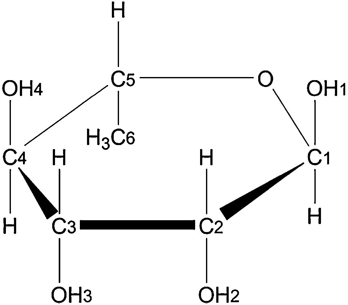 | ||
| Fig. 1 Chemical structure and atomic numbering scheme of α-L-rhamnose. | ||
2. Model system and computational details
The crystallographic unit cell of α-L-rhamnose monohydrate is monoclinic with dimensions a = 7.901 Å, b = 7.922 Å, c = 6.670 Å and β = 95.521°.17 There are two asymmetric units per crystallographic unit cell, each consisting of one rhamnose molecule and one water molecule. The crystalline water molecules contribute to form two infinite hydrogen bond chains through the crystal structure along with hydroxyl groups of the rhamnose molecules, see Fig. 2. One chain is along the b-direction of the crystal [O4–H–Ow–H–]∞ and the other is along the c-direction [O1–H–O2–H–Ow–H–]∞. These two chains are intersecting at the water molecules, and are consequently connected. They have previously been found to play an important role for the selectivity of oxidative radical formation in this crystal.13 To properly include this important feature and to separate radical fragments from their images in the periodic calculations, the crystallographic unit cell was doubled in all directions, yielding a 〈2a2b2c〉 supercell containing 416 atoms.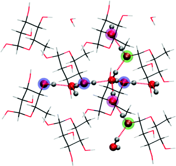 | ||
| Fig. 2 Illustration of hydrogen bond scheme in α-L-rhamnose monohydrate single crystals. Two chains of hydrogen bonds are marked in dotted red. O4 positions are marked in blue, O1 positions are marked in green and O2 positions are marked in magenta. The two hydrogen bond chains intersect at a water molecule. | ||
All calculations were performed with the CP2K program18 and periodic boundary conditions, using the BLYP functional.19,20 Geometry optimizations and MD runs were performed using the Gaussian and plane wave (GPW) method21,22 in which only valence electrons are treated explicitly and the atomic nuclei and core electrons are modeled by GTH pseudo-potentials.23–25 The DZVP-GTH basis was used and the plane wave cutoff was set to 400 Ry. All MD calculations were performed within an NVT ensemble, relying on a canonical sampling through velocity rescaling (CSVR) thermostat26 with a time constant of 10 fs to ensure fast thermal equilibration. Throughout all MD simulations, Mulliken population analysis was used to determine and follow shifts in the spin distribution in each system.
A diagram of the computational sequence is shown in Fig. 3. The neutral crystallographic 〈2a2b2c〉 supercell of rhamnose was optimized and then subject to MD simulations: the structure was first equilibrated to 300 K for 4.4 ps, the run was continued for another 0.5 ps from which 10 geometries were extracted, one every 0.05 ps. These were used as starting points for further MD simulations on charged/damaged systems. For each of the 10 geometries, 16 2-ps MD simulations (Δt = 0.5 fs) were performed: 8 with a cationic (charge +1, spin 1/2) configuration and 8 with an anionic (charge −1, spin 1/2) configuration, equilibrating half of them to 100 K and the other half to 200 K. Altogether 160 ab initio MD runs were performed on charged systems. Variety between the MD runs that started from the same initial geometry was introduced by randomly assigning velocities to the nuclei in the first step of the MD run.
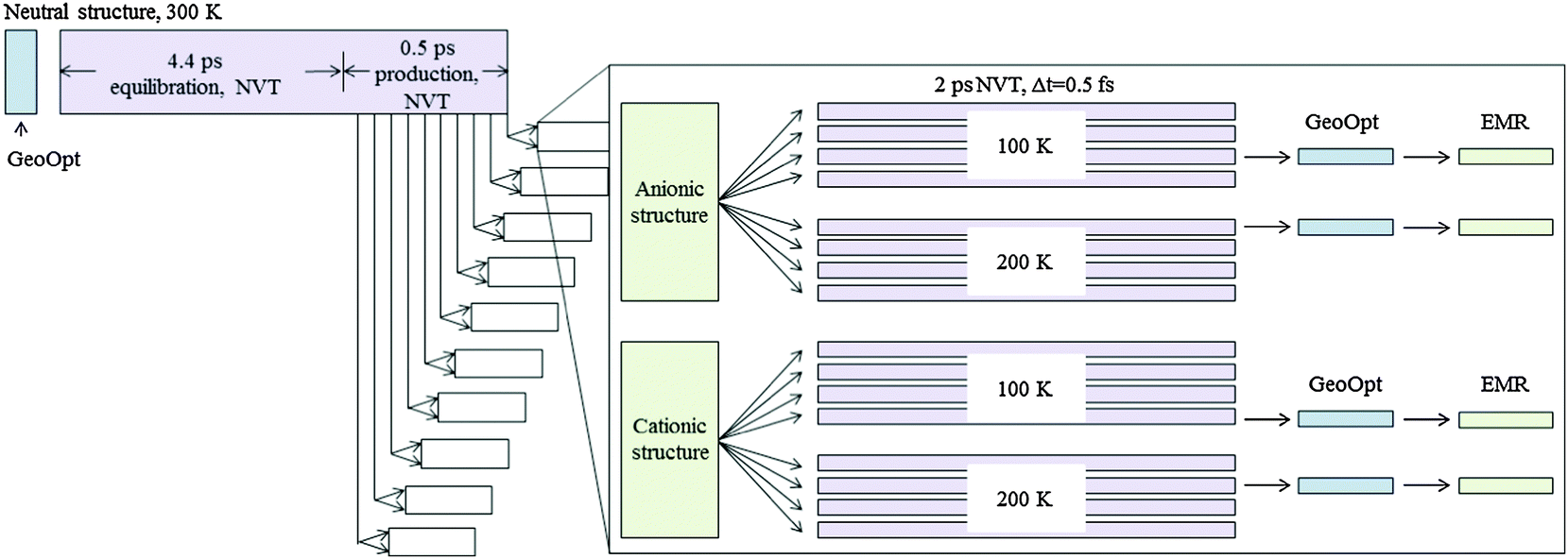 | ||
| Fig. 3 Diagram of computational sequence. From the last 0.5 ps of an MD run on the neutral 〈2a2b2c〉 crystallographic supercell, 10 geometries were selected. For each of these, 16 further MD runs were performed where charge (and spin) was introduced in the system: 8 cationic and 8 anionic, each time with 4 runs at 100 K and 4 runs at 200 K. For each radical type obtained, a representative structure was chosen for further geometry optimization and calculation of EMR properties. | ||
The radicals formed in these MD runs were classified according to initial charge, location of the radical center and chemical structure. For each of the resulting radical type one representative structure was chosen for geometry optimization followed by computation of hyperfine coupling (hfc) tensors. To calculate these EMR properties, the augmented plane wave method27,28 (GAPW) was used in combination with the all electron TZVP basis29 and a plane wave cutoff of 400 Ry. In the instances where radical production in the MD simulation also resulted in the formation of a hydrogen molecule, the final geometry was additionally optimized in the absence of this molecule and EMR properties recalculated. This was motivated by experimental evidence that H2 molecules are able to escape the crystal structures of carbohydrates.30,31
3. Radical formation processes
Radicals were produced in 67 out of the 160 MD simulations performed, in the other instances no spin localization was attained during the 2 ps investigated. In all cases the MD run started out with a spin density distributed over the entire supercell. This density clearly does not describe a radical structure but seemingly the DFT ground state of the chemically intact structures. After a number of MD steps the calculations resulted in a geometrical configuration for the molecules for which the spread out density no longer described the ground state and a conical intersection was crossed. As DFT is not a multi reference method, crossing a conical intersection will not be a smooth process. During the period of crossing the conical intersection, not surprisingly, the temperature of the system increased dramatically due to DFTs lack of ability to produce a physical density for this time period. And during this short time interval, structural changes such as proton transfers and dehydroxylations occurred readily. This, though not a physical process but rather an artifact of DFT, aided the production of radical structures that either stabilized or continued to take part in chemical reactions after a physical density and temperature for the system had been re-established.Common for the MD runs was that protons were easily transferred along the hydrogen bond chains in the crystal structure. These hydrogen bond chains acted as effective transport paths for both positive and negative charge by creating a “current” of positive protons. The readiness of these proton transfers seemed to effect the radical stabilization, and it was observed that the protons were more readily transported in the cationic structures. Also increased temperature contributed to the ease of the proton transfers.
All together 12 different radical species were observed in this study, 7 reduction products and 5 oxidation products. For each initial crystal geometry four different sets of initial velocities were used and different radicals were produced as the initial velocities of the nuclei varied. The initial velocities therefore seem to influence radical production more than the initial geometrical structure itself.
3.1. Reduction products
Seven different reduction products were generated by the MD procedures and these can be divided in to 3 different categories: dehydroxylation, ring-opening and H-atom abstraction. Table 1 lists the different species formed and their frequency of occurrence. Fig. 4 illustrates their chemical structures. In general more reduction product radicals were formed in the higher temperature (200 K) simulations.| Occurrences | Specification | Structure | |
|---|---|---|---|
| Reduction products 100 K | |||
| Dehydroxylation | 6 | 2 × from C1 | (a) |
| 3 × from C2 | (b) | ||
| 1 × form C4 | (c) | ||
| Ring-opening and protonation of ring oxygen | 1 | 1 × scission between C5 and ring oxygen | (d) |
| H-atom abstraction | 1 | 1 × from C5 | (g) |
| Reduction products 200 K | |||
| Dehydroxylation | 20 | 7 × from C1 | (a) |
| 9 × from C2 | (b) | ||
| 5 × from C4 | (c) | ||
| Ring-opening and protonation of ring oxygen | 6 | 5 × scission between C5 and ring oxygen | (d) |
| 1 × scission between C1 and ring oxygen | (e) | ||
| H-atom abstraction | 2 | 2 × from C3 | (f) |
 | ||
| Fig. 4 Reduction product structures. (a)–(c) are dehydroxylation products, (d) and (e) are ring-opened structures, and (f) and (g) are H-atom abstraction products. | ||
The dehydroxylation products (structures (a)–(c) in Fig. 4) were formed when spin localized on a carbon atom which expelled the hydroxyl group attached to this carbon as a hydroxide anion (OH−), leaving behind a neutral radical center. The ejected hydroxide would attract a proton along a preexisting hydrogen bond thereby effectively separating the negative charge from the radical site. Fig. 5 shows a diagram of this reaction. In most cases several proton transfers took place at once, thereby localizing the charge far away from the radical site. Out of the four possibilities, three different dehydroxylation products were observed, namely the C1, C2 and the C4-centered species. The hydroxyl group at C3 does not take part in a hydrogen bond chain, but rather the proton at that site is hydrogen bonded to the ring oxygen of a neighboring rhamnose molecule. It is likely that this structural feature is the reason why no such radical species was observed. Additionally one instance was observed of dehydroxylation from two different rhamnose molecules at once, this resulted in the spin being shared by two molecules, both containing positive charge as they each expelled a hydroxide anion.
 | ||
| Fig. 5 Reductive dehydroxylation product formation. OH− is emitted from radical site and absorbs a proton along a hydrogen bond to form water. The negative charge is moved further away via several proton shuffles along a hydrogen bond chain. | ||
Ring-opened structures were formed when spin localized on either C1 or C5 (structures (e) and (d) in Fig. 4) and the bond between the respective carbon atom and the ring oxygen was ruptured. The negative charge of these radicals was cancelled by protonation at the ring oxygen from the O3 position of an adjacent rhamnose molecule. The charge was moved even further away from the radical site via another proton shuffle from a crystal water. This reaction is shown in Fig. 6.
 | ||
| Fig. 6 Reductive ring-opened product formation. The negative radical molecule absorbs a proton across a hydrogen bond; the proton donor is neutralized by further proton absorption. | ||
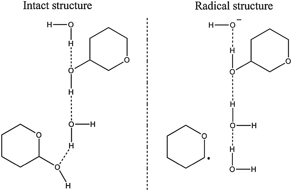
The H-atom abstraction products (structures (f) and (g) in Fig. 4) were formed when spin was localized on the hydrogen from a hydroxyl group in rhamnose. This hydrogen atom was ejected and the negative charge on the hydroxyl oxygen was cancelled by protonation via a hydrogen bond. In this situation both charge and spin migration occurred, though along different routes. This situation is described as the intermediate structure in Fig. 7. The lone hydrogen atom would then recombine with an aliphatic hydrogen abstracted from a different rhamnose molecule; thus forming a neutral hydrogen molecule and localizing the radical center on the H-atom abstracted carbon. This situation is depicted as the radical structure in Fig. 7. Two such radicals were observed in the simulations, one centered on C3 and one centered on C5.
 | ||
| Fig. 7 Reductive H-atom abstraction product formation. Initially, a hydrogen atom is ejected from a hydroxyl group of a rhamnose molecule. The latter is protonated via a hydrogen bond. The lone hydrogen atom in turn abstracts another hydrogen from a carbon site on a neighboring rhamnose molecule. This leads to formation of H2 and leaves the radical center on the H-atom abstracted carbon atom. | ||
3.2. Oxidation products
Five different oxidation products were observed. They are all alkoxy-type radicals, but they were formed via two routes: direct H-atom abstraction from radical center and ring-opening. All radical structures are illustrated in Fig. 8, and the frequency of occurrence for the different species are given in Table 2. It is clear that the oxidative radicals were more easily formed and stabilized at the lower temperature (100 K). | ||
| Fig. 8 Oxidation product structures. (h)–(k) are alkoxy radicals resulting from deprotonation on oxidized hydroxyl group, (l) is a ring-opened structure. | ||
| Occurrences | Specification | Structure | |
|---|---|---|---|
| Oxidation products 100 K | |||
| O1-centered alkoxy | 3 | 2 × stable | (h) |
| 1 × unstable | |||
| O2-centered alkoxy | 6 | 6 × stable | (i) |
| O4-centered alkoxy | 11 | 3 × stable | (k) |
| 8 × unstable | |||
| Ring oxygen-centered | 1 | Concomitant aldehyde formation at C1 | (l) |
| Oxidation products 200 K | |||
| O1-centered alkoxy | 5 | 5 × unstable | (h) |
| O2-centered alkoxy | 5 | 2 × stable | (i) |
| 3 × unstable | |||
| O3-centered alkoxy | 1 | 1 × stable | (j) |
| O4-centered alkoxy | 4 | 1 × stable | (k) |
| 3 × unstable | |||
The structures (h)–(k) were formed as oxygen-centered cationic radicals expelled their surplus charge by transferring a hydroxyl proton to a neighboring molecule via a hydrogen bond. In the case of the O1-, O2 and O4-centered alkoxy radicals (structures (h), (i) and (k) in Fig. 8), the hydroxyl groups take part in the infinite hydrogen bond networks in the crystal structure. The excess positive charge was in these cases effectively separated from the radical site by several proton shuffles along the hydrogen bond chains. This type of reaction is illustrated in Fig. 9.
 | ||
| Fig. 9 Oxidative alkoxy deprotonation product formation. Protons are transferred along hydrogen bonds, separating the charge and spin. | ||
Common for radicals (h), (i) and (k) is that they were not necessarily present throughout the rest of the MD run once they were formed. In some instances ejected protons moved back along the hydrogen bonds; thereby restoring the initial structure. This sometimes occurred even when the charge had been moved across two subsequent hydrogen bonds in the chain. In other instances it was found that the proton transfer pathway was so long the charge migrated to a periodic image of the radical site. This returned the chemical structure of the supercell to the original one, apart from the hydroxyl groups along the hydrogen bond chain, which were now rotated. In many instances this last type of recombination behavior occurred at several places in the crystal simultaneously. These two recombination reactions lead to several transient alkoxy radicals during the MDs run and a net reduction in the number of radicals formed. These transient radicals are included in Table 2.
The O3-centered alkoxy radical (radical structure (j) in Fig. 8) is the result of deprotonation from the O3 hydroxyl group. This hydroxyl group does not take part in the hydrogen bond networks in the crystal, and therefore does not benefit from the efficient way of separating charge and spin. In only one MD simulation, this radical was formed.
There was also one occurrence of two stable O2-centered alkoxy radicals at once. These radicals have a 40–60 split of the electron spin density and both radicals carried negative charge slightly less than half an electron charge. It appears as the two molecules shared the electron hole, and that both expelled a whole proton to compensate for the positive charge.
In addition, one instance of H2 molecule formation was seen in the cationic MD runs. This occurred when a deprotonation chain starting at O1 (of what became a stable alkoxy radical) ended up attracting a hydrogen anion from the C5 position of another rhamnose molecule in the cell. The rhamnose molecule giving up the hydrogen anion went through a ring-opening and a net deprotonation from O1 continuing the chain of positive charge transfer. A schematic of this process is given in the ESI.†
The ring oxygen-centered radical (structure (l) in Fig. 8) is the fifth kind of oxidation product observed. In this radical the ring was broken between the ring oxygen and C1 and the molecule was neutralized by deprotonation from O1 as illustrated in Fig. 10.
 | ||
| Fig. 10 Oxidative ring oxygen-centered product formation. Ring structure is broken and the charge is separated from the spin via several proton transfers along hydrogen bonds. | ||
4. Evaluation of the formed products
4.1. Radical structures and hyperfine coupling tensors
Structures (b), (d)–(g), (k) and (l) were chosen as representative structures for their class and the MD runs were continued until 20 ps was reached. In this time, none of the radical structures evolved further, but rather seemed to be stable. The hydrogen molecules produced remained in the vicinity of where they were produced, but moved around and vibrated within this small area.For the oxidation products, only structure (k), the O4-centered alkoxy radical, was found to have similar hfc tensors as the experimental evidence. This radical has been thoroughly examined before13,14,16 and exhibits a very good agreement with experimental data. The couplings can be found in the ESI.† It is very assuring that previously verified radicals are formed during this process.
After careful examination of the calculated hfc tensors for all reduction radicals produced, only three, (d), (f) and (g), are found to have characteristics comparable to experimentally reported radicals to date. Out of the reduction products only structures (f) and (g) correspond to radical structures suggested by experimentalists on the basis of measured EMR properties,9 whereas (d) has not yet been proposed. The calculated hfc tensors for all structures are given in the ESI.† For both structures (f) and (g), geometries were optimized and hfcs were calculated twice; once with the formed hydrogen molecule present in the crystal structure, and once without this molecule. The presence of the hydrogen molecule apparently did not affect the spin distribution or radical geometry significantly.
Structure (f), the C3-centered H-atom abstraction product, was observed in two different instances in this study, referred to as (f)-I and (f)-II. Mainly the orientation of the dissociated H2 molecule differs between the conformations, as can be seen at the top left in Fig. 11. Both conformations have 78% spin on C3. The calculated hfcs for these two structures are given in Table 3, and it can be seen that they both exhibit one large coupling to H4 with isotropic value of 100 MHz and anisotropy of 12 MHz. Also there are couplings to H2 and HO2 which are similar for the conformations, while there is a significant difference in the isotropic value of the coupling to HO3.
 | ||
| Fig. 11 The two different geometrical conformations of radical (f). Structure (f)-I is shown with black carbon atoms, red oxygen atoms and silver hydrogen atoms. Structure (f)-II is shown with black carbon atoms, green oxygen atoms and blue hydrogen atoms. | ||
| Radical | Atom | (1) H2 molecule present in crystal | (2) H2 molecule removed | (3) Experimental9 | ||||||||
|---|---|---|---|---|---|---|---|---|---|---|---|---|
| A iso | A ani | a* | b | c | Angular deviation (1)–(2) | A iso | A ani | Angular deviation (1)–(3) | A iso | A ani | ||
| f-I | H2 | 12.3 | −5.8 | −0.332 | 0.014 | 0.943 | 1 | 9.9 | −5.7 | 20 | ||
| −3.3 | 0.642 | 0.736 | 0.215 | 1 | −3.3 | |||||||
| 9.0 | −0.691 | 0.677 | −0.253 | 1 | 9.0 | |||||||
| H4 | 100.2 | −5.2 | −0.003 | −0.374 | 0.927 | 2 | 97.8 | −5.1 | 4 | 96.10 | −4.96 | |
| −1.4 | −0.981 | −0.179 | −0.076 | 2 | −1.6 | 4 | −1.77 | |||||
| 6.7 | 0.195 | −0.910 | −0.366 | 0 | 6.7 | 1 | 6.73 | |||||
| HO2 | −4.2 | −7.4 | −0.126 | 0.992 | 0.018 | 1 | −4.1 | −7.4 | ||||
| 0.2 | 0.428 | 0.037 | 0.903 | 1 | 0.2 | |||||||
| 7.1 | 0.895 | 0.122 | −0.429 | 0 | 7.1 | |||||||
| HO3 | 13.9 | −11.0 | −0.522 | 0.608 | 0.598 | 4 | 3.7 | −12.1 | 17–20 | |||
| −8.2 | 0.700 | 0.706 | −0.107 | 1 | −8.9 | |||||||
| 19.2 | −0.487 | 0.362 | −0.794 | 4 | 21.0 | |||||||
| H(H2) | 13.5 | −3.5 | 0.308 | −0.951 | 0.011 | |||||||
| −2.9 | 0.591 | 0.182 | −0.786 | |||||||||
| 6.4 | 0.746 | 0.248 | 0.619 | |||||||||
| f-II | H2 | 7.2 | −5.7 | −0.378 | 0.019 | 0.926 | 2 | 6.1 | −5.7 | 20 | ||
| −3.3 | 0.662 | 0.705 | 0.256 | 2 | −3.3 | |||||||
| 9.0 | −0.647 | 0.709 | −0.278 | 1 | 9.0 | |||||||
| H4 | 101.5 | −4.8 | −0.213 | −0.426 | 0.880 | 1 | 97.4 | −4.8 | 9 | 96.10 | −4.96 | |
| −2.0 | 0.960 | 0.076 | 0.269 | 2 | −2.0 | 9 | −1.77 | |||||
| 6.8 | −0.181 | 0.902 | 0.393 | 1 | 6.7 | 3 | 6.73 | |||||
| HO2 | −4.7 | −8.0 | −0.139 | 0.985 | 0.106 | 1 | −4.6 | −7.9 | ||||
| 0.4 | 0.427 | −0.037 | 0.904 | 1 | 0.4 | |||||||
| 7.6 | 0.894 | 0.171 | −0.415 | 1 | 7.5 | |||||||
| HO3 | 3.4 | −11.2 | −0.444 | 0.617 | 0.650 | 4 | −0.8 | −11.9 | 17–20 | |||
| −8.2 | 0.762 | 0.642 | −0.088 | 3 | −8.8 | |||||||
| 19.4 | −0.471 | 0.456 | −0.755 | 3 | 20.7 | |||||||
| H(H2) | 3.3 | −3.7 | −0.278 | −0.807 | 0.522 | |||||||
| −3.0 | −0.455 | 0.589 | 0.668 | |||||||||
| 6.7 | −0.846 | −0.052 | −0.531 | |||||||||
| H(H2) | 5.3 | −3.7 | −0.504 | 0.831 | 0.236 | |||||||
| −3.4 | −0.414 | −0.472 | 0.778 | |||||||||
| 7.1 | −0.758 | −0.295 | −0.582 | |||||||||
The isotropic value of the HO3 coupling seems to be a sensitive parameter both for the C–OH conformation and for the presence or absence of the H2 molecule in the structure. Fig. 11 compares the geometrical differences between structures (f)-I and (f)-II. As can be seen from the figure, the orientations of the hydroxyl groups in the two structures are quite different, and the angle between the two C3–HO3 directions (HO3I–C3–HO3II) is 7°. It is believed that this difference in orientation is the cause of the discrepancy of 10 MHz in the HO3 isotropic coupling for the two structures. All HO3 couplings have anisotropies of about 30 MHz which increased slightly as the hydrogen molecule in the vicinity was removed. As can also be seen from the figure the hydrogen molecule orientation is very different, resulting in large differences in the hfcs of these atoms. The reorientation of the C3 hydroxyl group upon removal of the hydrogen molecule, was much smaller for each of the structures than the difference in orientation between the structures I and II.
The experimental evidence9 for structure (f) consists of, at 65 K, one large and several smaller hfcs, see also Table 3. The larger one has isotropic value of 96.10 MHz, the full tensor of this coupling was determined after warming to 150 K. Of the smaller couplings, one (about 17–20 MHz) is due to an exchangeable proton, this coupling disappeared upon warming. Another coupling of the same magnitude remained. In comparing the calculated hfcs of the calculated structures to experimental data, it is found that the large H4 coupling of about 100 MHz corresponds well to the experimental observation of a coupling of 96.10 MHz. The experimentally determined tensor is compared to the H4 coupling tensor from the calculations in Table 3. It should be noted that in this case the DFT data are compared to the so-called Schonland conjugate of the experimentally determined tensor.32,33 See the ESI† for details on why this is considered to be correct for this radical. From Table 3 it can be seen that there is good match between the experimental hfcs and theoretical tensors. As for the two smaller couplings: H2 seems to be a good candidate for the observed persisting coupling of about 20 MHz while HO3 could be the exchangeable coupling which disappears upon warming. As the 4 different computed radical structures ((f)-I and (f)-II with and without H2 molecule present) resulted in large differences in isotropic value for the HO3 tensor, a reorientation of the –OH3 group could also explain the experimental data (as is also suggested previously15).
Structure (d), the C5-centered ring-opened structure, was observed in 6 MD simulations in this study. This structure has a spin density of 92% on C5. The hfcs are given in Table 4. The methyl group contains two large and one small coupling, for which the isotropic values average to 66 MHz. There is also one large α-coupling with isotropic value of −48 MHz and anisotropy of 70 MHz due to interaction with H5. Smaller couplings to H4, HO4 and the proton added to ring oxygen are also present.
| Radical | Atom | (1) MD produced structure (H2 molecule present for (g)) | (2) H2 molecule removed | (3) Experimental9 | ||||||||
|---|---|---|---|---|---|---|---|---|---|---|---|---|
| A iso | A ani | a* | b | c | Angular deviation (1)–(2) | A iso | A ani | Angular deviation (1)–(3) | A iso | A ani | ||
| d | H4 | 8.4 | −5.8 | −0.233 | −0.901 | 0.365 | ||||||
| −3.0 | 0.589 | 0.168 | 0.790 | |||||||||
| 8.9 | −0.773 | 0.400 | 0.492 | |||||||||
| H5 | −48.2 | −34.3 | −0.439 | −0.405 | 0.802 | 95 | ||||||
| −3.3 | 0.713 | 0.387 | 0.585 | |||||||||
| 37.6 | −0.547 | 0.829 | 0.119 | |||||||||
| H6 | 103.7 | −4.8 | 0.981 | −0.188 | −0.041 | 56 | ||||||
| −3.2 | 0.189 | 0.906 | 0.379 | |||||||||
| 8.1 | 0.034 | 0.379 | −0.925 | |||||||||
| H6 | 91.8 | −4.9 | −0.028 | 0.668 | 0.744 | 56 | ||||||
| −3.6 | 0.831 | −0.398 | 0.388 | |||||||||
| 8.4 | 0.555 | 0.629 | −0.544 | |||||||||
| H6 | 2.0 | −4.3 | 0.796 | −0.073 | −0.600 | 56 | ||||||
| −3.6 | 0.571 | 0.419 | 0.706 | |||||||||
| 7.8 | −0.200 | 0.905 | −0.376 | |||||||||
| HO4 | −5.3 | −9.1 | −0.995 | −0.042 | −0.088 | |||||||
| −1.5 | −0.067 | −0.365 | 0.929 | |||||||||
| 10.6 | −0.071 | 0.930 | 0.360 | |||||||||
| HO ring | 9.4 | −3.5 | −0.730 | 0.574 | 0.372 | |||||||
| −1.5 | −0.427 | −0.807 | 0.408 | |||||||||
| 5.0 | −0.534 | −0.139 | −0.834 | |||||||||
| g | H4 | 99.0 | −5.5 | 0.628 | 0.778 | 0.022 | 1 | 95.4 | −5.4 | 95 | ||
| −1.3 | 0.563 | −0.474 | 0.677 | 4 | −1.4 | |||||||
| 6.8 | −0.537 | 0.413 | 0.735 | 4 | 6.8 | |||||||
| H6 | 31.9 | −4.7 | −0.004 | 0.892 | 0.451 | 58 | 37.0 | −4.7 | 56 | |||
| −4.1 | 0.862 | −0.225 | 0.453 | 57 | −4.5 | |||||||
| 8.8 | 0.506 | 0.391 | −0.769 | 3 | 9.2 | |||||||
| H6 | 14.8 | −4.9 | 0.069 | 0.028 | 0.997 | 14 | 14.6 | −4.8 | 56 | |||
| −4.0 | 0.780 | −0.624 | −0.036 | 14 | −4.4 | |||||||
| 8.9 | 0.622 | 0.781 | −0.065 | 3 | 9.2 | |||||||
| H6 | 108.3 | −4.1 | 0.140 | 0.480 | 0.866 | 4 | 122.9 | −4.0 | 56 | |||
| −2.6 | 0.987 | −0.137 | −0.083 | 4 | −2.6 | |||||||
| 6.7 | 0.079 | 0.866 | −0.493 | 2 | 6.6 | |||||||
| H(H2) | 84.0 | −3.1 | 0.134 | 0.392 | 0.910 | |||||||
| −2.7 | −0.324 | −0.851 | 0.414 | |||||||||
| 5.8 | 0.937 | −0.350 | 0.013 | |||||||||
| H(H2) | −11.2 | −13.6 | 0.163 | 0.408 | 0.898 | |||||||
| −11.2 | −0.308 | −0.844 | 0.439 | |||||||||
| 24.8 | 0.937 | −0.348 | −0.012 | |||||||||
Structure (g), the C5-centered H-atom abstraction product, was only observed in one MD run. The spin on this radical is localized with 81% on C5. Upon removal of the hydrogen molecule from the crystal structure, the geometry did not change much, but the spin density on C5 increased to 84%. The hfcs of the radicals, shown in Table 4, are dominated by two large isotropic couplings of about 100 MHz. Both are β-couplings, one to H4 and another to one of the methyl protons. The other two methyl protons are also interacting significantly with the unpaired spin. As the methyl group is likely to be rotating even at relatively low temperatures, the average value of these, being about 50–60 MHz, is more interesting. One of the H2 protons exhibits a large coupling of 84 MHz, but whether or not this hydrogen molecule is present in the crystal structure with radical (g) does not seem to have large impact on the hfcs of the radical. The C6 methyl group couplings increased somewhat upon removal of the hydrogen molecule, but this is most likely linked to the concomitant increase in spin density on C5.
Also structure (g) was previously proposed to be observed experimentally.9 The experimental evidence is an EPR spectrum which is a doublet of quartets, assumedly due to couplings to a proton and a rotating methyl group. Both couplings are relatively isotropic. The magnitude of the experimentally determined proton coupling was about 95 MHz and the methyl group coupling was measured to about 56 MHz, but full hfc tensors were not determined for this radical. In the present study, only structures (d) and (g) display methyl group couplings of the right magnitude, as well as one other large coupling. These radicals are both C5-centered and the main difference between them is that (d) exhibits an α-proton coupling to H5, whereas (g) exhibits a β-proton coupling to H4. As the experimental evidence is of a relatively isotropic coupling,9 the (d) candidate may likely be eliminated. A further verification of this radical candidate is not possible until more detailed experimental data are available.
4.2. Hydrogen gas formation
The formation of hydrogen gas (H2) upon irradiation has been experimentally observed for a number of carbohydrates30,31,34–36 as well as amino acids.37 Hydrogen is generally found to be the major gaseous product formed. In particular, investigations on α-D-glucose and α-D-glucose monohydrate has shown that about 70% of the hydrogen gas formed is trapped inside the crystal lattice.30,31 Similar studies on rhamnose do not exist to the best of our knowledge. The results in the present work indicate that the formation of hydrogen molecules is intrinsic for one type of radical formed, the H-atom abstraction products. According to our calculations on structure (f) it seems that trapped H2 molecules lead to alterations in the hfcs of the radical even when the geometrical structure of the radical is not much influenced by the presence of H2 in the lattice. The increased isotropic values of the hfcs of the radicals might therefore reveal H2 even if protons of the hydrogen molecule itself do not possess sufficiently large hfcs for detection by EMR.5. Conclusions
A method for exploring possible radical structures as resulting from radiation exposure has been presented. This method has the advantage of providing a selection of possible radiation damage products without bias by the expectations of the scientist. The method generates a number of different radical structures which need to be examined further and compared to experimental data. In this particular work dehydroxylation products as well as ring-opened structures were produced. These are not structures that would normally be explored to a large extent.Starting from an intact crystal structure and introducing spin and charge to this, ionization events are mimicked. In an actual ionization event in nature, there will be a high localization of energy, and for this reason it is necessary to describe reactions over barriers that cannot be crossed using only the thermal energy available. Although the initial DFT ground state is one where the spin and charge is delocalized in the system, the time evolution of the system leads to a conformation where this is no longer the ground state. The failure of DFT to describe conical intersections properly is then exploited in the radical formation as the temperature rises for a brief time period and high reaction barriers can easily be crossed.
In a previous study13 it was found that several alkoxy radicals are stable, but the relative energies may explain that the relative abundances of these species are such that only one radical is observable in experiments. The present simulations do not reproduce these relative abundances of radicals. The short-time increase in temperature at the moment of radical production in our simulations practically removes reaction barriers, as would also be expected from a physical ionization event. On the other hand, the thermal equilibration expected to allow for transformation of one type of radical into the other is not seen in the calculations. This is likely due to the short time span of the calculations.
The diversity of the radicals produced is caused by three initial conditions: the initial molecular geometries and atomic velocities in the MD-runs and the temperature of the thermostat. As four runs with different initial velocities were performed for each initial geometrical structure, the relative importance of these effects could be examined. It was clear that the initial velocities were decisive in which radicals were formed and where in the cell they were localized, more than the initial geometrical conformations.
The effect of temperature was opposite in the cases of reduction and oxidation products. A higher temperature increased the activity of proton transfer over the hydrogen bond network. In the case of cationic species this became an over-activity causing problems with radical formation as the charge migration sometimes looped due to the periodic boundary conditions. In anionic species on the other hand, the proton transfer activity was generally lower and the higher temperature was needed to gain sufficient charge transport for stabilization of radicals. These proton transfer reactions occur in nature, and contribute to charge–spin separation thereby stabilizing radicals, as was also seen in these simulations.
It is also satisfying that the method seems to produce all types of experimentally observed molecular radicals reported in literature on the system. The only radical not seen here is a C2-centered H-atom abstraction product.9 There is of course the possibility that this event would have been observed if even more exhaustive sampling with the aid of MD simulations was performed. But as similar H-atom abstraction products are formed, the data at hand would already alert the scientist to the possibility of such a radical as well as the C3- and C5-centered versions. This possibility is not explored further in this work, as the C2-centered radical model has been confirmed by DFT simulation at an earlier stage.15
In the future it will be interesting to apply this computational procedure to other systems where there is experimental evidence for radicals which are at present unidentified, such as trehalose3,4 and sucrose.38 The method produces structures which have not previously been considered, and it is possible that this will lead to one or more structures that correspond with the experimental data.
Acknowledgements
The computational resources (Stevin Supercomputer Infrastructure) and services used in this work were provided by the VSC (Flemish Supercomputer Center), funded by Ghent University, the Hercules Foundation and the Flemish Government – department EWI. A. Van Yperen-De Deyne acknowledges the Research Board of Ghent University (BOF) for funding. S. G. Aalbergsjø acknowledges PhD fellowship and travel grants from the University of Oslo.References
- H. Vrielinck, H. De Cooman, F. Callens and E. Sagstuen, in Applications of EPR in Radiation Research, ed. M. Shiotani and A. Lund, Springer, Berlin, 2014, to be published Search PubMed.
- M. A. Tarpan, H. Vrielinck, H. De Cooman and F. Callens, J. Phys. Chem. A, 2009, 113, 7994–8000 CrossRef CAS PubMed.
- H. De Cooman, M. A. Tarpan, H. Vrielinck, M. Waroquier and F. Callens, Radiat. Res., 2013, 179, 313–322 CAS.
- M. A. Tarpan, H. De Cooman, E. O. Hole, M. Waroquier and F. Callens, J. Phys. Chem. A, 2012, 116, 3377–3387 CrossRef CAS PubMed.
- H. De Cooman, E. Pauwels, H. Vrielinck, E. Sagstuen, M. Waroquier and F. Callens, J. Phys. Chem. B, 2010, 114, 666–674 CrossRef CAS PubMed.
- E. Pauwels, in Applications of EPR in Radiation Research, ed. M. Shiotani and A. Lund, Springer, Berlin, 2014, to be published Search PubMed.
- H. Tachikawa and T. Fukuzumi, PCCP Phys. Chem. Chem. Phys., 2011, 13, 5881–5887 RSC.
- H. Tachikawa and T. Takada, Chem. Phys., 2013, 415, 76–83 CrossRef CAS PubMed.
- E. Sagstuen, M. Lindgren and A. Lund, Radiat. Res., 1991, 128, 235–242 CrossRef CAS.
- P. O. Samskog and A. Lund, Chem. Phys. Lett., 1980, 75, 525–527 CrossRef CAS.
- E. E. Budzinski and H. C. Box, J. Chem. Phys., 1985, 82, 3487–3490 CrossRef CAS PubMed.
- P. O. Samskog, A. Lund, G. Nilsson and M. C. R. Symons, J. Chem. Phys., 1980, 73, 4862–4866 CrossRef CAS PubMed.
- S. G. Aalbergsjø, E. Pauwels, H. De Cooman, E. O. Hole and E. Sagstuen, PCCP Phys. Chem. Chem. Phys., 2013, 15, 9615–9619 RSC.
- E. Pauwels, R. Declerck, V. Van Speybroeck and M. Waroquier, Radiat. Res., 2008, 169, 8–18 CrossRef CAS PubMed.
- E. Pauwels, V. Van Speybroeck and M. Waroquier, J. Phys. Chem. A, 2006, 110, 6504–6513 CrossRef CAS PubMed.
- E. Pauwels, T. Verstraelen and M. Waroquier, Spectrochim. Acta, Part A, 2008, 69, 1388–1394 CrossRef PubMed.
- S. Takagi and G. A. Jeffrey, Acta Crystallogr., Sect. B: Struct. Crystallogr. Cryst. Chem., 1978, 34, 2551–2555 CrossRef.
- the CP2K developers group, CP2K version 2.4 (Development Version), 2013 Search PubMed.
- A. D. Becke, Phys. Rev. A: At., Mol., Opt. Phys., 1988, 38, 3098–3100 CrossRef CAS.
- C. T. Lee, W. T. Yang and R. G. Parr, Phys. Rev. B: Condens. Matter Mater. Phys., 1988, 37, 785–789 CrossRef CAS.
- G. Lippert, J. Hutter and M. Parrinello, Mol. Phys., 1997, 92, 477–487 CrossRef CAS.
- J. VandeVondele, M. Krack, F. Mohamed, M. Parrinello, T. Chassaing and J. Hutter, Comput. Phys. Commun., 2005, 167, 103–128 CrossRef CAS PubMed.
- S. Goedecker, M. Teter and J. Hutter, Phys. Rev. B: Condens. Matter Mater. Phys., 1996, 54, 1703–1710 CrossRef CAS.
- C. Hartwigsen, S. Goedecker and J. Hutter, Phys. Rev. B: Condens. Matter Mater. Phys., 1998, 58, 3641–3662 CrossRef CAS.
- M. Krack, Theor. Chem. Acc., 2005, 114, 145–152 CrossRef CAS.
- G. Bussi, D. Donadio and M. Parrinello, J. Chem. Phys., 2007, 126, 7 CrossRef PubMed.
- M. Krack and M. Parrinello, Phys. Chem. Chem. Phys., 2000, 2, 2105–2112 RSC.
- G. Lippert, J. Hutter and M. Parrinello, Theor. Chem. Acc., 1999, 103, 124–140 CrossRef CAS.
- N. Godbout, D. R. Salahub, J. Andzelm and E. Wimmer, Can. J. Chem., 1992, 70, 560–571 CrossRef CAS.
- G. O. Phillips and P. Baugh, Nature, 1963, 198, 282–283 CrossRef CAS.
- G. O. Phillips and P. J. Baugh, J. Chem. Soc. A, 1966, 370–377 RSC.
- D. S. Schonland, Proc. Phys. Soc., 1959, 73, 788–792 CrossRef.
- H. Vrielinck, H. De Cooman, M. A. Tarpan, E. Sagstuen, M. Waroquier and F. Callens, J. Magn. Reson., 2008, 195, 196–205 CrossRef CAS PubMed.
- M. Dizdaroglu, D. Henneberg, K. Neuwald, G. Schomburg and C. von Sonntag, Z. Naturforsch., B: J. Chem. Sci., 1977, 32, 213–224 Search PubMed.
- A. G. W. Bradbury and C. von Sonntag, Z. Naturforsch., B: J. Chem. Sci., 1977, 32, 725–726 Search PubMed.
- G. Löfroth and T. Gejvall, Acta Chem. Scand., Ser. B, 1974, 28, 777–780 CrossRef PubMed.
- T. Gejvall and G. Löfroth, Radiat. Eff. Defects Solids, 1975, 25, 187–190 CrossRef CAS.
- H. De Cooman, J. Keysabyl, J. Kusakovskij, A. Van Yperen-De Deyne, M. Waroquier, F. Callens and H. Vrielinck, J. Phys. Chem. B, 2013, 117, 7169–7178 CrossRef CAS PubMed.
Footnote |
| † Electronic supplementary information (ESI) available. See DOI: 10.1039/c4cp02179g |
| This journal is © the Owner Societies 2014 |