 Open Access Article
 This Open Access Article is licensed under a
 Creative Commons Attribution 3.0 Unported Licence
Recovery of dye-sensitized solar cell's performance by heat treatment†
Marko
Berginc
*,
Marko
Topič
and
Urša
Opara Krašovec
Faculty of Electrical Engineering, University of Ljubljana, Tržaška 25, SI-1000 Ljubljana, Slovenia. E-mail: marko.berginc@fe.uni-lj.si
First published on 25th April 2014
Abstract
The formation of iodine containing crystals with ageing in ionic liquid based dye-sensitized solar cells (DSSCs) containing an I3−/I− redox couple has already been confirmed. In this report we show how the size of these crystals can reversibly change during operation and the effects this has on cell performance. We also show how heat treatment and applied forward and reverse current treatment influence crystal growth in the cell. Crystal growth was tracked using electroluminescence and transmittance imaging, while current–voltage characterization and electrical impedance spectroscopy were used to measure cell performance and follow the changes in I3− diffusion, charge transfer resistance, and recombinations occurring in the DSSCs. Results reveal that applying a reverse current to the DSSC leads to the rapid formation of H2 bubbles while crystals grow rapidly when a forward current is applied. Additionally heat treatment at 80 °C can completely recover performance of a degraded cell showing visible defects and a large inhomogeneous active area.
 Marko Berginc | Marko Berginc received his PhD from the Faculty of Electrical Engineering at the University of Ljubljana in 2009 where he currently works as a researcher. His research interests include characterization and modelling of dye-sensitized solar cells, focusing mainly on the influence of cell temperature and light intensity. He is currently working on plasmonic effects and stability studies for dye sensitized solar cells. |
 Marko Topič | Marko Topič received his PhD from the Faculty of Electrical Engineering at the University of Ljubljana in 1996. Currently he is a Full Professor at University of Ljubljana and an Affiliate Professor at Colorado State University. His research interests include photovoltaic, thin-film semiconductor materials, electron devices, optoelectronics, electronic circuits, and reliability engineering. Prof. Topič acts as the President of the MIDEM Society and is a member of the Steering Committee of the European Photovoltaic Technology Platform. |
 Urša Opara Krašovec | Urša Opara Krašovec received her PhD from the Faculty of Chemistry at the University of Ljubljana in 1999. Currently she is a senior scientist at the University of Ljubljana, Faculty of Electrical Engineering. Her research interests cover the field of materials science – developing different kinds of materials/layers/components for devices that are connected to solar energy (e.g., solar cells and smart windows) and printed optoelectronic devices. |
1 Introduction
Dye-sensitized solar cells (DSSCs) have been extensively studied as low-cost alternatives to silicon solar cells.1,2 Over the last two decades various materials including dyes and electrolyte components have been developed with the aim of improving conversion efficiency and cell stability. Despite this cell stability remains an issue.3–11 Photovoltaic cells/modules must pass tests related to stability as specified in the IEC 61646 or IEC 61215 standards to qualify for the market. In addition solar cells are expected to pass specific industry-driven tests of which the most challenging for DSSC technology remains the light soaking test at 85 °C,5 while the thermal test at 85 °C in the dark and the light soaking test under full sunlight at 60 °C6,12 are slightly less demanding.Cell or PV module aging can be done both indoors starting with temporal stability testing in the dark at room temperature, albeit more usually under continuous accelerated conditions, or outdoors under location-specific and field-specific (year/season/day) conditions. Generally, regardless of the type of ageing, a progressive decrease in performance parameters i.e. short circuit current JSC, open circuit voltage VOC and, fill factor FF and conversion efficiency (η) is expected. This is not always the case and variations in these performance parameters occur during ageing under different conditions,6,10,12–21 which at times can even recover the η of an aged cell at a certain stage. One example is the decrease in JSC which accompanies an increase in FF due to reduced serial resistance losses.11 Some variations that occur with ageing are more difficult to explain. For instance the increase in VOC, which is thought to be a result of an upward shift of the TiO2 Fermi level, will decrease the JSC due to reduced electron injection from the excited dye into the TiO2.13,17 A similar increase in VOC and FF and a decrease in JSC and η were also observed by Kim et al.22 who periodically measured the performance of DSSCs stored in the dark for 43 days under standard test conditions (STC). The change in performance was ascribed to the growth of dark coloured needle-shaped solid crystals on the TiO2 layer appearing 10 days after fabrication.22 Fourier transform infrared spectroscopy indicated that these crystals are related to dye becoming detached from the TiO2 surface in the presence of guanidinium thiocyanate in the electrolyte, since guanidine can react with water present in the cell to form ammonia – a dye desorbing agent.22 Alternatively, Fischer et al.23 found dark brown, almost black crystals in their DSSCs after one to two weeks. This occurred when N-methylbenzimidazole (MBI) was added to an I3−/I− based electrolyte with 3-methoxypropionitrile (MPN) as a solvent. The change in the colour of the electrolyte from dark brown to yellow-orange is indicative of a substantial amount of iodine-containing species leaving the liquid phase.23 The authors proposed that MBI interacts with I3− ions in the electrolyte to form neutral and/or ionic complexes, such as (MBI)6(MBI-H+)2(I−)(I3−), which has been confirmed by X-ray diffraction.23 The crystals consisted of six neutral and two protonated MBI fragments while I− and I3− anions balance the overall charge. The organic layers are separated by inorganic layers with alternating I− and linear I3− anions forming infinite chains along the crystallographic a-axis.23
In our previous studies we examined such crystals using the light-beam-induced current technique, transmittance imaging (TI) and electroluminescence (EL).11,24,25 These methods allowed us to study local defects.24 Electroluminescence imaging demonstrated that short term ageing (irradiation ≤ 30 kW h m−2) is associated with crystal growth in the electrolyte.25 Under an open-circuit condition crystal growth increased both VOC and η, while under a short-circuit condition crystal growth was more pronounced and a decrease in JSC, VOC and η was observed.25 More recently we revealed that the dark crystals are introduced into the cells along with the electrolyte.11 We also found that these crystals continued to grow when the cells were stored in the dark causing an increase in VOC and a decrease in JSC, but dissolved during the first 2 months of a 7 month outdoor ageing study (irradiation ≤ 909 kW h m−2) regardless of the operating condition.11 Interestingly, one large crystal typically grew during the final stage of ageing under open-circuit conditions.11
Because the formation/growth/dissolution of iodine based crystals in the electrolyte significantly influences the performance of DSSCs we believe that it is important to understand the correlation between crystal development and cell performance. For this reason we have studied the effect of crystal development in cells that were (i) kept in the dark at standard room temperature (25 °C), (ii) exposed to heat, and (iii) subjected to either a forward or reverse current. Temperatures of 60 °C and 80 °C were chosen for heat treatment since cell temperature when outdoors can exceed 60 °C.8,26 Reverse or forward currents proportional to the JSC were also applied to non-illuminated cells to simulate shade conditions for cells connected in either series or parallel in a PV module. The EL and TI were used to track crystal development while current–voltage characterization (I–V) and electrical impedance spectroscopy (EIS) were used to correlate cell performance with processes occurring in the cells such as I3− diffusion, charge transfer resistance, and recombinations.
2 Experimental
2.1 Cell preparation
A fluorine-doped SnO2 coated glass (TCO) with a sheet resistance of 8 Ω/□ was used for the front and back cell substrate. An optimized Pechini sol–gel TiO2 paste (based on P25, Degussa, Germany)27 was then applied to the surface of the front TCO glass substrate using the “doctor blading” technique. The TiO2 layer was then sintered at 450 °C for 1 h before being immersed for 12 h in an ethanol solution of a Ruthenium complex based dye N719 (Ru(2,2′bipyridyl-4,4′dicarboxylate)2 (NCS)2, Solaronix, Switzerland). For a counter electrode, platinum (thickness ∼5 nm) was sputtered on a TCO glass substrate. The active and counter electrodes were then sealed using a 25 μm thick polymer foil frame (Surlyn, DuPont, USA). This also acts as a spacer between the two electrodes. As an electrolyte we used a binary ionic–liquid mixture of 1-propyl-3-methyl-imidazolium iodide (Iolitec) and 1-ethyl-3-methyl-imidazolium tetracyanoborate in a volume ratio of 13![[thin space (1/6-em)]](https://www.rsc.org/images/entities/char_2009.gif) :7 (Merck), with the addition of 0.5 M N-methylbenzimidazole, 0.1 M guanidinium thiocyanate and 0.2 M of I2. This composition is considered the best binary ionic liquid electrolyte for DSSCs.28 After injecting the electrolyte through two pre-drilled holes in the counter electrode the cells were sealed and stored in the dark for 24 h to allow for complete penetration of electrolyte into the pores of the TiO2 layer. The size of the active area was 0.63 ± 0.05 cm2.
:7 (Merck), with the addition of 0.5 M N-methylbenzimidazole, 0.1 M guanidinium thiocyanate and 0.2 M of I2. This composition is considered the best binary ionic liquid electrolyte for DSSCs.28 After injecting the electrolyte through two pre-drilled holes in the counter electrode the cells were sealed and stored in the dark for 24 h to allow for complete penetration of electrolyte into the pores of the TiO2 layer. The size of the active area was 0.63 ± 0.05 cm2.
2.2 Characterization
Cells under test were routinely characterized at different times according to Table 1. The I–V scan under STC, the electroluminescent image (EL) and the transmission image (TI) were always used for characterization. After initial characterization (phase a) the cells were stored in the dark at room temperature (RT, 25 °C) under an open-circuit condition for an initial resting period of 11 months (1st resting period). The cells were then treated as described in Table 1 (phase b). After each heat treatment (each time period and temperature) the cells were cooled down prior to taking the I–V scan under STC. After phase b the cells were rested for a second time (2nd resting period) in the dark at RT under an open-circuit condition for a further 9 months. After resting the cells were then characterized again (phase c1) before being heated at 80 °C for 8 h in the dark under an open-circuit condition (phase c2). During heat treatment the cells were stored in the dark under open-circuit conditions. A series of reference cells were also stored in the dark at RT.| Phase | Heat treatment | Reverse bias current | Forward bias current |
|---|---|---|---|
| Cell 1/cell 2/cell 3 | Cell 4 | Cell 5 | |
| a Not shown. | |||
| a | I–V, EL, TI | I–V, EL, TI | I–V, EL, TI |
| 11 months/dark, RT | 11 months/dark, RT | 11 months/dark, RT | |
| b | I–V, EL, TI | I–V, EL, TI | I–V, EL, TI |
| 5 min at RT/60 °C/80 °C | 5 min 30 s at 0.2 × JSC, TI | 6 h 40 min at −JSC, TI | |
| I–V, EL, TI | 6 h 40 min at JSC, TI | 17 h 30 min at −2 × JSC, TI | |
| 10 min at RT/60 °C/80 °C | 18 h at 2 × JSC, TI | 66 h at −2 × JSC, TI | |
| I–V, EL, TI | I–V, EL, TI | I–V, EL, TI | |
| 15 min at RT/60 °C/80 °C | 1 h at 80 °C | 1 h at 80 °C | |
| I–V, EL, TI | I–V, EL, TI | I–V, EL, TI | |
| 30 min at RT/60 °C/80 °C | — | — | |
| I–V, EL, TI | — | — | |
| 60 min at RT/60 °C/80 °C | — | — | |
| I–V, EL, TI | — | — | |
| 2 h at RT/60 °C/80 °C | — | — | |
| I–V, EL, TI | — | — | |
| 2 h at RT/60 °C/80 °C | — | — | |
| I–V, EL, TI | — | — | |
| 9 months/dark, RT | 9 months/dark, RTa | 9 months/dark, RTa | |
| c1 | I–V, EL, TI | I–V, EL, TIa | I–V, EL, TIa |
| 8 h at 80 °C | 8 h at 80 °Ca | 8 h at 80 °Ca | |
| c2 | I–V, EL, TI | I–V, EL, TIa | I–V, EL, TIa |
3 Results and discussion
3.1 Heat treatment
Electroluminescent images and performance parameters (JSC, VOC, FF and η) of the reference cell (cell 1) and the cells heat treated at 60 °C (cell 2) and 80 °C (cell 3) are presented in Fig. 1 and 2, respectively. For the reference cell the same measurement protocol and timeline as for the heat treated cells were applied (see Experimental). This means that any changes observed in cell performance and crystal development in the reference cell are results of repeated I–V scans and EL image acquisitions. Herein, only the progress of a typical DSSC for each temperature is presented. The performance parameters of these cells and an additional cell at each temperature together with TI and EL images with additional intermediate snapshots are given in the ESI† (Table S1 and Fig. S2 and S3, respectively).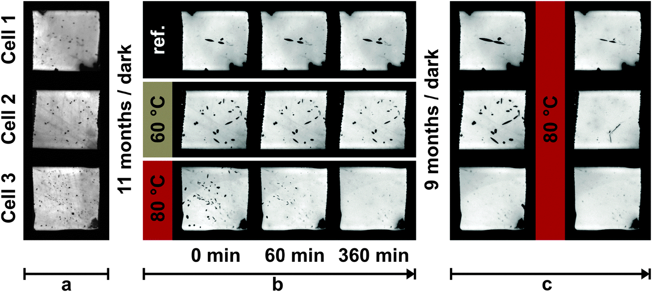 | ||
| Fig. 1 The EL images of a reference cell and cells heated at 60 °C and 80 °C (phase b). Additionally EL of the cells before the 1st resting period (phase a), after the 2nd resting period and after additional heat treatment at 80 °C for 8 h (phase c) are given. More frequent snapshot and EL images of additional cells are given in Fig. S2 in the ESI.† | ||
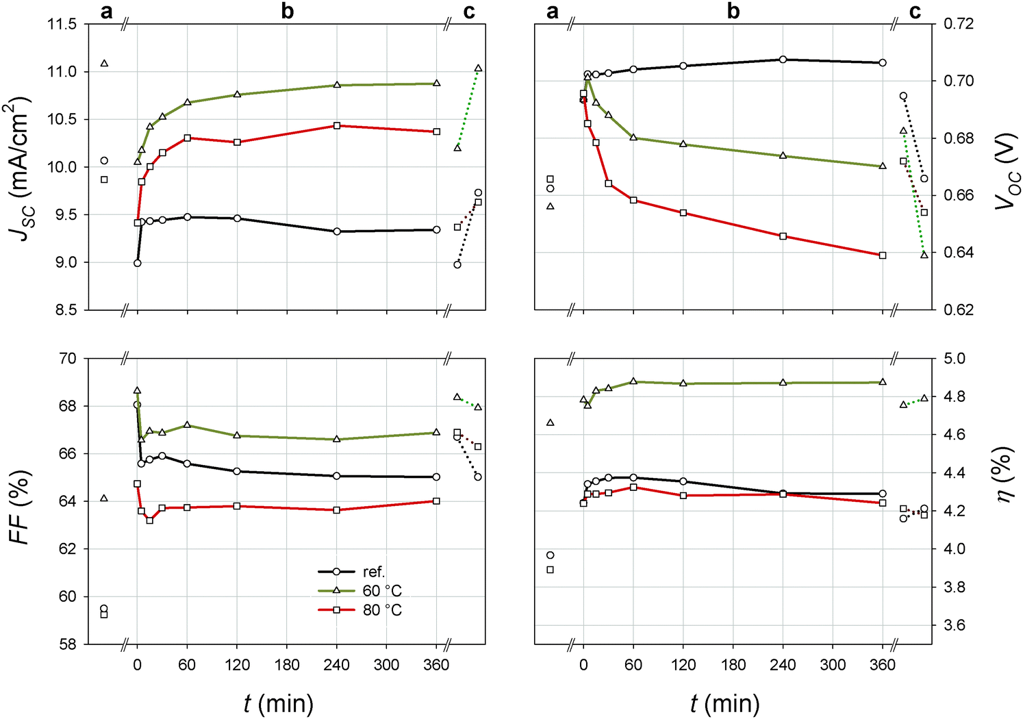 | ||
| Fig. 2 Performance parameters: JSC, VOC, FF and η of the reference cell and cells heated at 60 °C or 80 °C for different time periods (phase b). Additionally the performances that were measured 11 months prior to heat treatment (phase a), 9 months after the treatment and after additional heat treatment at 80 °C for 8 h (phase c) are also given. | ||
Heat treatment at 60 °C (cell 2) and 80 °C (cell 3) affects both cell performance and crystal size. The crystals in cells 2 and 3 gradually dissolve during heat treatment (Fig. 1) with dissolution being significantly faster at 80 °C compared to 60 °C. Our EL measurements show that the crystals completely disappeared in the cells exposed to 80 °C for 4 h (ESI,† Fig. S2). When exposed to 60 °C for 6 h the crystals did not disappear but were significantly reduced in size (Fig. 1). The dissolution of the crystals also affects cell performance. The JSC of the cell exposed to 60 °C and the cell exposed to 80 °C logarithmically increased with time. This initial increase in the JSC may, in part, be related to the reactivation of the DSSC due to repeated I–V measurements as observed for the reference cell. Nevertheless, a more intense and rapid increase in JSC is observed when the cells were heated at 80 °C (cell 3) and is related to the rapid dissolution of the crystals. The JSC of cell 3 after being heated for 6 h (phase b) exceeds the initial JSC (phase a), while remaining below the initial JSC in the case of cell 2. The JSC of cell 2 (treated at 60 °C) monotonically increased with time, whereas JSC decreases during the final 2 h of heat treatment at 80 °C (cell 3). Similar observations were found for the equally treated cell 3a (Table S1 in the ESI†). We believe that this decrease in JSC is probably related to a degradation of the electrolyte, an observation affirmed by electrical impedance spectroscopy (see below).
The dissolution of the iodine containing crystals in cells 2 and 3 also leads to an increase [I3−] in the electrolyte, which shifted the redox potential of the electrolyte upward and stimulated recombinations. Both mechanisms decrease the VOC, which is confirmed by the exponential decrease in VOC with time (Fig. 2). According to expectations the observed reduction in VOC is faster and more intensive in the case of cell 3. The FF sharply decreases during the first 30 min but then remains unaffected. This is a probable result of serial resistance losses due to the sudden initial increase in the JSC. With the exception of a minor initial fluctuation, η remained stable during heat treatment at both 60 °C and 80 °C, although significant variations in JSC and VOC were observed (Fig. 2).
The electrolyte used in our study contained both guanidinium thiocyanate and the N-methylbenzimidazole which means that the crystals could originate from either dye desorption as proposed by Kim et al.22 or are crystals of (MBI)6(MBI-H+)2(I−)(I3−) as proposed by Fischer et al.23 In our case, crystallization is best explained by the formation of a iodine containing crystal such as an (MBI)6(MBI-H+)2(I−)(I3−) complex.23 First, the crystals were introduced into the cells along with the electrolyte (phase a) and second, the JSC decreased and the VOC increased as the crystals grew. This can be correlated with the variation in [I3−] but cannot be explained by dye desorption, since the presence of an undyed TiO2 surface acting as a strong recombination centre would cause a decrease in VOC. Finally, heat treatment demonstrated the reversibility of the process, which is related to crystal growth/dissolution – a fact that supports the presence of iodine containing crystals. After heat treatment the VOC decreased while JSC increased possibly to its highest recorded value (cell 3, Fig. 2). Such an increase would be unlikely if crystal formation was a result of dye desorption.
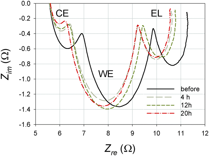 | ||
| Fig. 3 Nyquist plots of the EIS spectra of a typical illuminated DSSC under open-circuit conditions. The spectra were measured before and after being heated at 80 °C for 4, 12 and 20 h. The high, central and low frequency semicircles relate to processes at the counter electrode (CE), the working electrode (WE) and in the electrolyte (EL), respectively. | ||
A typical Nyquist plot of the EIS spectrum consists of three semicircles each measured in a different frequency range; a high frequency semicircle describes the processes at the counter electrode (CE), a central semicircle for the working electrode (WE), while a semicircle measured at a low frequency range shows the diffusion of I3− in the electrolyte (EL). The results show that the series resistance Rs remained unaffected by heat treatment, whereas there is an initial sharp decrease followed by a gradual decrease in the charge transfer resistance Rct. Two mechanisms can explain this decrease: (1) crystal dissolution and (2) a cleaning of the Pt layer on the counter electrode. Initially, it appears that not only the Pt but mostly a too low initial [I3−] in the electrolyte determine the Rct. After 4 h of heat treatment the [I3−] increases sharply reducing the Rct to that extent that only the Pt layer limits the charge transfer at the counter electrode. Presumably, prolonged heat treatment causes a continuous increase in the [I3−]. Because there is a sufficient amount of I3− for the charge transfer to occur at the counter electrode the Rct does not further decrease. A cleaning of the Pt layer on the counter electrode during heat treatment is also possible causing Rct to gradually decrease.11 The effective recombination constant for the electrons keff is proportional to the angular frequency ω2 = 2πkeff where the central semicircle of the impedance spectra (Fig. 3) reaches its lowest imaginary part. The keff linearly increases with time until 12 h, where after prolonged treatment up to 20 h reduced the keff by 4.5%. This initial linear increase in the keff supports our hypothesis that the [I3−] increases when the iodine containing crystals are dissolved. Alternatively, cell degradation might be responsible for the decrease in the keff after prolonged heat treatment. This is in accordance with our previous findings where an irreversible loss of [I3−] was observed after ageing.11 The diffusion coefficient of the I3− ions in the electrolyte DI decreases with heat treatment up to 12 h and although DI would be expected to be independent of the [I3−], the higher [I3−] in the electrolyte hampers the [I3−] transport from the working to the counter electrode. Additionally, higher [I3−] promotes the recombinations of electrons with I3− ions and both effects will reduce DI upon prolongation of heat treatment. After 12 h the DI increased which is potentially another consequence of the irreversible loss of the [I3−] due to cell degradation.
The charge transfer resistance related to the recombination of the electrons Rk, resistance of diffusion of the I3− ions in the electrolyte Rd, and, the peak frequency of the semicircle in a high frequency range (ω1) that is related to capacitance at the counter electrode are difficult to explain since they do not give direct insight into the processes taking place in the cells and do not have a significant effect on the performance.
3.2 Reverse and forward current treatment
Cells 4 and 5 were connected to a reverse and forward bias current, respectively, in the dark. The flows of the electrons and I3−/I− ions are presented in Fig. 4 (left). The values of the reverse and forward bias currents (in relation to the JSC measured under STC) are illustrated as dots on a typical dark I–V characteristic curve of a DSSC (Fig. 4, right).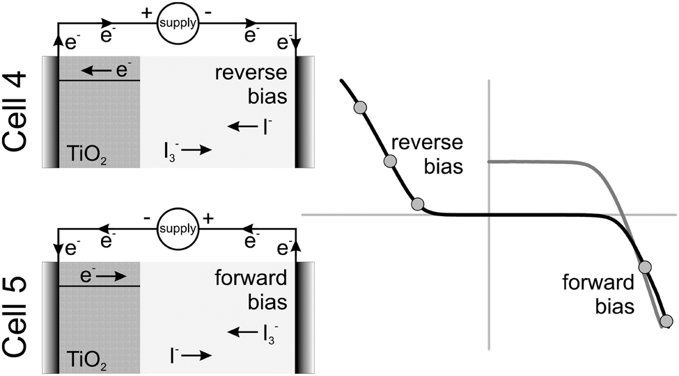 | ||
| Fig. 4 The flow of the electrons in the DSSCs in the dark under reverse (top left) or forward bias current (bottom left). The graph (right) shows both a typical dark I–V characteristic of the DSSC and the values of the reverse and forward bias currents applied to the cells 4 and 5, respectively. | ||
The reverse bias was applied to cell 4. In this case the flow of the electrons and ions is the same as under normal operation under illumination, i.e. the applied current is positive. Since the current was applied in the dark, the voltage on the cell was negative. This condition would generally occur in a shaded cell that is connected in series with others in a PV module. Alternatively, the electrons and ions flow in the opposite direction when a forward bias current was applied, i.e. the applied current is negative, while the voltage on the cell becomes positive (Fig. 4). A similar situation will occur in a shaded cell connected in parallel with the others in a PV module, i.e. the shaded cell would perceive a fixed voltage from the illuminated cells.
Fig. 5 shows EL images of cells 4 and 5 measured after the following: fabrication (phase a), after 1st resting period, after applying reverse or forward current treatment, and after heat treatment at 80 °C for 1 h. Table 2 gathers the performance parameters: JSC, VOC, FF and η, measured under STC at equivalent stages. All stages of ageing including the more frequent TI snapshots during reverse or forward current treatment are shown in Fig. S6 in the ESI.† Additionally, a movie is given in the ESI† which demonstrates the accelerated evolution of spatial defects (formation of bubbles and crystal growth) under reverse and forward current treatment.
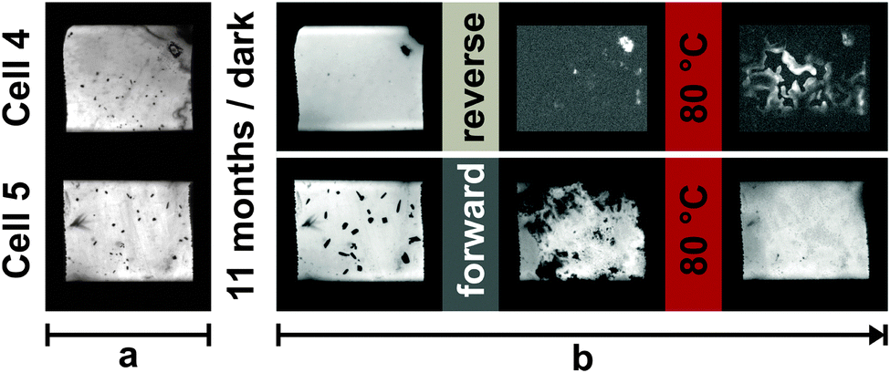 | ||
| Fig. 5 The EL images taken after the fabrication (phase a), after 1st resting period (i.e. before current treatment), after reverse (cell 4) or forward (cell 5) current treatment and finally after the heat treatment at 80 °C for 1 h. All stages of ageing including the more frequent TI snapshots during both reverse and forward current treatment are presented in Fig. S6 in the ESI.† | ||
| Cell | Time | J SC (mA cm−2) | V OC (V) | FF (%) | η (%) |
|---|---|---|---|---|---|
| Cell 4 (reverse) | Fresh | 9.74 | 0.664 | 56.2 | 3.63 |
| 1st resting period | 7.52 | 0.758 | 70.7 | 4.03 | |
| Reverse current treat. | 0.00 | 0.007 | 0.0 | 0.00 | |
| 1 h at 80 °C | 0.08 | 0.254 | 21.2 | 0.01 | |
| Cell 5 (forward) | Fresh | 10.17 | 0.658 | 62.4 | 4.18 |
| 1st resting period | 9.37 | 0.695 | 65.8 | 4.29 | |
| Forward current treat. (1st meas.) | 1.90 | 0.605 | 45.5 | 0.52 | |
| Forward current treat. (12th meas.) | 6.95 | 0.628 | 54.7 | 2.39 | |
| 1 h at 80 °C | 10.64 | 0.630 | 62.1 | 4.16 | |
Reverse current treatment. After the 1st resting period a reverse current (Fig. 4) was applied to the non-illuminated cell 4. After applying a constant current equal to 0.2 × JSC for 5.5 min bubbles appeared after only a few seconds (Fig. 6; for more details see the movie and Fig. S6 in the ESI†). These small bubbles then combined to form a few large bubbles. Applying a reverse current equal to the JSC for 6.66 h resulted in a gradual decrease in bubble size and dye molecules to become detached from the TiO2 surface. Finally, a current equal to 2 × JSC was applied for a further 18 h. Initially a few large bubbles appeared, but soon after the cell became severely damaged. The active area became very inhomogeneous and covered with bright and dark spots moving in the active area/electrolyte. During all three stages when a reverse current was applied the absolute value of the reverse bias voltage increased, i.e. the voltage across the cell became more negative, indicating a likely decrease in the [I3−], which is in agreement with Mastroianni et al.30,31
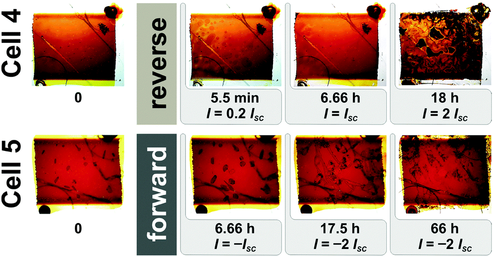 | ||
| Fig. 6 The transmittance images (TI) before and after exposure to reverse (cell 4) or forward current treatment (cell 5). | ||
The formation of bubbles and/or detachment of the dye molecules under reverse bias have already been observed.30–32 Figgemeier et al.32 observed the formation of oxygen and/or hydrogen bubbles when water entered a cell while Mastroianni et al.30,31 observed a rapid degradation of DSSCs accompanied by dye detachment, evolution of gas inside the cell, and cell breakdown after applying voltages more negative than −1.65 V. They found that the bubbles have an electrolysis-dependent origin and form at the Pt/electrolyte interface where I2 reacts with residual H2O, which in turn creates hydrogen bubbles.30 They also observed that long bias stresses retain the dye in its oxidized state for a prolonged period of time making it more probable that it can suffer destructive reactions and irreversible degradations involving ligand oxidation, thiocyanate (SCN−) detachment, and binding between SCN− and impurities (such as H2O/OH−) or I−/I3− ions.30
Our results show that an applied reverse current significantly reduces cell performance. All performance parameters of cell 4 became virtually zero (Table 2). Such severe damage was also observed using EL which revealed that cell 4 was inactive (Fig. 5). After the reverse bias current treatment, cell 4 was then heated at 80 °C for 1 h. The virtual TI homogeneity of the cell (Fig. 6 and Fig. S6, ESI†), the intensity of the EL response (Fig. 5), and the performance parameters (Table 2) improved but major defects remained such that heat treatment did not have a restorative effect. The cell was then rested for a 2nd resting period. Measurements were taken before and after an additional heat treatment at 80 °C for 8 h. Results show that cell performance parameters had improved during the 2nd resting period and partly during a further heat treatment but overall cell performance remained low (JSC = 0.11 mA cm−2, VOC = 0.434 V, FF = 33.7% and η = 0.02%). Both defects and inhomogeneities were clearly observable by TI and EL (not shown here).
Forward current treatment. A forward bias current treatment was applied to the non-illuminated cell 5 after the 1st resting period (Fig. 5 and 6). First, a current equal to −JSC was applied to the cell for 6.66 h. During this period crystal growth was extremely fast when the current was applied and the area covered by the crystals almost doubled in size after the first 6.66 h (Fig. 6; see also movie and Fig. S6 in the ESI†). We then applied a current equal to −2 × JSC for 17.5 h. The crystals rapidly grew out in all directions in a dendritic pattern. The colour of the crystals also became brighter. Finally the same current was applied for a further 66 h during which a similar phenomenon, albeit more gradual one, was observed. Then at the 59th h a strong collapse of the electrolyte occurred introducing a major inhomogeneity in the cell. During all stages the value of the forward bias voltage also increased, indicative of a reduction in the [I3−].
The breakdown of the cell that occurred after the forward bias current treatment was also observed by EL (Fig. 5). The active area of the cell also became inhomogeneous and covered with large inactive dark spots. In addition, performance parameters and especially the JSC decreased significantly (Table 2), i.e., η was reduced from 4.29% to 0.52% (88% relatively). Repeating I–V measurements gradually increased cell performance, which stabilized after 12 measurements. The value of η (2.39%) remained below 4.29% measured before applying a forward bias current.
After heating cell 5 at 80 °C for 1 h the cell’s active area became homogeneous (Fig. 5), which implies an extensive restoration of cell performance. The JSC reached its highest value while VOC remained below its initial value (Table 2). Interestingly FF and η were practically the same as initially measured, which demonstrates the restorative effect of heat treatment on the performance of the DSSCs. After the 2nd resting period (not shown here) several small crystals had reappeared, which was also observed with TI and EL. The I–V measurements reveal a decrease in JSC while FF and VOC increased (JSC = 9.87 mA cm−2, VOC = 0.655 V, FF = 66.0%). Surprisingly, η reached 4.27% equalling the maximal value measured prior to applying a forward bias current. After heating cell 5 at 80 °C for a further 8 h (not shown here) the crystals dissolved and JSC increased and VOC decreased due to the higher [I3−]. In addition, FF decreased due to increasing serial resistance losses while η remained the same (JSC = 10.33 mA cm−2, VOC = 0.630 V, FF = 65.6%, η = 4.27%).
4 Conclusions
Electroluminescent imaging and TI were successfully used to track the development of iodide containing crystals in ionic liquid based DSSCs with a I3−/I− redox couple that had been (i) stored in the dark, (ii) heat treated at 60 °C or 80 °C since cell temperature outdoors could easily exceed 60 °C, and (iii) exposed to reverse and forward current treatment in the dark to simulate a shaded cell connected in either series or parallel in a PV module. This study confirms that crystal growth occurs in cells stored in the dark for a significant period of time (9–11 months) and that heat treatment at both 60 °C and 80 °C leads to their dissolution.I–V characterization confirmed that the presence of these crystals significantly influences the performance of the DSSCs. The formation/growth of the crystals is associated with a decrease in [I3−] in the electrolyte which causes a decrease in JSC and an increase in VOC, while the opposite behaviour is observed when the crystals dissolved. Interestingly, the crystals do not reappear even after a resting period of 9 months if they had been completely removed by heat treatment. Our observations support the theory that in the electrolyte the additive N-methylbenzimidazole reacts with iodine forming iodine containing crystals such as the (MBI)6(MBI-H+)2(I−)(I3−) complex.
In general, repeated I–V measurements under standard test conditions do not influence crystal growth. Applying a reverse current to the DSSC leads to the rapid formation of H2 bubbles and detachment of the dye molecules from the TiO2 surface which results in the irreversible breakdown of the cell. When a forward current is applied crystal growth is rapid and cell performance decreases by 88%. In this case repeated I–V measurements and especially a heat treatment at 80 °C for 1 h can restore cell performance showing a strong restorative effect of the heat treatment although the visible defects and strongly inhomogeneous active area caused a significant loss of the cell's performance in first place. From the findings of our study heat treating DSSCs at 80 °C should be used to either initially stabilize or restore an I3−/I− redox couple based electrolyte and in turn cell performance.
Acknowledgements
The authors would like to thank Marko Jankovec for his support in characterization of dye-sensitized solar cells. Mateja Hočevar is acknowledged for TiO2 paste and electrolyte preparation and Jože Stepan for his help in fabricating the cells. Dr David Heath is gratefully acknowledged for all his advices and for reading the manuscript. M.B. would like to acknowledge the Slovenian Research Agency (contract number Z2-4189-1538) for funding this study. The work was also partially funded by the Slovenian Research Agency under the P2-0197 program.References
- B. O'Regan and M. Grätzel, Nature, 1991, 353, 737–740 CrossRef CAS.
- M. Grätzel and K. Kalyanasundaram, Curr. Sci., 1994, 66, 706–714 Search PubMed.
- A. G. Kontos, T. Stergiopoulos, V. Likodimos, D. Milliken, H. Desilvesto, G. Tulloch and P. Falaras, J. Phys. Chem. C, 2013, 117, 8636–8646 CAS.
- N. Jiang, T. Sumitomo, T. Lee, A. Pellaroque, O. Bellon, D. Milliken and H. Desilvestro, Sol. Energy Mater. Sol. Cells, 2013, 119, 36–50 CrossRef CAS PubMed.
- M. I. Asghar, K. Miettunen, J. Halme, P. Vahermaa, M. Toivola, K. Aitola and P. Lund, Energy Environ. Sci., 2010, 3, 418–426 CAS.
- R. Harikisun and H. Desilvestro, Sol. Energy, 2011, 85, 1179–1188 CrossRef CAS PubMed.
- L. Ciammaruchi, S. Penna, A. Reale, T. M. Brown and A. Di Carlo, Microelectron. Reliab., 2013, 53, 279–281 CrossRef CAS PubMed.
- S. Mastroianni, A. Lanuti, S. Penna, A. Reale, T. M. Brown, A. Di Carlo and F. Decker, ChemPhysChem, 2012, 13, 2925–2936 CrossRef CAS PubMed.
- A. Listorti, C. Creager, P. Sommeling, J. Kroon, E. Palomares, A. Fornelli, B. Breen, P. R. F. Barnes, J. R. Durrant, C. Lawa and B. O'Regan, Energy Environ. Sci., 2011, 4, 3494–3501 CAS.
- K. Zhu, S.-R. Jang and A. J. Frank, Energy Environ. Sci., 2012, 5, 9492–9495 CAS.
- M. Berginc, U. Opara Krašovec and M. Topič, Sol. Energy Mater. Sol. Cells, 2014, 120, 491–499 CrossRef CAS PubMed.
- H. Pettersson, T. Gruszecki, C. Schnetz, M. Streit, Y. Xu, L. Sun, M. Gorlov, L. Kloo, G. Boschloo, L. Häggman and A. Hagfeldt, Prog. Photovoltaics, 2010, 18, 340–345 Search PubMed.
- S. H. Seo, S. Y. Kim, B.-K. Koo, S.-I. Cha and D. Y. Lee, Langmuir, 2010, 26, 10341–10346 CrossRef CAS PubMed.
- K. Miettunen, X. Ruan, T. Saukkonen, J. Halme, M. Toivola, H. Guangsheng and P. Lund, J. Electrochem. Soc., 2010, 157, B814–B819 CrossRef CAS PubMed.
- M. Carnie, D. Bryant, T. Watson and D. Worsley, Int. J. Photoenergy, 2012, 2012, 1–8 Search PubMed.
- N. Kato, Y. Takeda, K. Higuchi, A. Takeichi, E. Sudo, H. Tanaka, T. Motohiro, T. Sano and T. Toyoda, Sol. Energy Mater. Sol. Cells, 2009, 93, 893–897 CrossRef CAS PubMed.
- G. Xue, Y. Guo, T. Yu, J. Guan, X. Yu, J. Zhang, J. Liu and Z. Zou, Int. J. Electrochem. Sci., 2012, 7, 1496–1511 CAS.
- C.-H. Lee, K.-M. Lee, Y.-L. Tung and J.-M. Wu, J. Electrochem. Soc., 2012, 159, B430–B433 CrossRef CAS PubMed.
- M. Toivola, L. Peltokorpi, J. Halme and P. Lund, Sol. Energy Mater. Sol. Cells, 2007, 91, 1733–1742 CrossRef CAS PubMed.
- P. M. Sommeling, M. Späth, H. J. P. Smit, N. J. Bakker and J. M. Kroon, J. Photochem. Photobiol., A, 2004, 164, 137–144 CrossRef CAS PubMed.
- A. Hinsch, J. M. Kroon, R. Kern, I. Uhlendorf, J. Holzbock, A. Mayer and J. Ferber, Prog. Photovoltaics, 2001, 9, 425–438 CAS.
- M.-J. Kim and N.-G. Park, Appl. Surf. Sci., 2012, 258, 8915–8918 CrossRef CAS PubMed.
- A. Fischer, H. Pettersson, A. Hagfeldt, G. Boschloo, L. Kloo and M. Gorlov, Sol. Energy Mater. Sol. Cells, 2007, 91, 1062–1065 CrossRef CAS PubMed.
- M. Bokalič, U. Opara Krašovec and M. Topič, Prog. Photovoltaics, 2013, 21, 1176–1180 Search PubMed.
- U. Opara Krašovec, M. Bokalič and M. Topič, Sol. Energy Mater. Sol. Cells, 2013, 117, 67–72 CrossRef PubMed.
- A. Hinsch, H. Brandt, W. Veurman, S. Hemming, M. Nittel, U. Würfel, P. Putyra, C. Lang-Koetz, M. Stabe, S. Beucker and K. Fichter, Sol. Energy Mater. Sol. Cells, 2009, 93, 820–824 CrossRef CAS PubMed.
- U. Opara Krašovec, M. Berginc, M. Hočevar and M. Topič, Sol. Energy Mater. Sol. Cells, 2009, 93, 379–381 CrossRef PubMed.
- D. Kuang, P. Wang, S. Ito, S. M. Zakeeruddin and M. Grätzel, J. Am. Chem. Soc., 2006, 128, 7732–7733 CrossRef CAS PubMed.
- M. Adachi, M. Sakamoto, J. Jiu, Y. Ogata and S. Isoda, J. Phys. Chem. B, 2006, 110, 13872 CrossRef CAS PubMed.
- S. Mastroianni, A. Lembo, T. M. Brown, A. Reale and A. Di Carlo, ChemPhysChem, 2012, 13, 2964–2975 CrossRef CAS PubMed.
- S. Mastroianni, A. Lanuti, T. M. Brown, R. Argazzi, S. Caramori, A. Reale and A. Di Carlo, Appl. Phys. Lett., 2012, 101, 123302 CrossRef PubMed.
- E. Figgemeier and A. Hagfeldt, Int. J. Photoenergy, 2004, 6, 127–140 CrossRef CAS.
Footnote |
| † Electronic supplementary information (ESI) available. See DOI: 10.1039/c4cp01463d |
| This journal is © the Owner Societies 2014 |