 Open Access Article
 This Open Access Article is licensed under a
 Creative Commons Attribution 3.0 Unported Licence
Non-innocent side-chains with dipole moments in organic solar cells improve charge separation
Hilde D.
de Gier
a,
Ria
Broer
a and
Remco W. A.
Havenith
*ab
aTheoretical Chemistry, Zernike Institute for Advanced Materials, University of Groningen, Nijenborgh 4, 9747 AG Groningen, The Netherlands. E-mail: r.w.a.havenith@rug.nl
bGhent Quantum Chemistry Group, Department of Inorganic and Physical Chemistry, Ghent University, Krijgslaan 281 (S3), B-9000 Gent, Belgium
First published on 6th May 2014
Abstract
Providing sustainable energy is one of the biggest challenges nowadays. An attractive answer is the use of organic solar cells to capture solar energy. Recently a promising route to increase their efficiency has been suggested: developing new organic materials with a high dielectric constant. This solution focuses on lowering the coulomb attraction between electrons and holes, thereby increasing the yield of free charges. In here, we demonstrate from a theoretical point of view that incorporation of dipole moments in organic materials indeed lowers the coulomb attraction. A combination of molecular dynamics simulations for modelling the blend and ab initio quantum chemical calculations to study specific regions was performed. This approach gives predictive insight in the suitability of new materials for application in organic solar cells. In addition to all requirements that make conjugated polymers suitable for application in organic solar cells, this study demonstrates the importance of large dipole moments in polymer side-chains.
1. Introduction
One of the biggest challenges nowadays is to generate sustainable energy. Solar energy is an attractive solution for which effective and low-cost solar cells are needed. Because of their high efficiency (∼20–25%1), currently silicon solar cells are the most conventional ones. However, their high manufacturing costs are an important disadvantage. An attractive low-cost alternative is the solution-processed organic solar cell, which has several advantages compared to the silicon ones: they can be produced from cheap raw materials and they are light and flexible. Unfortunately, the efficiency of organic solar cells is still quite low (∼10%1).Currently, the best-performing single-junction organic solar cell consists of a three-dimensional (bulk) heterojunction composed of a hole-conducting (donor) and an electron-conducting (acceptor) material2 (Fig. 1). The donor typically is a conjugated polymer that absorbs most of the light and the acceptor is a fullerene derivative. After light absorption, excitons (i.e., bound electron–hole pairs) are formed that diffuse towards the donor–acceptor interface. Due to the bulk heterojunction, almost all excitons reach the interface. Subsequently, electrons transfer from donors to acceptors with a quantum efficiency approaching unity.3,4 Collection of charges takes place at the different electrodes of the solar cell.
 | ||
| Fig. 1 Schematic representation of a bulk heterojunction organic solar cell. The active layer is composed of polymers with side-chains and PCBM molecules and sandwiched between electrodes. | ||
To recognise why the efficiency of organic solar cells is nevertheless low, we need to understand in detail its working mechanism describing the processes that take place at the donor–acceptor interface (Fig. 2). Most models visualize the main problem of organic solar cells by making use of a charge-transfer (CT) state, where the electron at the acceptor and the hole at the donor are coulombically bound.5 This state serves as an intermediate between the initial excited and the final charge-separated (CS) state, where the electron and hole are no longer coulombically bound.5
 | ||
| Fig. 2 Electronic state diagram of the working mechanism of an organic solar cell. The blue arrows show the basic steps in an organic solar cell after light absorption to create free charges when hot CT states (CTn) are involved. The green arrows show the energy difference defined as the CT exciton binding energy and the CS state energy, which is the energy difference between the ionisation potential (IP) of the donor (D) and the electron affinity (EA) of the acceptor (A). Vibrational energy levels within the CT manifold are depicted in grey. (D+˙ = radical cation of donor; A−˙ = radical anion of acceptor.) | ||
In organic solar cells a problem arises because often the lowest CT state (CT1) of the CT manifold lies lower in energy than the CS state, which limits the generation of free charges (Fig. 2). The energy difference is called the charge-transfer (CT) exciton binding energy and is estimated to be ∼0.3–0.5 eV.6,7 In literature several mechanisms have been proposed to explain the generation of free charges in such a situation, like the involvement of hot CT states (CTn)5,8,9 (Fig. 2). In some of the explanations changes in entropy resulting from electronic degeneracy are not considered.9 However, an entropy contribution is expected to stabilise the CS state relative to the CT state.9 Such a stabilisation is also expected from the presence of interfacial dipoles, favourable polymer chain conformations and morphological effects.10
Recently, a new route to lower the energy difference between the CT and CS states and thereby improving the performance of organic solar cells has been suggested: developing new molecular donor/acceptor materials with a high dielectric constant.11 To this end, dipole moments are incorporated in the materials. Until now, the use of dipole moments in order to stabilise free charges has not been applied to organic solar cells. In this work, we focus on answering the research question whether or not incorporating dipole moments in polymer side-chains lowers the coulomb attraction between positive and negative charges. Our results show that indeed side-chains are electronically not innocent spectators (they may also influence the morphology), but that they exert electronic effects on the CS state. This insight will lead to new design guides for donor/acceptor materials that show an increased yield of free charges.
To answer the research question from a theoretical point of view, we studied the influence of the molecular environment on the electronic structure of a polymer-[6,6]-phenyl-C61-butyric acid methyl ester (PCBM) model system. Usually nanoscale morphologies of polymer:PCBM blends are modelled using multiscale coarse-grained molecular dynamics (MD) simulations.12,13 Examples of quantum chemical (QC) studies of polymer:PCBM blends involve density functional theory (DFT) studies on one PCBM molecule in the vicinity of a short polymer chain.14 Here we go one step further by doing a so-called MD/QC approach. After having performed MD simulations, we investigated specific regions of the blend using ab initio QC calculations. A hybrid quantum mechanical and molecular mechanics (QM/MM) model, namely the discrete reaction field (DRF) method,15–17 was used to treat the embedding molecules classically with point charges and polarisabilities while the central complex was treated quantum mechanically.
Our model system consisted of one donor–acceptor co-monomer (1 or 2) and one PCBM molecule (3) in a representative configuration, embedded in only monomers (1, 2 or 4) (Fig. 3). This particular co-monomer structure was investigated because of computational18,19 and experimental18,19 studies done on the influence of replacing the bridging carbon atom in the cyclopentadithiophene unit by a silicon atom on the performance of organic solar cells. The results showed that in the Si case a more crystalline material was formed,18 and no evidence was found for the formation of a long-lived charge-transfer complex in blends of this polymer with PCBM.19
 | ||
| Fig. 3 Structures of the monomers and PCBM used in this study. Structure 1 contains side-chains with a small dipole moment (1.6 Debye), 2 with a large dipole moment (7.3 Debye) and 4 without dipole moment; 4 was therefore used as a reference monomer. Total dipole moment of monomer 1: 2.7 Debye, of 2: 8.2 Debye and of 4: 1.9 Debye. | ||
We chose to vary the dipole moment in the polymer side-chain: one has a small (1.6 Debye, 1) and one has a large (7.3 Debye, 2) dipole moment. Monomer 4 was used as a reference to determine the environmental effect of monomers that have side-chains without dipole moments. By exclusion of the PCBM molecules from the molecular environment, the stabilisation of PCBM caused by other PCBM molecules was excluded, but this only removes a uniform stabilisation effect.
We used (time-dependent) (TD)-DFT with the density functional Becke half and half (BHandH)20 to calculate the electronic state diagram of the complexes 1-3 and 2-3 with and without environment. Its application in combination with the BHandH functional to study these systems and the environmental effect is justified for different reasons: similar (TD)-DFT studies on a P3HT:PCBM complex showed that functionals especially designed for CT states do not give appreciably different excitation energies for these systems compared to regular functionals.14 More extensive work done on evaluating the performance of DFT functionals for CT states showed good behaviour for the functional of our choice,21 and lastly, the effect of the environment shows hardly any variation with the choice of functional (see also the Computational details section).
For both complexes 1-3 and 2-3 three different electronic state diagrams were obtained: e.g., 1-3 in vacuum, 1-3 embedded in 4 and 1-3 embedded in 1. Every electronic state diagram with environment was obtained for only one configuration of embedding molecules. During one MD simulation, all generated solvent configurations were correlated. Based on the timescales of these processes,22 we expect only moderate changes in the configuration of embedding molecules. Calculating many solvent configurations would not change the observed trends, but would only result in small deviations in excited state energies. Therefore our choice for a correlated description and calculating only one particular configuration is sufficient for the question we aim to answer.
2. Computational details
To determine a representative donor–acceptor configuration, we performed dispersion-corrected DFT (DFT-D23) (6-31G**/B3LYP24) geometry optimisations (GAMESS-UK25) on four initial configurations of a central donor–acceptor complex of one donor–acceptor co-monomer with two different side-chains (–C7H14F (1), –CH3 (4)) and one PCBM molecule (Fig. 5). The B3LYP functional was chosen for the geometry optimisations, because of its suitability in this respect.26 The structures represent possible configurations at the donor–acceptor interface. Configuration c, where the acceptor part of the co-monomer was positioned above PCBM, is the lowest in energy (Table 1). Subsequently, neutral, cationic and anionic geometry optimisations were performed for the two donor–acceptor complexes 1-3 and 2-3 in configuration c. The use of only a co-monomer instead of a polymer is justified here, because excitation energies, ionisation potentials and electron affinities of related co-monomers show the same trends as for their oligomers.27The central donor–acceptor complex was embedded in a molecular environment of only monomers. Configurations of these embedding molecules were obtained by doing MD simulations. In these simulations (Tinker28), the NVT ensemble using a Berendsen thermostat with coupling constant of 0.1 ps was employed. The system temperature was set at 298 K; all the boundaries were periodic; Verlet integration method was used; Ewald summation – with real-space cutoff of 7.0 Å – was turned on during computation of electrostatic interactions; cutoff distance was 12 Å for van der Waals potential energy interactions; cutoff distance for all non-bonded potential energy interactions was 14 Å; convergence criterion was 0.01 Debye for computation of self-consistent dipoles; the time step was 1 fs; the MM3 simulation package29 (additional parameters were added when required for the studied systems) was employed. Firstly, a MD simulation of 10 ps was performed for solely the environment (cubic box with a-axis ∼40 Å). Secondly, one of the final snapshots of this simulation was chosen as start for the simulation of the central donor–acceptor complex in environment. The simulation time of this MD simulation was 200 ps. The atoms of the central donor–acceptor complex were set inactive (i.e., not allowed to move) during the simulation. The density of the complete system is for 1-3 in 4: 1.4 g ml−1; for 1-3 in 1: 1.3 g ml−1; for 2-3 in 4: 1.4 g ml−1; for 2-3 in 2: 1.4 g ml−1.
The snapshots for our calculations were selected from the last 195–200 ps MD snapshots based on the smallest distance between an atom belonging to the central donor–acceptor complex and an atom belonging to the embedding molecules. If this distance was smaller than 1.8 Å, the particular snapshot was rejected. A too small distance between the QM and MM parts invalidates the embedding model.
Single-point (TD)-DFT (DZP/BHandH) calculations (BHandH: 50% HF exchange, 50% LDA exchange and 100% LYP correlation in ADF30,31) for the neutral, cationic and anionic complexes were performed, both with and without environment in order to obtain the electronic state diagram as presented in Fig. 2. The BHandH functional was chosen, because this functional is more suitable for calculating excited states than the B3LYP functional, especially in the case of states with charge-transfer character.21 A change in basis set from Gaussian-type 6-31G** used for geometry optimisations to Slater-type DZP used for single-point (TD)-DFT calculations, is inevitable due to the change from GAMESS-UK to ADF. A hybrid QM/MM model, namely the DRF method,15–17 was used to treat the embedding molecules classically with point charges and polarisabilities and the central complex quantum mechanically. TD-DFT was used to obtain the excited state with the highest oscillator strength (labelled (S*)vert) which has – in all cases – the largest weight of the HOMO → LUMO + 3 one-electron transition. The HOMO is located at the donor part of the co-monomer and the LUMO + 3 at the acceptor part of the co-monomer, so (S*)vert corresponds to an excitation located at the co-monomer. The CT state of the central donor–acceptor complex was also obtained from the TD-DFT calculations (i.e., the excited state with the largest charge-transfer character from donor to acceptor, labelled (CT)vert). The amount of charge-transfer character was estimated from the weight of the HOMO → LUMO one-electron transition to a given excitation: the HOMO is located at the donor molecule (co-monomer) and the LUMO at the acceptor molecule (PCBM). The excitation with the largest weight of this HOMO → LUMO transition was labelled the CT state. DFT energies for the cationic and anionic complex were used to determine the final CS state energy as the difference between IP and EA of the central donor–acceptor complex.
To investigate the stabilisation of the CS state by dipole alignment, two types of MD simulations were performed: one with a neutral donor–acceptor complex and one with net charges present at the central complex. In the first case the dipole moments are oriented randomly (we call this the CS state without dipole alignment). In the second case the dipole moments are allowed to align favourably according to the net charges (we call this the CS state with dipole alignment). Net charges were obtained by performing a dipole preserving analysis (DPA) using DFT (6-31G**/B3LYP) for the neutral, cationic and anionic complexes (GAMESS-UK). For all cationic complexes the positive charge was mainly located on the monomer and for all anionic complexes the negative charge on the PCBM. Subsequently, three MD simulations of 50 ps were performed for these complexes with DPA charges present at the central complex. In this way, embedding configurations were obtained where a rearrangement of the embedding molecules was possible in response to the DPA charges.
Dipole moments of the polymer side-chains and monomers were calculated using DFT (6-31G**/B3LYP) (GAMESS-UK).
For the analysis of the difference in quantum mechanical/classical interaction energy between the (cationic and anionic) central complex 2-3 with either environment 2 or 4 (with and without dipole alignment), the quantum mechanical part was replaced by two point charges: one located at the centre-of-mass of 2 with its corresponding DPA charge (for the cationic or anionic complex) and the other one located at the centre-of-mass of 3 with its corresponding DPA charge (for the cationic or anionic complex) (GAMESS-UK).
To analyse the change in orientation of the embedding molecules with respect to the relaxed cationic complex 2-3 when allowing dipole moment alignment, the distance r between the carbon atoms of the embedding molecules 2 to which the NH2 group is attached and the centre-of-mass of the co-monomer 2 of 2-3, and the angle α between NO2, NH2 and the centre-of-mass of the co-monomer 2 of 2-3 (Fig. 4) were probed. The differences in distances r and angles α were calculated for every side-chain between the snapshots with and without a net positive charge at 2-3. If dipoles align towards the positive charge of the cationic complex, a decrease in the distances r of dipoles and their angles α would be observed. The snapshots that were analysed in this way were the same as used to determine the IP of the central cationic complex 2-3 with and without dipole alignment.
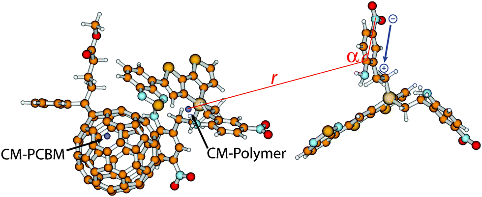 | ||
| Fig. 4 Schematic representation of the analysis of the change in distance r and angle α, both with respect to the centre-of-mass (CM) of the co-monomer, of every dipole in environment 2 as a consequence of a positive charge present at the relaxed cationic complex of 2-3. In blue, the local dipole moment of the side chain is indicated. | ||
The choice of the BHandH functional was based on a comparison between polarizable continuum model32 (PCM)-DFT calculations using several functionals and second-order approximate coupled-cluster singles and doubles (CC2) calculations on a small donor–acceptor complex (parabenzoquinone-tetrathiafulvalene). This study made clear that BHandH is closest to the CC2 result and thus provides a reasonable description of the states we studied. Furthermore, the effect of the environment turned out not to be dependent on the choice of functional. As a second check, we compared the results of TD-DFT calculations using the BHandH functional with the ones of TD-DFT calculations using the CAMB3LYP functional,33 which is known to be a reasonably good functional for charge-transfer states.33,34 For the states of interest, DZP/BHandH calculations result in (CT)vert = 2.3 eV and (S*)vert = 2.8 eV, and DZP/CAMYB3LYP35 calculations result in (CT)vert = 2.2 eV and (S*)vert = 2.8 eV. Based on these results, we conclude that considerable agreement is found between the two functionals.
3. Results and discussion
3.1 Geometry of the central donor–acceptor complex
Four initial configurations of a central donor–acceptor complex of one co-monomer and one PCBM molecule were generated and optimised (Fig. 5). Fig. 5 only shows the obtained geometries for co-monomer 1. For this co-monomer, geometry optimisation of configuration d – where the donor part of the co-monomer initially was positioned above PCBM – led to configuration c – where the acceptor part of the co-monomer was positioned above PCBM. It appeared that for both side-chains the configuration where the acceptor part of the co-monomer was positioned above PCBM (configuration c) is the lowest in energy (Table 1), and it was therefore selected for the study of CT states.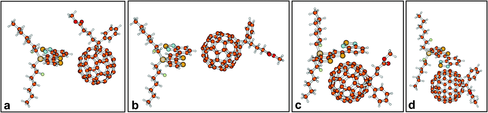 | ||
| Fig. 5 Four optimised configurations of the central donor–acceptor complex (1-3). For co-monomer 1, configurations c and d are energetically and geometrically almost identical. | ||
3.2 Results for the donor–acceptor complex 1-3
The calculated electronic state diagrams obtained with and without environment are shown in Fig. 6a–c. (S*)vert corresponds to the excited state with the largest oscillator strength, (CT)vert to the excited state with the largest charge-transfer character from 1 to 3, and (CS)vert to the charge-separated state, all three at the ground state geometry of the complex. (CS)relaxed corresponds to the charge-separated state determined with relaxed cationic and anionic complex geometries. (S*)vert is the 13th excited state in vacuum and in 1, and the 10th in 4 (weight of HOMO → LUMO + 3 transition to (S*)vert for 1-3 in vacuum: 0.61; for 1-3 in 4: 0.77; for 1-3 in 1: 0.78). In all three cases (CT)vert is the lowest excited state (weight of HOMO → LUMO transition to (CT)vert for 1-3 in vacuum: 0.67; for 1-3 in 4: 0.83; for 1-3 in 1: 0.60). From Fig. 6 it follows that for (CS)vert a significant stabilising effect of ∼1 eV from 4.1 eV in vacuum (Fig. 6a) to 2.9 eV in 4 (Fig. 6b) or 3.0 eV in 1 (Fig. 6c) is found, caused by the environment. In all three cases, geometry relaxation of the CS state results in an extra stabilisation of ∼0.1 eV. This effect originates predominantly from relaxation of the cation, which results in a lower IP (Table 2). (S*)vert nor (CT)vert are significantly stabilised by the molecular environment. Thus, our results show a reduction in the CT exciton binding energy of ∼1 eV (Table 2) due to the environment. | ||
| Fig. 6 Electronic state diagrams for the studied donor–acceptor complexes. Diagram (a) shows the results for 1-3 without environment, (b) for 1-3 in 4, (c) for 1-3 in 1, (d) for 2-3 without environment, (e) for 2-3 in 4 and (f) for 2-3 in 2. Black lines correspond to vertical excitations, i.e., energies obtained at the ground state geometry of 1(2)-3. Red and blue lines correspond to energies obtained at relaxed cationic and anionic geometries of 1(2)-3. The red line corresponds to the CS state without dipole alignment and the blue line to the CS state with dipole alignment. | ||
| System | (CS)vert | (CS)relaxed without dip. alignment | (CS)relaxed with dip. alignm. | CT exciton binding energy w.r.t. (CS)relaxed | ||||
|---|---|---|---|---|---|---|---|---|
| IP | EA | IP | EA | IP | EA | Without dip. alignm. | With dip. alignm. | |
| 1-3 in vac. | 6.8 | 2.7 | 6.6 | 2.7 | — | — | 1.6 | — |
| 1-3 in 4 | 6.4 | 3.5 | 6.2 | 3.4 | 6.1 | 3.6 | 0.6 | 0.3 |
| 1-3 in 1 | 6.3 | 3.3 | 6.1 | 3.2 | 6.0 | 3.3 | 0.6 | 0.4 |
| 2-3 in vac. | 7.4 | 3.1 | 7.1 | 3.0 | — | — | 1.4 | — |
| 2-3 in 4 | 6.6 | 3.4 | 6.3 | 3.2 | 6.3 | 3.4 | 0.5 | 0.3 |
| 2-3 in 2 | 6.9 | 3.6 | 6.3 | 3.5 | 5.8 | 3.8 | 0.2 | −0.6 |
A comparison of the electronic state diagrams obtained with environment (Fig. 6b with c) shows no significant difference. The energies of all relevant states are quite similar. Dipole alignment, which again mainly affects the IP (Table 2), results in a further stabilisation of 1-3 in both environments of ∼0.3 eV. This similar effect of dipole alignment in the case of environment 1 compared to the reference environment 4, is in line with the similar dipole moments of both embedding molecules.
Our results for 1-3 in 4 are in line with experimental results18,19 reported for a co-monomer that differs only in side-chain showing no evidence for the formation of a long-lived charge-transfer complex when blended with PCBM. The calculated CT exciton binding energy of ∼0.3 eV can possibly be overcome, because of the reported high crystallinity and improved charge transport properties of the corresponding polymer.
3.3 Results for the donor–acceptor complex 2-3
We first focus again on the calculated electronic state diagrams obtained with environment (Fig. 6e and f) and compare these with the one obtained without environment (Fig. 6d). The states are labelled in the same way as in Fig. 6a–c. (S*)vert is the 16th excited state in vacuum, the 13th in 4 and the 18th in 2 (weight of HOMO → LUMO + 3 transition for 2-3 in vacuum: 0.53; for 2-3 in 4: 0.84; for 2-3 in 2: 0.40). In vacuum (CT)vert is the 7th excited state, in 4 and 2 it is the 6th excited state (weight of HOMO → LUMO transition for 2-3 in vacuum: 0.55; for 2-3 in 4: 0.70; for 2-3 in 2: 0.80). In all three cases, the lowest excited state energy is ∼2.3 eV, which corresponds to a PCBM-excitation, like all other excited states below (CT)vert. For (CS)vert again a significant stabilising effect of ∼1 eV is found (from 4.3 eV (Fig. 6d) to 3.2 eV (Fig. 6e) and 3.3 eV (Fig. 6f)) due to the environment. For 2-3 in vacuum and in 4, geometry relaxation leads to a stabilising effect of ∼0.1 eV originating predominantly from relaxation of the cation; this effect is larger (∼0.5 eV) for 2-3 in 2 (Table 2). (S*)vert nor (CT)vert are significantly stabilised by the molecular environment. From these data, where only stabilisation, caused by the environment, and geometry relaxation are considered, a similar reduction in the CT exciton binding energy of ∼1 eV is found for both 2-3 in 4 and in 2 (Table 2).However, inclusion of dipole alignment results in an extra stabilisation, which is significantly larger in the case of environment 2 (Fig. 6e and f). For the reference environment 4 dipole alignment results in an extra stabilisation of ∼0.2 eV (Fig. 6e: from 3.1 eV to 2.9 eV). For environment 2 dipole alignment results in an extra stabilisation of ∼0.8 eV (Fig. 6f: from 2.8 eV to 2.0 eV). This stabilising effect is the largest for the cation, resulting in a significant lowering of its IP (Table 2). This effect even results in an electronic state diagram where the CS state (i.e., (CS)relaxed with dipole alignment) is below the CT state (i.e., (CT)vert). Consequently the CT exciton binding energy, as defined previously, becomes negative (∼−0.6 eV, Table 2).
To show that the environment indeed responds to charges on the central complex, the interaction energy was determined between the quantum mechanical (i.e., donor–acceptor complex) and classical part (i.e., environment) for (CS)relaxed of 2-3 embedded in 4 and in 2, with and without dipole alignment (Table 3). For environment 2 with dipole alignment, a stronger interaction of ∼0.2 eV between the quantum and classical part is found, which results from the response of the environment. For environment 4, the interaction energy is the same, regardless of dipole alignment or not.
| System | Quantum mechanical/classical interaction energy of 2-3 in 4 | Quantum mechanical/classical interaction energy of 2-3 in 2 |
|---|---|---|
| Relaxed cation of 2-3 in 4(2) without/with dipole alignment | −0.9/−0.9 | −0.9/−1.1 |
| Relaxed anion of 2-3 in 4(2) without/with dipole alignment | −1.2/−1.2 | −1.0/−1.3 |
To further corroborate the suggestion that several dipoles respond to net charges of cationic and anionic complexes, we performed the following analysis. The changes upon dipole alignment in distances of the dipoles and their angles with respect to the centre-of-mass of the co-monomer and PCBM for either the cationic and anionic optimised geometries, respectively, were calculated. The largest changes in distances and angles are expected for dipoles with respect to the centre-of-mass of the co-monomer in the relaxed cationic complex of 2-3 in 2, since dipole alignment appears to affect mainly the IP (Table 2). The response is expected to be the greatest for closely positioned dipoles.
The result of this analysis for the relaxed cationic complex of 2-3 in 2 is given in Fig. 7. This graph visualises the change in distance (Δr, Å) and angle (Δα, °) of every dipole caused by a positive charge present at the cationic complex, both with respect to the centre-of-mass of the co-monomer (where the majority of the positive charge is located). The different (coloured) cues correspond to a particular dipole that is present in a certain range in distance between the dipole and the centre-of-mass of the co-monomer. Small changes in distance between dipoles and the co-monomer are observed (Table 4). A more careful analysis of Δα (Table 4) clarifies that dipoles closest to the co-monomer (i.e., red dots (●)) show a decrease in their angles in order to align favourably (i.e., –NO2 is directed towards the co-monomer). However this decrease is not very large, which indicates that small changes in dipole orientation already result in a significant charge stabilisation.
 | ||
| Fig. 7 Change in distance (Δr, Å) and angle (Δα, °), both with respect to the centre-of-mass of the co-monomer, of every dipole in environment 2 as a consequence of a positive charge present at the relaxed cationic complex of 2-3. The different (coloured) cues correspond to a particular dipole that is present in a certain range in distance between the dipole and the centre-of-mass of the co-monomer: 0.0–7.6 Å (black ◆), 7.6–15.2 Å (red ●), 15.2–22.8 Å (green ×), 22.8–30.4 Å (dark blue +), 30.4–38.0 Å (light blue △), 38.0–45.6 Å (purple ◇) and 45.6–53.2 Å (yellow +). | ||
| Colour and visual cue corresponding to a particular dipole | Range in distance between a particular dipole and the centre-of-mass of the co-monomer | # Dipoles with Δr > 0 | # Dipoles with Δr < 0 | # Dipoles with Δα > 0 | # Dipoles with Δα < 0 |
|---|---|---|---|---|---|
| Black (◆) | 0.0–7.6 | 0 | 1 | 0 | 1 |
| Red (●) | 7.6–15.2 | 19 | 15 | 9 | 25 |
| Green (×) | 15.2–22.8 | 49 | 40 | 40 | 49 |
| Dark blue (+) | 22.8–30.4 | 54 | 33 | 37 | 50 |
| Light blue (△) | 30.4–38.0 | 12 | 6 | 5 | 13 |
| Purple (◇) | 38.0–45.6 | 1 | 0 | 0 | 1 |
| Yellow (+) | 45.6–53.2 | 0 | 0 | 0 | 0 |
4. Conclusion
This work focuses on a promising route to increase the efficiency of organic solar cells, i.e., by designing new organic materials with a high dielectric constant. It demonstrates from a theoretical point of view that polymer side-chains with dipole moments are electronically not innocent spectators, but that they exert electronic effects that lower the coulomb attraction between electrons and holes, thereby facilitating their charge separation. Until now, the use of dipole moments in order to stabilise charges has not been applied to organic solar cells.These results were obtained by successfully applying a MD/QC approach to investigate the influence of the molecular environment on the electronic structure of a monomer:PCBM complex, thereby bringing the state-of-the-art in this field to the next level. This method is able to give predictive insight in the behaviour of polymers in organic solar cells.
Interesting directions for future research are studies of the flexibility of these side-chains and of the time scales needed for dipole alignment. Considering the typical time scales of photo-physical processes, dipole moments have to rearrange themselves within a few hundred fs.22,36 Another interesting issue that was outside the scope of this work, is the relative rates of various pathways. Strong couplings are possible between certain excited states, which can then act as efficient decay channels.
The results of this work can be generalised to a larger field of applications. In all fields where the generation of free charges from excitons forms a central problem, incorporation of dipole moments in materials could be a solution, on the condition that the dipole moment is sufficiently large and able to rotate modestly.
In addition to all requirements that make conjugated polymers suitable for application in organic solar cells,37–39 this theoretical study demonstrates the importance of large dipole moments in polymer side-chains. Addition of this new requirement could bring the next generation organic solar cells within reach.
Acknowledgements
Prof. dr J. C. Hummelen, prof. dr P. Th. van Duijnen and dr A. H. de Vries of the University of Groningen are thanked for stimulating discussions. R.W.A.H. acknowledges the Zernike Institute for Advanced Materials (“Dieptestrategie” program) for financial support. This work is part of the research programme of the Foundation of Fundamental Research on Matter (FOM), which is part of the Netherlands Organisation for Scientific Research (NWO). This is a publication of the FOM-focus Group ‘Next Generation Organic Photovoltaics’, participating in the Dutch Institute for Fundamental Energy Research (DIFFER). The work was partially completed with computing time at the Dutch National Supercomputer Huygens (SURFsara, SH-213-11).References
- M. A. Green, K. Emery, Y. Hishikawa, W. Warta and E. D. Dunlop, Prog. Photovoltaics, 2013, 21, 1–11 Search PubMed.
- G. Yu, J. Gao, J. C. Hummelen, F. Wudl and A. J. Heeger, Science, 1995, 270, 1789–1791 CAS.
- H. Spanggaard and F. C. Krebs, Sol. Energy Mater. Sol. Cells, 2004, 83, 125–146 CrossRef CAS PubMed.
- C. J. Brabec, N. S. Sariciftci and J. C. Hummelen, Adv. Funct. Mater., 2001, 11, 15–26 CrossRef CAS.
- J.-L. Brédas, J. E. Norton, J. Cornil and V. Coropceanu, Acc. Chem. Res., 2009, 42, 1691–1699 CrossRef PubMed.
- C. Deibel, T. Strobel and V. Dyakonov, Adv. Mater., 2010, 22, 4097–4111 CrossRef CAS PubMed.
- C. Piliego and M. A. Loi, J. Mater. Chem., 2012, 22, 4141–4150 RSC.
- A. A. Bakulin, A. Rao, V. G. Pavelyev, P. H. M. van Loosdrecht, M. S. Pshenichnikov, D. Niedzialek, J. Cornil, D. Beljonne and R. H. Friend, Science, 2012, 335, 1340–1344 CrossRef CAS PubMed.
- T. M. Clarke and J. R. Durrant, Chem. Rev., 2010, 110, 6736–6767 CrossRef CAS PubMed.
- M. C. Scharber, C. Lungenschmied, H.-J. Egelhaaf, G. Matt, M. Bednorz, T. Fromherz, J. Gao, D. Jarzab and M. A. Loi, Energy Environ. Sci., 2011, 4, 5077–5083 CAS.
- L. J. A. Koster, S. E. Shaheen and J. C. Hummelen, Adv. Energy Mater., 2012, 2, 1246–1253 CrossRef CAS.
- C.-K. Lee and C.-W. Pao, J. Phys. Chem. C, 2012, 116, 12455–12461 CAS.
- C.-K. Lee, C.-W. Pao and C.-W. Chu, Energy Environ. Sci., 2011, 4, 4124–4132 CAS.
- T. Liu and A. Troisi, J. Phys. Chem. C, 2010, 115, 2406–2415 Search PubMed.
- P. Th. van Duijnen, M. Swart and L. Jensen, Solvation Effects on Molecules and Biomolecules, Springer, Dordrecht, 2008 Search PubMed.
- P. Th. van Duijnen and A. H. de Vries, Int. J. Quantum Chem., 1996, 60, 1111–1132 CrossRef CAS.
- A. H. de Vries, P. Th. van Duijnen, A. H. Juffer, J. A. C. Rullmann, J. P. Dijkman, H. Merenga and B. T. Thole, J. Comput. Chem., 1995, 16, 37–55 CrossRef CAS.
- A. A. Y. Guilbert, J. M. Frost, T. Agostinelli, E. Pires, S. Lilliu, J. E. Macdonald and J. Nelson, Chem. Mater., 2014, 26, 1226–1233 CrossRef CAS.
- M. C. Scharber, M. Koppe, J. Gao, F. Cordella, M. A. Loi, P. Denk, M. Morana, H.-J. Egelhaaf, K. Forberich, G. Dennler, R. Gaudiana, D. Waller, Z. Zhu, X. Shi and C. J. Brabec, Adv. Mater., 2010, 22, 367–370 CrossRef CAS PubMed.
- A. D. Becke, J. Chem. Phys., 1993, 98, 1372–1377 CrossRef CAS PubMed.
- G. Sini, J. S. Sears and J.-L. Brédas, J. Chem. Theory Comput., 2010, 7, 602–609 CrossRef.
- F. Etzold, I. A. Howard, N. Forler, D. M. Cho, M. Meister, H. Mangold, J. Shu, M. R. Hansen, K. Müllen and F. Laquai, J. Am. Chem. Soc., 2012, 134, 10569–10583 CrossRef CAS PubMed.
- S. Grimme, J. Comput. Chem., 2004, 25, 1463–1473 CrossRef CAS PubMed.
- A. D. Becke, J. Chem. Phys., 1993, 98, 5648–5652 CrossRef CAS PubMed.
- M. F. Guest, I. J. Bush, H. J. J. van Dam, P. Sherwood, J. M. H. Thomas, J. H. van Lenthe, R. W. A. Havenith and J. Kendrick, Mol. Phys., 2005, 103, 719–747 CrossRef CAS.
- K. E. Riley, B. T. Op't Holt and K. M. Merz Jr., J. Chem. Theory Comput., 2007, 3, 407–433 CrossRef CAS PubMed.
- H. D. de Gier, B. J. Rietberg, R. Broer and R. W. A. Havenith, Comput. Theor. Chem, 2014 DOI:10.1016/j.comptc.2014.03.002.
- J. W. Ponder, Tinker – Software Tools for Molecular Design, version 6.0, Washington University, St. Louis, U.S.A., 2011 Search PubMed.
- N. L. Allinger, Y. H. Yuh and J.-H. Lii, J. Am. Chem. Soc., 1989, 111, 8551–8566 CrossRef CAS.
- C. Fonseca Guerra, J. G. Snijders, G. te Velde and E. J. Baerends, Theor. Chem. Acc., 1998, 99, 391–403 Search PubMed.
- G. te Velde, F. M. Bickelhaupt, E. J. Baerends, C. Fonseca Guerra, S. J. A. Gisbergen, J. G. Snijders and T. Ziegler, J. Comput. Chem., 2001, 22, 931–967 CrossRef CAS.
- J. Tomasi, B. Mennucci and R. Cammi, Chem. Rev., 2005, 105, 2999–3093 CrossRef CAS PubMed.
- T. Yanai, D. P. Tew and N. C. Handy, Chem. Phys. Lett., 2004, 393, 51–57 CrossRef CAS PubMed.
- M. J. Peach, P. Benfield, T. Helgaker and D. J. Tozer, J. Chem. Phys., 2008, 128, 044118 CrossRef PubMed.
- M. Seth and T. Ziegler, J. Chem. Theory Comput., 2012, 8, 901–907 CrossRef CAS.
- I.-W. Hwang, C. Soci, D. Moses, Z. Zhu, D. Waller, R. Gaudiana, C. J. Brabec and A. J. Heeger, Adv. Mater., 2007, 19, 2307–2312 CrossRef CAS.
- P.-L. Boudreault, A. Najari and M. Leclerc, Chem. Mater., 2011, 23, 456–469 CrossRef CAS.
- R. Kroon, M. Lenes, J. C. Hummelen, P. W. M. Blom and B. de Boer, Polym. Rev., 2008, 48, 531–582 CrossRef CAS.
- H. J. Son, B. Carsten, I. H. Jung and L. Yu, Energy Environ. Sci., 2012, 5, 8158–8170 CAS.
| This journal is © the Owner Societies 2014 |