 Open Access Article
 This Open Access Article is licensed under a
 Creative Commons Attribution 3.0 Unported Licence
Nanoparticle catalysts for proton exchange membrane fuel cells: can surfactant effects be beneficial for electrocatalysis?
J. E.
Newton
a,
J. A.
Preece
b,
N. V.
Rees
*a and
S. L.
Horswell
*b
aSchool of Chemical Engineering, University of Birmingham, Edgbaston, Birmingham, B15 2TT, UK. E-mail: n.rees@bham.ac.uk
bSchool of Chemistry, University of Birmingham, Edgbaston, Birmingham, B15 2TT, UK. E-mail: s.l.horswell@bham.ac.uk
First published on 7th May 2014
Abstract
Platinum (Pt) nanoparticles were prepared in aqueous dispersion using the non-ionic surfactant nonylphenolethoxylate (NP9) and the cationic surfactant tetradecyltrimethylammonium bromide (TTAB). The surfactants were added to give colloidal stability. Such species are generally considered to block electrochemical active sites and to be undesirable for the oxygen reduction reaction (ORR). However, the procedures used to remove them are likely to cause particle aggregation. The purpose of this work was to investigate the effect of surfactants on Pt ORR performance. The nanoparticles prepared using NP9 showed good oxygen reduction performance when compared with the commercial Pt/C catalyst TKK, without removing the surfactant. In contrast, Pt nanoparticles prepared using the cationic surfactant TTAB showed very poor ORR performance, exemplifying the importance of careful surfactant selection in catalyst synthesis.
1. Introduction
Carbon-supported Pt nanoparticles are currently the most effective catalysts used in proton exchange membrane fuel cells (PEMFCs) because of their electrocatalytic activities for both the oxidation of hydrogen on the anode and the reduction of oxygen on the cathode. It is known that the catalytic activity depends on the particle size, shape, size distribution and dispersion over the catalyst support.1–4 Pt is expensive and worldwide supply is limited: therefore, minimization of Pt loading is necessary to achieve large-scale commercialization of PEMFCs. Nanoparticle aggregation is a problem because well-dispersed nanoparticles have a higher available surface area and so exhibit higher mass activity than aggregated nanoparticles.It is important that the catalyst within a fuel cell maintains its activity over many hours/years of use. There are several mechanisms by which the catalyst is thought to lose its activity with use, one of which is aggregation of the catalyst nanoparticles. It is therefore important that the catalyst is well dispersed and remains well dispersed during electrochemical cycling.
To tailor the size of Pt nanoparticles with uniform dispersion on the carbon support, stabilizing agents, such as surfactants, ligands or polymers, are usually employed during the preparative process.5–13 The stabilizer adsorbs on particle surfaces and prevents particle aggregation, either by steric or electrostatic repulsion or, in some cases, a combination of the two. TTAB is expected to adsorb on the nanoparticle surface and, because of its cationic nature, to stabilize nanoparticles by electrostatic repulsion.14,15 The water-soluble ethoxylate chains of the nonionic surfactant NP9 will impart steric stability when adsorbed on the nanoparticles. This type of stabilization is known to be the more robust, especially in the presence of multivalent ions.16–18 Such organic molecules which adsorb on the surface of nanoparticles are usually regarded as undesirable species which block catalytic sites and slow reaction kinetics. This is understandable, considering the known adverse effects of anions such as chloride19,20 and sulphate21 on the platinum-catalysed oxygen reduction reaction. Polyvinylpyrrolidone (PVP) is commonly used to stabilize Pt nanoparticles. Redox treatment of PVP/Pt samples has been found to induce degradation of PVP. The pyrrolidone rings released from the aliphatic polymer backbone have been found to adsorb strongly on the metal surface, blocking catalytic sites.11
The surfactants or polymers used to stabilize nanoparticles are usually removed by washing or heating before electrochemical testing. Many studies have focused on finding the most efficient method of surfactant removal.22,23 However, the removal processes, such as heating or solvent washing, are likely to lead to particle aggregation.
In the field of homogeneous catalysis the improvement of the catalytic activity of transition metal complexes by the incorporation of organic ligands is well documented.24 Some authors25–29 have suggested the improvement of ORR catalytic activity, on platinum nanoparticles, when polymers or ligands are adsorbed onto the Pt surface. It has been proposed26,29 that electron-rich ligands may alter the average electronic energy of the Pt d-band orbitals and weaken the Pt–O bond, thus reducing the surface coverage and blocking effect of oxide species. It is also possible that the adsorbed ligands may be creating a hydrophobic environment at the Pt surface that results in a decrease in the number of water molecules at the surface. Hence, it is of interest to understand the influence of surfactant stabilizers on the electrocatalytic performance of Pt-based nanoparticle catalysts.
In this work, an aqueous colloidal route was chosen for the preparation of platinum nanoparticles. Pt nanoparticles were prepared using two different surfactants to prevent aggregation: a nonionic surfactant, nonylphenol ethoxylate (NP9) and a cationic surfactant, tetradecyltrimethylammonium bromide (TTAB). The structures of these surfactants are shown in Fig. 1.
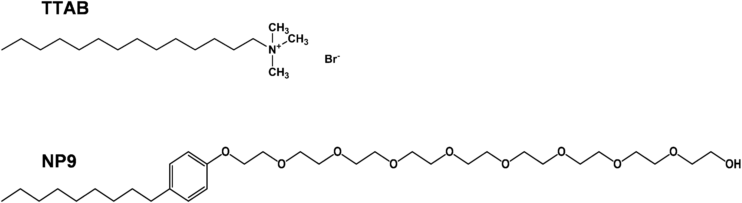 | ||
| Fig. 1 Structures of NP9 and TTAB. | ||
The aggregation of the particles was studied using transmission electron microscopy (TEM) and dynamic light scattering (DLS). The performance of the catalysts was studied with voltammetry using a rotating ring disc electrode.
2. Experimental
Milli-Q ultra pure water, with resistivity ≥18 MΩ cm, was used throughout. All glassware used for nanoparticle synthesis was thoroughly cleaned by soaking in aqua regia followed by rinsing with copious amounts of Milli-Q water.2.1 Synthesis of Pt + TTAB nanoparticles
The method of Lee et al.12 was used to prepare the Pt + TTAB nanoparticles. Briefly, 30 mL of a 0.23 M aqueous solution of TTAB (Aldrich 99%) was mixed with 10 mL of a 6.4 mM aqueous solution of K2PtCl6 (Sigma Aldrich 99.9%) at room temperature (20 °C). (The critical micelle concentration (cmc) of TTAB is 1.0 × 10⁻³ mol dm−3.30) The mixture was heated at 50 °C for about 5 minutes until the solution became clear. The vial was capped with a rubber septum immediately after adding 10 mL of an ice-cold, aqueous 0.15 M solution of NaBH4 (Sigma Aldrich). The H2 gas pressure inside the vial was released through a needle in the septum for 10 minutes. The needle was then removed and the solution was stirred at 50 °C for a further 6 hours.A repeated centrifugation/re-dispersion procedure was used to remove excess surfactant and soluble inorganic species. The dispersions were centrifuged for 20 minutes at 20![[thin space (1/6-em)]](https://www.rsc.org/images/entities/char_2009.gif) 000 rpm and 4 °C in a Sigma 3K30 refrigerated centrifuge. The supernatant was discarded, and the precipitate re-dispersed in Milli-Q water. The process was repeated once.
000 rpm and 4 °C in a Sigma 3K30 refrigerated centrifuge. The supernatant was discarded, and the precipitate re-dispersed in Milli-Q water. The process was repeated once.
2.2 Synthesis of Pt + NP9 nanoparticles
A similar procedure was adapted to prepare stable Pt + NP9 nanoparticles. In this case 73 mL of an aqueous solution of 7.8 mM NP9 (Aldrich 99%) was heated at 50 °C and 10 mL of a 1.36 mM solution of K2PtCl6 (Sigma Aldrich 99.9%) was added. (The cmc of NP9 is 7.4 × 10−5.30) The mixture was stirred at 50 °C for 4 hours.The Pt + NP9 particles are smaller than the Pt + TTAB particles. They were centrifuged as described above but at 26000 rpm for 1.5 hours and the process was repeated once.
2.3 Nanoparticle characterization
The Pt and surfactant content of the purified colloidal Pt was determined as follows. Known volumes of catalyst ink were added to aluminium oxide crucibles and dried in a vacuum oven overnight at 60 °C, prior to thermogravimetric analysis (TGA) to determine Pt and surfactant contents.The nanoparticles were imaged using transmission electron microscopy (JEOL 1200ex TEM for Pt + TTAB and Tecnai F20 HRTEM for Pt + NP9) and the hydrodynamic size was determined with dynamic light scattering (DLS) using a Beckman Coulter DelsaNano.
2.4 Catalyst ink preparation (Pt/C)
Pt nanoparticles were deposited on a carbon support in a Pt/C catalyst ink prior to electrochemical characterization. Vulcan XC-72R carbon black (Fuel Cell Store) was dispersed in Milli-Q water at a concentration of 0.4 mg mL−1. Nafion® was added to give a weight ratio of Nafion®:carbon black of 1:2.4 in the dry catalyst layer. The mixture was sonicated in an ultrasonic bath for 30 minutes to produce a uniform, stable dispersion free from coarse agglomerates. A measured amount of purified colloidal Pt was added to the Vulcan XC-72R dispersion to give a ratio of 45.9% Pt/C and the mixture was sonicated for a further 30 minutes. The surfactant-stabilized Pt/C was compared against a catalyst ink prepared using an equivalent method using TKK (TEC10E50E) 45.9 wt% Pt/C commercial catalyst.
2.5 Electrochemical measurements
Electrochemical measurements were carried out using a Metrohm Autolab PG302N potentiostat with an FRA2 impedance module, a SCAN250 analogue scan generator and a BA bipotentiostat/array. The jacketed glass electrochemical cell was enclosed in a grounded Faraday cage. A reversible hydrogen electrode (RHE) was used as reference electrode, to avoid contamination with impurities. This was prepared in-house and was similar to that described by Garsany.31 Counter electrodes for this study were made from Pt gauze (300 mesh, Alfa Aesar) with surface areas of >10 cm2, which were flame-annealed prior to experiments.Rotating ring disc electrodes (RRDE) with removable 5 mm diameter glassy carbon and Pt discs enclosed in PTFE with Pt ring were purchased from Pine Instruments (USA). The diameters of the Pt and carbon discs were found, by white light interferometry, to be 5 mm within 0.01 mm. The electrodes were polished for 5 minutes on Microcloth™ (Buehler) using aqueous alumina slurries of 1 μm, 0.3 μm and 0.05 μm grain size in sequence. The polished electrodes were rinsed well with Milli-Q water, then sonicated (40 kHz bath) for 3 minutes in Milli-Q water to remove any residual alumina. For electrochemical characterization, working electrodes were prepared by pipetting an 11.5 μL aliquot of Pt/C catalyst dispersion onto a 5 mm glassy carbon disc electrode to achieve a Pt loading of 20 μg cm−2 and dried at room temperature overnight. The quality of the catalyst films produced was checked under an optical microscope. In each case, the catalyst appeared evenly dispersed over the electrode surface.
It is important to use the correct Pt loading in RDE experiments.32 If the catalyst loading is too high, and catalyst films are thicker than 0.1 μm, the mass-transport characteristics of the RDE are no longer satisfied.33,34 Factors such as agglomerate structure, particle contact and diffusion properties of oxygen in the ionomer film start to influence specific activity. Also, the net activity becomes so high that the kinetic region becomes very small, and the polarization curve very steep, leading to problems with precision of the potential reading. If the catalyst loading is too low, the supported catalyst is no longer capable of spreading completely over the surface of the glassy carbon support. The optimum loading depends on the dispersion of each catalyst and may differ considerably. Therefore, it was determined for each catalyst individually, using the method described by Mayrhofer et al.32 The loading of 20 μg cm−2 (Pt) was taken as the optimum loading, for which the catalyst is spread completely over the surface of the glassy carbon support and the film is not too thick.
The electrolyte solution was 0.1 M HClO4 (prepared from 70% TraceSelect, Sigma) and was de-oxygenated by purging with ultra-pure N4.8 nitrogen (BOC Special Gases). The electrolyte was saturated with oxygen by bubbling N5 oxygen (BOC Special Gases). Fresh electrolyte was prepared for each working electrode. Great care was taken to avoid contamination: all glassware was thoroughly cleaned prior to use by heating in 1:1 concentrated HNO3:H2SO4, followed by thorough rinsing with Milli-Q water. While measurements were being taken, the appropriate gas was allowed to flow above the solution, maintaining positive pressure. The cell temperature was maintained at 25 °C using a thermostated circulating water bath.
The working electrode was mounted in an RRDE assembly and immersed in the electrolyte, taking care to remove any air bubbles from the electrode surface by rotating the electrode briefly at 1000 rpm. The working electrode was cycled between +0.05 and +1.0 V at 250 mV s−1 for up to 200 cycles, until stable cyclic voltammograms were observed.35 The cyclic voltammograms were recorded using analogue scan cyclic voltammetry at 25 mV s−1 between +0.05 and +1.1 V.
The oxygen reduction reaction (ORR) polarization curves were measured and corrected for capacitive current and ohmic resistance of the solution. Background linear sweep voltammograms (LSVs) were recorded whilst still under N2, from +0.05 to +1.1 V at 25 mV s−1 at the following rotation rates 400, 800, 1200, 1600, 2000, 2400 and 2800 rpm. This background current was subtracted from the experimental ORR current to eliminate any contributions of capacitive current. The Ohmic resistance of the electrolyte was determined using electrochemical ac impedance measurements at 10 kHz, with an ac perturbation of 5 mV. The electrolyte was then bubbled with oxygen (N5 ultra-high purity, BOC Special Gases) for at least 30 minutes. LSV scans were then repeated in the O2-saturated electrolyte at the same rotation rates, with oxygen flowing over the surface of the electrolyte. The Pt ring was maintained at +1.1 V. The oxygen concentration was measured using a Clark cell at intervals throughout the ORR experiment and was found to remain constant at (1.02 ± 0.15) × 10−6 mol cm−3. This is close to but slightly lower than the commonly used value of 1.26 × 10⁻⁶ mol cm−3 (at 25 °C).36,37
3. Results and discussion
3.1 Physical characterization
Pt nanoparticles were prepared as described in the experimental section and characterized by TGA to determine the amount of Pt and surfactant. Fig. 2 shows the relevant thermogravimetric mass loss profiles for the Pt nanoparticle dispersions and the derived Pt and surfactant content is shown in Table 1. Both samples contain a large excess of surfactant. No further attempt was made to remove this surfactant.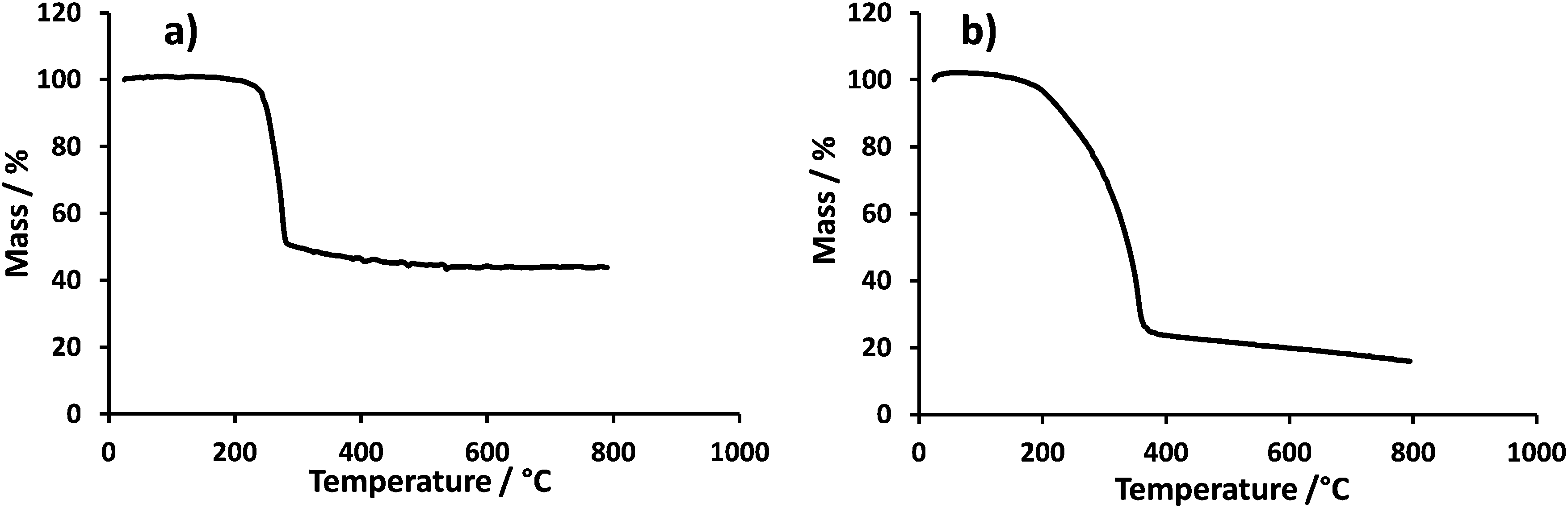 | ||
| Fig. 2 Thermogravimetric mass loss profiles obtained in air with a 50 K min−1 thermal ramp: (a) Pt + TTAB, (b) Pt + NP9. | ||
| Concentration Pt/mg mL−1 | Concentration surfactant/mg mL−1 | |
|---|---|---|
| Pt + TTAB | 3.85 | 4.93 |
| Pt + NP9 | 2.54 | 8.64 |
Fig. 3 and 4 show representative TEM images of the as-synthesized Pt nanoparticles prepared with TTAB and with NP9. The size distributions measured by two different methods are shown. The TEM images show particles dried onto a formvar-coated carbon-on-copper TEM specimen grid. The size of individual particles was measured from the images, using ImageJ software,38 and the results plotted in the histograms (b). The mean size of the Pt + TTAB particles is 12 nm with a standard deviation of 2.3 nm and the mean size of the Pt + NP9 particles is 2.8 nm with a standard deviation of 0.7 nm.
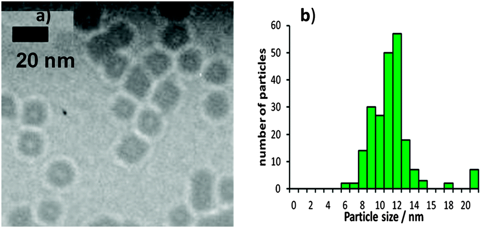 | ||
| Fig. 3 (a) TEM images of as-synthesized Pt nanoparticles prepared with TTAB (Pt + TTAB) along with (b) particle size distributions. | ||
 | ||
| Fig. 4 (a) TEM images of as-synthesized Pt nanoparticles prepared with NP9 (Pt + NP9) along with (b) their particle size distributions. | ||
Both the Pt + TTAB and Pt + NP9 appear to be stable dispersions, showing no particle sedimentation after standing for several weeks. The DLS technique was used to give an estimate of average particle size in aqueous dispersion and the results are shown in Fig. 5. DLS is a light-scattering technique39–42 in which the intensity of laser light scattered by particles undergoing Brownian motion is used to determine their size distribution. The hydrodynamic diameter is expected to be greater than the actual diameter of the Pt particle (measured using TEM), as the hydrodynamic diameter includes adsorbed surfactant layers. In the case of Pt + NP9, the adsorbed NP9 could cause the hydrodynamic diameter to be double that of the Pt particle. In the case of Pt + TTAB, the TTAB is likely to adsorb as a bilayer as described previously,43 which could add 4 nm to the diameter. In both cases, size distributions obtained using DLS are much broader and the average particle size is approximately 10× those obtained from TEM. The results suggest that the particles are forming some aggregates when dispersed in water and the DLS technique measures aggregate size. However, a major limitation of DLS is that it is inherently sensitive to the presence of larger particles in a sample. This is because, using the Rayleigh approximation, the intensity of scattered light is proportional to the sixth power of the particle radius. The scattered intensity of any larger particles or aggregates contributes heavily to the DLS measurement, whereas the scattered intensity from the smaller particles is lost in the background signal. Thus even a few large particles or aggregates in a sample will dominate the signal, resulting in an over-estimate in the mean diameter.44
 | ||
| Fig. 5 Particle size distributions measured by DLS (a) Pt +TTAB, (b) Pt + NP9. | ||
Fig. 6 shows representative TEM images of the catalysts loaded on carbon black (Vulcan XC-72). The nanoparticles synthesized with TTAB and NP9 are compared with the commercial catalyst TKK. The Pt + NP9/C catalyst has Pt particles of similar size to the TKK catalyst (2.8 nm). Both images show Pt nanoparticles evenly dispersed over the carbon support. The Pt + TTAB particles are larger, >10 nm, and are not as evenly dispersed over the carbon support.45
 | ||
| Fig. 6 TEM images of carbon supported Pt nanoparticles (a) (Pt + TTAB/C), (b) (Pt + NP9/C), (c) TKK (TEC10E50E). | ||
3.2 Electrochemical characterization
Fig. 7a shows the cyclic voltammograms (CVs) of two different platinum nanoparticle films (Pt + NP9/C and TKK) compared with that of the 5 mm Pt disc electrode. The TKK catalyst voltammogram has the characteristic H desorption peaks46 at 0.14 and 0.21 V, along with the corresponding cathodic adsorption peaks. These peaks compare well with those at 0.12 and 0.22 V for the Pt disc. The peak at 0.12 V is thought to result from hydrogen underpotential deposition (Hupd) on Pt(110) sites, while the peak at 0.22 V corresponds to Pt(100)-type step sites or terrace sites close to steps and high co-ordination edge and corner Pt sites.47–52 In the Pt + NP9/C electrochemistry they are mostly lost. It is possible that the surfactant molecules may be preferentially adsorbing onto the Pt crystal sites usually responsible for the more distinct Hupd features.46,53 The other important difference in the voltammetry between the TKK catalyst and Pt + NP9/C films is the greatly reduced magnitude of the peaks for adsorption and desorption of oxygen species on Pt. For the TKK catalyst this peak occurs at ca. 60 mV negative of that observed for the polycrystalline Pt disc. These results are in agreement with those of Gasteiger et al.,54 who attribute the negative shift to increased binding strength of OHads species on the TKK catalyst than on Pt(poly). They comment further that these species have an adverse effect on the O2-reduction reaction. The corresponding peak for the Pt + NP9/C catalyst is very small but occurs at a similar negative potential to that of the polycrystalline Pt disc, indicating substantially reduced binding of OHads species on the Pt + NP9/C catalyst. The CV for the Pt + TTAB/C nanoparticles is featureless. Apparently, the surface of the particles is blocked over the whole potential range. At positive potentials, the oxide formation may be suppressed by bromide adsorption, whereas at negative potentials, TTA+ ions will be electrostatically attracted to the surface, blocking adsorption of other species. | ||
| Fig. 7 Cyclic voltammograms of Pt/C catalysts 20 μg Pt per cm2 on 0.196 cm2 GC electrodes in N2-saturated 0.1 M HClO4 at 25 °C. Scan rate 25 mV s−1. Each compared with 0.196 cm2 Pt disc electrode (a) current (I/A) vs. potential, (b) Pt-surface area normalised current densities (j/mA cm−2vs. potential), (c) CO stripping voltammogram. | ||
Electrochemical surface areas (ECSAs) for the films were measured by integrating the desorption waves for underpotentially deposited hydrogen and assuming a charge passed per unit area of Pt of 210 μC cm−2.54 These values are given in Table 2, along with an estimate of the theoretical area obtained from the loading used, assuming spherical particles of the mean diameter measured from TEM results. The ECSA measured for the TKK catalyst compares well with previously reported values of ca. 90 m2 g−1.35 The Pt + NP9/C particles have an electrochemical surface area that is <25% of that for the TKK catalyst, despite equal platinum loadings and particle sizes (2.8 nm), suggesting that the NP9 blocks 75% of the surface Pt atoms to H adsorption. The shape of the CV in the Hupd region suggests that the NP9 surfactant is adsorbing first on edge and corner sites. Calculations55 suggest that 2.5 nm nanoparticles consist of approximately 75% edge and corner sites and 20% Pt(111). In Fig. 7b the CVs are normalized for electrochemical surface area, which highlights the suppression of Pt oxide formation and reduction on Pt + NP9/C.
| ECSA/m2 g−1 | Mean diameter/nm | Surface area/m2 g−1 (calculated) | |
|---|---|---|---|
| TKK | 91 | 2.8 | 98 |
| Pt + NP9/C | 22 | 2.8 | 98 |
| Pt + TTAB/C | 1.7 | 12 | 23 |
The CO-stripping curves shown in Fig. 7c were recorded in CO-free solution after adsorbing CO at 0.05 V for 30 minutes in CO-saturated solution. The total voltammetric charge was calculated from the background-corrected area under the CO stripping peak.32,56,57 The charge calculated for Pt + NP9/C is <20% that for the TKK catalyst. This is in agreement with the Hupd results, suggesting that the NP9 surfactant is blocking 80% of the Pt sites. The CO oxidation peak for Pt + NP9/C occurs at 0.95 V, compared with 0.85 V for the TKK catalyst. This is likely to result from the low coverage of OHads, on Pt + NP9/C, which is required for CO oxidation.58
 | ||
| Fig. 8 I R-corrected, background-subtracted RRDE data at various rotation rates: for Pt/C catalysts 20 μg Pt per cm2 geometric on 0.196 cm2 GC electrodes in O2-saturated 0.1 M HClO4 at 25 °C. (a) Ring current (ring potential held at 1.1 V), (b) disc current. | ||
The oxygen reduction reaction is a multistep process in which more than one reaction pathway can be followed. The mechanism of the reaction is depicted in Scheme 1.45
 | ||
| Scheme 1 Pathways for the oxygen reduction reaction, based on ref. 44. | ||
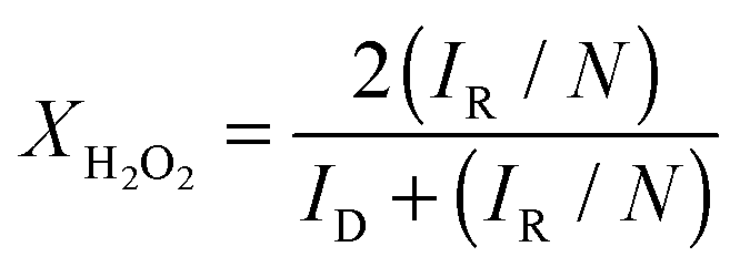
The reaction can proceed via a direct, 4-electron pathway that leads to water as a product. Alternatively, the reaction can proceed via a 2-electron pathway to hydrogen peroxide, which can either diffuse away from the surface or be further reduced to water in a 2-electron process. During the RRDE experiment, the ring is held at a positive potential, at which hydrogen peroxide is oxidized. In this way, hydrogen peroxide intermediates produced during the ORR at the disc can be detected by monitoring the current of the ring electrode. The Pt ring potential in these experiments was held at +1.1 V, such that the reaction occurring at the ring was entirely diffusion-limited, and the ring current was used to investigate the selectivity of the reaction. Visual inspection of the RRDE data in Fig. 8 indicate that the ORR at the Pt + TTAB/C catalyst produces the most hydrogen peroxide and that at the Pt disc the least. The number of electrons transferred, n, can be quantified from the disc and ring currents using eqn (1):60
 | (1) |
 | (2) |
 | ||
| Fig. 9 (a) n as a function of potential, calculated from the RRDE data acquired at 1600 rpm for each catalyst, using eqn (1). (b) Fraction of H2O2 formation during O2 reduction on Pt + NP9/C, TKK and Pt disc and Pt + TTAB/C at 25 °C in 0.1 M HClO4 saturated with O2. Calculated from the data in Fig. 8 (at 1600 rpm) using eqn (2) with N = 0.21. | ||
Values of XH2O2 are plotted as a function of potential in Fig. 9b. The value obtained for the TKK and NP9 catalysts at E = +0.1 V is 0.1, in good agreement with previous work on Pt/C catalysts with similar particle sizes.63 For each electrode, a significant increase in XH2O2 is observed in the Hupd region (E < 0.2 V). This observation has previously been attributed to competitive adsorption of hydrogen, which results in blocking of active sites, hindering the dissociative adsorption of oxygen molecules.21
Previous studies have shown that the fraction of H2O2 production in the Hupd region is higher for Pt particles supported on carbon64 and for Pt surfaces in contact with a layer of adsorbed Nafion®.63,65Fig. 9 shows that, although the amount of peroxide production is negligible over the range of typical operating potentials of the PEMFC cathode (+0.6 V to +1.0 V), at potentials negative of +0.3 V, the extent of peroxide formation is significantly higher on the Pt + NP9/C and TKK catalysts than on the Pt disc. The decrease in tendency towards the 4-electron pathway may arise from a combination of particle size effects and modifications to the Pt surface by adsorbed Nafion®. The large excess of NP9 surfactant, present in the Pt + NP9/C catalyst, did not significantly affect the proportion of H2O2 produced. The reason for this could be that the NP9 surfactant adsorbs preferentially on edge and corner sites of the nanoparticles, which tend to be blocked by OHads in the potential range of interest. Terrace sites may be left free of directly adsorbed surfactant, allowing O2 adsorption and reduction to occur without affecting the mechanism.
The amount of hydrogen peroxide produced is significantly higher on the Pt + TTAB/C catalysts, which is likely to result from blocking of sites by bromide counterions from the TTAB surfactant. Bromide ions adsorbed on Pt are known to increase H2O2 oxidation currents on the ring electrode, implying that in the presence of bromide ions the ORR does not proceed entirely through the 4-electron pathway.66 This has been attributed to site blocking, such that pairs of adjacent Pt sites, required for the splitting of the O–O bond, are less abundant (similarly to the case of competitive adsorption of hydrogen).
 | (3) |
| jL = 0.2006nFCD2/3v−1/6ω1/2 | (4) |
21,37), v is the kinematic viscosity of the solution (1.009 × 10⁻² cm2 s−121) and ω is the rotation rate of the electrode (in rpm). Koutecky–Levich plots (1/j vs. ω−1/2) are presented in Fig. 10. The plots are linear, as predicted by eqn (3) and (4).
 | ||
| Fig. 10 Koutecky–Levich plots calculated from data in Fig. 8b. (left) Pt + TTAB/C, (centre) Pt + NP9/C TKK, (centre) TKK, (right) Pt disc. | ||
The kinetic currents for the mixed kinetic-diffusion control of the ORR were determined from the Koutecky–Levich plots and used to construct Tafel plots, presented in Fig. 11a. Kinetic currents were also extracted from the ORR disc currents at 1600 rpm, using a rearrangement of the Koutecky–Levich eqn (5), and used to construct mass transfer-corrected Tafel plots, shown in Fig. 11b. The data for Pt + TTAB/C are not plotted because of the large error in calculation of the ECSA.
 | (5) |
 | ||
| Fig. 11 Mass transport corrected current densities for the ORR on a Pt + NP9/C thin-film RRDE and TKK (20 μg Pt cm2), obtained from positive sweeps (25 mV s−1, 1600 rpm) in 0.1 M HClO4 saturated with O2 at 25 °C. (a) surface area specific current densities (calculated from KL plot), (b) surface area specific current densities (calculated from results at 1600 rpm), and (c) mass-specific current densities. | ||
The plots in Fig. 11a and b are normalized with respect to ECSA and show good agreement with one another. From the curvature of the Tafel plots it is clear that there is no single Tafel slope for the reaction in the potential range 0.9–0.78 V. The slope is around −60 mV dec−1 at E > 0.85 V but doubles to −120 mV dec−1 for E < 0.8 V. This finding is in good agreement with previous work.68,69 The change in slope has been attributed either to a change from Temkin to Langmuir adsorption of reaction intermediates or to an increase in coverage by surface oxides.46
The results show that in the kinetically controlled potential region the area-specific activity is highest for the Pt disc. This is in agreement with the work of Mayrhofer et al.,70 who found that for the ORR the increase in oxophilicity of smaller particles leads to a decrease in specific activity because OH can effectively block the active sites required for the adsorption of O2 and the splitting of the O–O bond. The specific activity of the TKK catalyst at 0.9 V (3.1 A m−2) compares well with values previously reported for this catalyst (2.92 A m−2 in the same electrolyte at 25 °C and a sweep rate of 10 mV s−1 reported by Takahashi and Kocha;35 2.9 A m−2 in the same electrolyte at 60 °C [N.B. the solubility of oxygen is lower at this temperature] and a sweep rate of 20 mV s−1 reported by Gasteiger et al.54). The area–specific activity for Pt + NP9/C is higher than that for the TKK catalyst, which suggests less blocking of active sites with OH species. It appears, from the CV (Fig. 7a), that the NP9 surfactant inhibits strongly OH adsorption on the Pt surface, which, interestingly, may explain the higher specific activity observed. The results in Fig. 8 and 11 show that the ORR is not completely blocked by the NP9 surfactant molecules.
To allow for comparison with the Pt + TTAB/C catalyst, the kinetic currents obtained using eqn (5) were also normalized per mass Pt and these data are presented in Fig. 11c. This quantity is also highly relevant from the point of view of the cost of catalyst required for a fuel cell. The mass activity of the TKK catalyst at 0.9 V (277 A g−1) compares well with literature values (266 A g−1 at 25 °C reported by Takahashi and Kocha35 and 220 A g−1 at 60 °C [N.B. the oxygen solubility is lower at this temperature] reported by Gasteiger et al.54). The mass activity–potential plot in Fig. 11c shows that the Pt + NP9/C catalyst has similar mass activity to the TKK catalyst, despite the presence of excess NP9 surfactant. The Pt + TTAB/C catalyst shows considerably worse mass activity. This effect could be caused by several factors. The larger size of the Pt + TTAB/C particles means that they have a smaller surface area per unit mass than the Pt + NP9/C and TKK catalysts. Also, the activity will be reduced by the site-blocking effect of the bromide counter-ions of the cationic surfactant; bromide has been shown previously to have a detrimental effect on ORR activity.59,66 The Pt + TTAB/C particles are mostly cubic and will mainly have Pt(100) crystal faces, which are known to be less active toward the ORR in perchloric acid solution than Pt(110) and Pt(111) faces.71–73 It is also possible that the presence of the surfactant inhibits electron transfer between the catalyst and the carbon support, although this effect was not seen for the NP9-stabilized catalysts. It is not possible to separate the effect of bromide ions from that of the organic cation without substantial additional work, so we defer this investigation to a future paper. The similarity of the RDE curves with those published for bromide-containing solutions are strong evidence that bromide is at least partially responsible for the lower activity of the Pt + TTAB/C catalyst.
A kinetic analysis of the ring and disc currents was employed to provide more detail on the differences in selectivity between the catalysts studied. Using Scheme 1, a comparison of the rate constants k1 (representing 4-electron reduction to water) and k2 (representing 2-electron reduction to hydrogen peroxide) can be carried out, if it is assumed that the chemical decomposition and electrochemical oxidation of hydrogen peroxide are minimal and the adsorption and desorption of hydrogen peroxide are rapid and in equilibrium. Diagnostic plots of ID/IRvs. ω−1/2 are presented for each catalyst in Fig. 12. The intercepts of these plots are not equal, which indicates that a parallel reaction pathway operates (in agreement with the conclusions drawn from Fig. 9). Hsueh and Chin74 developed the model further to determine the rate constants from the plots in Fig. 12 and plots of IDL/(IDL − ID) vs. ω−1/2:
 | (6) |
 | (7) |
 | (8) |
 | (9) |
 | (10) |
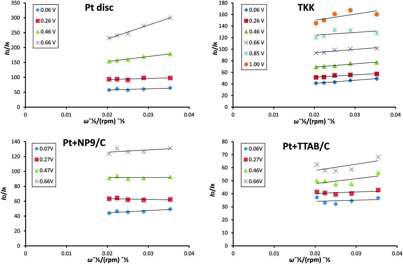 | ||
| Fig. 12 Plots of ID/IRvs. ω−1/2 calculated from data presented in Fig. 8. | ||
The rate constants are usually normalized for ECSA for comparison of the catalysts investigated. Since the ECSA for the Pt + TTAB/C catalyst is so small and thus the error associated with its calculation so large, we decided to compare instead the ratio of the rate constants k1 and k2. Fig. 14 presents plots of k1/k2 as a function of potential for each catalyst studied. The plots for nanoparticulate catalysts indicate a steady fall in the ratio as the potential is made more negative, which reflects the tendency for the fraction of hydrogen peroxide to increase at more negative potentials. Significantly, the ratio is smallest for the Pt + TTAB/C catalyst, which shows that the rate of production of hydrogen peroxide is highest for this catalyst. This is likely to be a result of a number of factors, particularly blocking of active sites by bromide ions, which reduces the availability of adjacent sites for oxygen to adsorb and so reduces the extent of dissociative adsorption, essential for the full reduction to water. The lower ratio may also be a reflection of different facets exposed: since the Pt + TTAB/C particles are cubic, it is likely that facets are predominantly (100) and (100) single crystals exhibit lower activity and more H2O2 production than (111) or (110) faces of Pt.50 This result shows that the lower mass activity (jk) observed for Pt + TTAB/C catalysts in Fig. 11c does not result from lower surface area alone but also from the intrinsic nature of the catalyst. Interestingly, the k1/k2 ratio is higher for Pt + NP9/C catalysts than for the TKK catalyst, which may be a result of the inhibition of OH adsorption observed in Fig. 7a and discussed above.
 | ||
| Fig. 13 Plots of IDL/(IDL − ID) vs. ω−1/2 calculated from data presented in Fig. 8. | ||
 | ||
| Fig. 14 Plots of k1/k2 as a function of potential. | ||
4. Conclusion
With careful choice of surfactant it may not be necessary to remove all the surfactant used in the preparation of nanoparticles and the surfactants may have a beneficial effect. Here, well-dispersed Pt nanoparticles were prepared using the non-ionic surfactant NP9. These particles show good catalytic activity towards the ORR without extensive removal of surfactant. The results presented show that adsorbed surfactant NP9 on Pt nanoparticle surfaces reduces the measured ECSA but does not adversely affect the ORR performance. The reason for this is thought to be that the NP9 surfactant adsorbs preferentially on edge and corner sites of the nanoparticles, which tend to be blocked by OHads in the potential range of interest. The choice of surfactant used in the preparation of catalyst nanoparticles obviously affects the nanoparticle size and shape, which in turn affects their catalytic activity. It is difficult to separate the factors involved. The Pt nanoparticles prepared with the cationic surfactant TTAB displayed RRDE voltammetry similar to that observed for Pt in bromide-containing solutions and a greater tendency towards a 2e− reduction of oxygen, suggesting that bromide ions are blocking active sites. Kinetic analysis showed that reduced mass activity was partly a result of this site-blocking and possibly shape effects, not simply a lower surface area resulting from larger particle size. In summary, by careful choice of surfactant used in the synthesis of Pt nanoparticles, it is possible to generate catalysts that perform well in terms of activity and selectivity towards the 4e− pathway, without the need for extensive surfactant removal processes.Acknowledgements
The authors acknowledge financial support from the Engineering and Physical Sciences Research Council through the Doctoral Training Centre: Centre for Fuel Cell and Hydrogen Research (Grant Number EP/G037116/1).References
- Z. Liu, M. Shamsuzzoha, E. T. Ada, W. M. Reichert and D. E. Nikles, J. Power Sources, 2007, 164, 472–480 CrossRef CAS PubMed.
- M. Arenz, K. J. J. Mayrhofer, V. Stamenkovic, B. B. Blizanac, T. Tomoyuki, P. N. Ross and N. M. Markovic, J. Am. Chem. Soc., 2005, 127, 6819–6829 CrossRef CAS PubMed.
- V. R. Stamenkovic, B. Fowler, B. S. Mun, G. Wang, P. N. Ross, C. A. Lucas and N. M. Marković, Science, 2007, 315, 493–497 CrossRef CAS PubMed.
- Z. Peng and H. Yang, Nano Today, 2009, 4, 143–164 CrossRef CAS PubMed.
- J. W. Guo, T. S. Zhao, J. Prabhuram and C. W. Wong, Electrochim. Acta, 2005, 50, 1973–1983 CrossRef CAS PubMed.
- D.-H. Lim, W.-D. Lee, D.-H. Choi, D.-R. Park and H.-I. Lee, J. Power Sources, 2008, 185, 159–165 CrossRef CAS PubMed.
- K. Okaya, H. Yano, H. Uchida and M. Watanabe, ACS Appl. Mater. Interfaces, 2010, 2, 888–895 CAS.
- S. Singh and J. Datta, J. Mater. Sci., 2010, 45, 3030–3040 CrossRef CAS PubMed.
- H. Bönnemann, W. Brijoux, R. Brinkmann, R. Fretzen, T. Joussen, R. Köppler, B. Korall, P. Neiteler and J. Richter, J. Mol. Catal., 1994, 86, 129–177 CrossRef.
- X. Wang and I. M. Hsing, Electrochim. Acta, 2002, 47, 2981–2987 CrossRef CAS.
- Y. Borodko, S. M. Humphrey, T. D. Tilley, H. Frei and G. A. Somorjai, J. Phys. Chem. C, 2007, 111, 6288–6295 CAS.
- H. Lee, S. Habas, S. Kweskin, D. Butcher, G. Somorjai and P. Yang, Angew. Chem., Int. Ed., 2006, 45, 7824–7828 CrossRef CAS PubMed.
- J. Prabhuram, X. Wang, C. L. Hui and I. M. Hsing, J. Phys. Chem. B, 2003, 107, 11057–11064 CrossRef CAS.
- R. J. Hunter, Introduction to modern colloid science, Oxford University Press, Oxford, 1993 Search PubMed.
- T. Tadros, Kirk-Othmer encyclopedia of chemical technology, 2006 Search PubMed.
- K. Mathai and R. Ottewill, Trans. Faraday Soc., 1966, 62, 750–758 RSC.
- K. Mathai and R. Ottewill, Trans. Faraday Soc., 1966, 62, 759–769 RSC.
- A. Vrij, Pure Appl. Chem., 1976, 48, 471 CrossRef CAS.
- F. El Kadiri, R. Faure and R. Durand, J. Electroanal. Chem. Interfacial Electrochem., 1991, 301, 177–188 CrossRef CAS.
- V. Stamenkovic, N. M Markovic and P. Ross Jr, J. Electroanal. Chem., 2001, 500, 44–51 CrossRef CAS.
- N. M. Markovic, H. A. Gasteiger and P. N. Ross Jr, J. Phys. Chem., 1995, 99, 3411–3415 CrossRef CAS.
- D. Li, C. Wang, D. Tripkovic, S. Sun, N. M. Markovic and V. R. Stamenkovic, ACS Catal., 2012, 2, 1358–1362 CrossRef CAS.
- J. Monzó, M. Koper and P. Rodriguez, ChemPhysChem, 2012, 13, 709–715 CrossRef PubMed.
- B. Cornils and W. A. Herrmann, Applied homogeneous catalysis with organometallic compounds, VCH Weinheim etc., 1996 Search PubMed.
- B. Genorio, D. Strmcnik, R. Subbaraman, D. Tripkovic, G. Karapetrov, V. R. Stamenkovic, S. Pejovnik and N. M. Marković, Nat. Mater., 2010, 9, 998–1003 CrossRef CAS PubMed.
- Y.-H. Chung, D. Y. Chung, N. Jung and Y.-E. Sung, J. Phys. Chem. Lett., 2013, 4, 1304–1309 CrossRef CAS.
- Z. Q. Tian, S. P. Jiang, Z. Liu and L. Li, Electrochem. Commun., 2007, 9, 1613–1618 CrossRef CAS PubMed.
- C. Susut, D.-J. Chen, S.-G. Sun and Y. J. Tong, Phys. Chem. Chem. Phys., 2011, 13, 7467–7474 RSC.
- J. J. Pietron, Y. Garsany, O. Baturina, K. E. Swider-Lyons, R. M. Stroud, D. E. Ramaker and T. L. Schull, Electrochem. Solid-State Lett., 2008, 11, B161–B165 CrossRef CAS PubMed.
- M. J. Rosen and M. Dahanayake, Industrial utilization of surfactants: principles and practice, AOCS press Champaign, IL, 2000 Search PubMed.
- Y. Garsany, O. A. Baturina, K. E. Swider-Lyons and S. S. Kocha, Anal. Chem., 2010, 82, 6321–6328 CrossRef CAS PubMed.
- K. J. J. Mayrhofer, D. Strmcnik, B. B. Blizanac, V. Stamenkovic, M. Arenz and N. M. Markovic, Electrochim. Acta, 2008, 53, 3181–3188 CrossRef CAS PubMed.
- F. Gloaguen, P. Convert, S. Gamburzev, O. Velev and S. Srinivasan, Electrochim. Acta, 1998, 43, 3767–3772 CrossRef CAS.
- J. Perez, E. Gonzalez and E. Ticianelli, Electrochim. Acta, 1998, 44, 1329–1339 CrossRef CAS.
- I. Takahashi and S. S. Kocha, J. Power Sources, 2010, 195, 6312–6322 CrossRef CAS PubMed.
- J. S. Jirkovský, M. Halasa and D. J. Schiffrin, Phys. Chem. Chem. Phys., 2010, 12, 8042–8053 RSC.
- N. Wakabayashi, M. Takeichi, M. Itagaki, H. Uchida and M. Watanabe, J. Electroanal. Chem., 2005, 574, 339–346 CrossRef CAS PubMed.
- W. Rasband, Software, 2007 Search PubMed.
- R. Finsy, Adv. Colloid Interface Sci., 1994, 52, 79–143 CrossRef CAS.
- W. Winter, J. Polym. Sci., Polym. Lett. Ed., 1983, 21, 1020 CrossRef.
- R. Pecora, Dynamic light scattering: applications of photon correlation spectroscopy, Springer, 1985 Search PubMed.
- W. Anderson, D. Kozak, V. A. Coleman, Å. K. Jämting and M. Trau, J. Colloid Interface Sci., 2013, 405, 322–330 CrossRef CAS PubMed.
- J. E. Newton, J. A. Preece and B. G. Pollet, Int. J. Low-Carbon Technol., 2012, 7, 38–43 CrossRef CAS.
- C. M. Hoo, N. Starostin, P. West and M. L. Mecartney, J. Nanopart. Res., 2008, 10, 89–96 CrossRef CAS.
- A. Damjanovic, M. Genshaw and J. M. Bockris, J. Chem. Phys., 1966, 45, 4057 CrossRef CAS PubMed.
- N. Marković and P. Ross Jr, Surf. Sci. Rep., 2002, 45, 117–229 CrossRef.
- J. Solla-Gullón, P. Rodríguez, E. Herrero, A. Aldaz and J. M. Feliu, Phys. Chem. Chem. Phys., 2008, 10, 1359–1373 RSC.
- F. J. Vidal-Iglesias, R. M. Arán-Ais, J. Solla-Gullón, E. Herrero and J. M. Feliu, ACS Catal., 2012, 2, 901–910 CrossRef CAS.
- T. Schmidt, H. Gasteiger, G. Stäb, P. Urban, D. Kolb and R. Behm, J. Electrochem. Soc., 1998, 145, 2354–2358 CrossRef CAS PubMed.
- N. Markovic, H. Gasteiger and P. N. Ross, J. Electrochem. Soc., 1997, 144, 1591–1597 CrossRef CAS PubMed.
- J. Solla-Gullón, F. Vidal-Iglesias and J. Feliu, Annu. Rep. Prog. Chem., Sect. C: Phys. Chem., 2011, 107, 263–297 RSC.
- N. Alexeyeva, K. Tammeveski, A. Lopez-Cudero, J. Solla-Gullón and J. Feliu, Electrochim. Acta, 2010, 55, 794–803 CrossRef CAS PubMed.
- G. A. Attard, J. E. Gillies, C. A. Harris, D. J. Jenkins, P. Johnston, M. A. Price, D. J. Watson and P. B. Wells, Appl. Catal., A, 2001, 222, 393–405 CrossRef CAS.
- H. A. Gasteiger, S. S. Kocha, B. Sompalli and F. T. Wagner, Appl. Catal., B, 2005, 56, 9–35 CrossRef CAS PubMed.
- G. Tritsaris, J. Greeley, J. Rossmeisl and J. K. Nørskov, Catal. Lett., 2011, 141, 909–913 CrossRef CAS.
- S. Park, S. A. Wasileski and M. J. Weaver, J. Phys. Chem. B, 2001, 105, 9719–9725 CrossRef CAS.
- B. Grgur, N. Markovic and P. Ross, J. Phys. Chem. B, 1998, 102, 2494–2501 CrossRef CAS.
- A. López-Cudero, J. Solla-Gullón, E. Herrero, A. Aldaz and J. M. Feliu, J. Electroanal. Chem., 2010, 644, 117–126 CrossRef PubMed.
- N. M. Marković, C. A. Lucas, H. A. Gasteiger and P. N. Ross, Surf. Sci., 1996, 365, 229–240 CrossRef.
- E. Claude, T. Addou, J.-M. Latour and P. Aldebert, J. Appl. Electrochem., 1998, 28, 57–64 CrossRef CAS.
- W. Albery and S. Bruckenstein, Trans. Faraday Soc., 1966, 62, 1920–1931 RSC.
- U. Paulus, T. Schmidt, H. Gasteiger and R. Behm, J. Electroanal. Chem., 2001, 495, 134–145 CrossRef CAS.
- O. Antoine and R. Durand, J. Appl. Electrochem., 2000, 30, 839–844 CrossRef CAS.
- M. Inaba, H. Yamada, J. Tokunaga and A. Tasaka, Electrochem. Solid-State Lett., 2004, 7, A474–A476 CrossRef CAS PubMed.
- A. Ohma, K. Fushinobu and K. Okazaki, Electrochim. Acta, 2010, 55, 8829–8838 CrossRef CAS PubMed.
- N. M. Marković, H. A. Gasteiger, B. N. Grgur and P. N. Ross, J. Electroanal. Chem., 1999, 467, 157–163 CrossRef.
- A. J. Bard and L. R. Faulkner, Electrochemical Methods: Fundamentals and Applications, Wiley, New York, 2001 Search PubMed.
- M. Tarasevich, A. Sadkowski and E. Yeager, Compr. Treatise Electrochem., 1983, 7, 301–398 CAS.
- D. Sepa, M. Vojnovic and A. Damjanovic, Electrochim. Acta, 1981, 26, 781–793 CrossRef CAS.
- K. Mayrhofer, B. Blizanac, M. Arenz, V. Stamenkovic, P. Ross and N. Markovic, J. Phys. Chem. B, 2005, 109, 14433–14440 CrossRef CAS PubMed.
- J. Zhang, H. Yang, J. Fang and S. Zou, Nano Lett., 2010, 10, 638–644 CrossRef CAS PubMed.
- C.-H. Cui, H.-H. Li, X.-J. Liu, M.-R. Gao and S.-H. Yu, ACS Catal., 2012, 2, 916–924 CrossRef CAS.
- J. X. Wang, H. Inada, L. Wu, Y. Zhu, Y. Choi, P. Liu, W.-P. Zhou and R. R. Adzic, J. Am. Chem. Soc., 2009, 131, 17298–17302 CrossRef CAS PubMed.
- K. L. Hsueh, D. T. Chin and S. Srinivasan, J. Electroanal. Chem. Interfacial Electrochem., 1983, 153, 79–95 CrossRef CAS.
| This journal is © the Owner Societies 2014 |