 Open Access Article
 This Open Access Article is licensed under a
 Creative Commons Attribution 3.0 Unported Licence
Impedance analysis of secondary phases in a Co-implanted ZnO single crystal
M.
Younas
*ab,
L. L.
Zou
a,
M.
Nadeem
b,
Naeem-ur-Rehman
ac,
S. C.
Su
a,
Z. L.
Wang
a,
W.
Anwand
d,
A.
Wagner
d,
J. H.
Hao
e,
C. W.
Leung
e,
R.
Lortz
f and
F. C. C.
Ling
*a
aDepartment of Physics, The University of Hong Kong, Pokfulam Road, Hong Kong, P. R. China. E-mail: chuhan.pieas@gmail.com; ccling@hku.hk
bEMMG, Physics Division, PINSTECH, P.O. Nilore, Islamabad, Pakistan
cDepartment of Metallurgy and Materials Engineering, PIEAS, Nilore, Islamabad 45650, Pakistan
dInstitute of Radiation Physics, Helmholtz-Zentrum Dresden-Rossendorf, Bautzner Landstr. 400, 01328 Dresden, Germany
eDepartment of Applied Physics, The Hong Kong Polytechnic University, Hong Kong, P. R. China
fDepartment of Physics, Hong Kong University of Science and Technology, Clear Water Bay, Kowloon, Hong Kong, P. R. China
First published on 25th June 2014
Abstract
Co ions with 100 keV energy with a fluence of 1 × 1015 cm−2 are implanted into ZnO(0001) single crystals at 300 °C under vacuum. The resulting Co-implanted ZnO single crystals and the subsequent 750 °C and 900 °C annealed samples are analysed with respect to their structural, optical, electronic, magnetic and ac electrical properties. Photoluminescence and X-ray photoelectron spectroscopy results indicate the signatures of the Co2+ state and its substitution at the tetrahedrally coordinated Zn-sites. X-ray diffraction and X-ray photoelectron spectroscopy identify the presence of the ZnCo2O4 and Co3O4 phases in the 900 °C annealed sample. By comparing the resistance response of the identified phases towards different magnetic environments, the impedance spectroscopy results successfully identify two magnetic phases (ZnCo2O4 and Co3O4) and a paramagnetic (CoZn) phase for the 750 °C and 900 °C annealed samples, implying the extrinsic nature of room temperature ferromagnetism. The observed ferromagnetism in each sample is not of single origin, instead the mutual effects of the secondary phases embedded in the paramagnetic host matrix are in competition with each other.
1. Introduction
The forecast of carrier assisted high temperature ferromagnetism in transition metal doped diluted magnetic semiconductors (especially in p-type ZnO1) has encouraged the scientific community to search for a realistic diluted magnetic semiconductor for practical applications. The Co–ZnO material has been considered as a role model system for a wide range of diluted magnetic semiconductors after the ab initio theoretical prediction of intrinsic ferromagnetism2 and the sequential experimental observation of room temperature ferromagnetism (RT FM)3 in this class of material. Regardless of this great prospective, understanding whether RT FM is intrinsic4,5 or related to clustering or incipient development of secondary phases,6,7 or totally absent, is still controversial.8,9 Furthermore, RT FM also depends on sample preparation and growth conditions and many experimental studies have identified that RT FM is absent in near-perfect epitaxial Co-doped ZnO films.10,11In order to avoid problems associated with sample preparation, ion implantation is considered to increase sample preparation reproducibility and allows the precise control of the implanted ion concentration to overcome the solubility limit.12 Although a substantial amount of disorder will occur after ion implantation, ZnO exhibits a strong degree of dynamic annealing during ion bombardment (i.e. migration, interaction and recombination of ion-beam-generated intrinsic defects). Such an annealing process makes ZnO a radiation resilient material and it can bear high doses of irradiation without becoming amorphous. However, dynamic annealing is not 100% effective for full structural recovery of the lattice disorder. Dopant clusters and extended stacking faults may also accumulate during the ion bombardment process.13,14 Implantation at elevated temperatures may decrease the amount of disorder through the process of dynamic defect annealing and would also offer in situ thermal dopant activation.15
Our present study aims to investigate the different possible phases and their potential role in tuning the magnetic properties of high temperature (300 °C) Co-implanted n-type ZnO single crystals. X-ray diffraction (XRD) and X-ray photoelectron spectroscopy (XPS) can reveal the crystalline and electronic structures of secondary phases, respectively, but they fail to offer any magnetism related information. Magnetic probes, like vibrating sample magnetometers (VSM) and superconducting quantum interference devices (SQUID), can detect the overall magnetism but are unable to distinguish between the intrinsic FM and the contribution of the multiple phases in the material under observation. Therefore, more local probe studies are needed to fairly separate the multiple phases if they are playing a role. Impedance spectroscopy (IS) is an informative and exceptional characterizing tool in fundamental and applied materials research. It can be used to resolve the contribution of the different phases to the electrical properties, such as the contact effects, grains, grain boundaries, and any type of impurity inside a sample.16,17 Compared to other techniques, IS explicitly distinguishes among the strongly coupled processes having different proceeding rates,18–20 as well as the concealed multiple phases having diverse conductivities even if the concentrations of the phases are very low.21,22 However, conventional IS does not offer any direct magnetic information on the individual phases.
In this research work, high quality single crystals have been used as the raw material to avoid the grain boundary defects. These defects have much higher relaxation times compared to grains and normally act as a potential source to activate the RT ferromagnetism by confining transition metals or impurities.16,23 Structural and electronic information of the phases were studied by XRD, XPS and photoluminescence (PL), and the magnetic properties were investigated by VSM. IS was used to separate the potential phases and to study their magnetic properties with the measurements done without the magnetic field (NMF), with the magnetic field (MF) and then after retreating from the magnetic field (AMF). The magnetic properties of the identified phases were obtained by comparing their component resistances measured under the different magnetic environments. The origins of the observed phases were suggested according to the comprehensive information obtained from the XRD, XPS, PL and IS measurements.
2. Experimental
The raw material used was the undoped melted grown ZnO(0001) single crystal obtained from Cermet Inc., USA. Its carrier concentration and mobility are 5 × 1016 cm−3 and ∼203 cm2 V−1 s−1, respectively. Co ions with 100 keV energy and a fluence of 1015 cm−2 were implanted into the ZnO single crystal at 300 °C under vacuum. Secondary ion mass spectroscopic (SIMS) measurements carried out by Cameca (Model IMS 4F) yielded a Co depth profile extending to a depth of 200 nm and an intensity that peaked at 50 nm, which coincides well with Monte Carlo TRIM calculations.24 This corresponds to an average Co-doping concentration of 1019 cm−3 in the top 200 nm of depth. To further remove the ion-induced defects, post-implantation annealing is performed at 750 °C and 900 °C in Ar for 30 minutes. XRD was performed with a Bruker D8 Advance X-ray diffractometer using the Cu Kα line (0.1541 nm). PL measurements were performed with the 325 nm He–Cd laser line with samples mounted in a 10 K closed cycled He refrigerator. The grating monochromator employed has a focal length of 500 mm. The photons are detected by a photomultiplier tube (PMT) with the signal processed by a lock-in amplifier. The electronic structures of Co were studied by XPS using the MgKα line (Kratos Axis Ultra DLS system). The X-ray source and the C 1s line were taken as the standard. Magnetic measurements (M–H loop) were performed at room temperature using a Lakeshore Model 7300 series VSM. Room temperature IS measurements were performed within the frequency range of 1 Hz ≤ f ≤ 107 Hz using an Alpha-N analyzer (Novocontrol, Germany). To perturb the system, a low ac signal of 0.2 V was used. Fully automated WINDETA software was used for interfacing the experimental setup of the analyzer to the computer and for data acquisition. ZView (Complex Nonlinear Least Squares Immittance Data Fitting Program, Version 6.1-4/03/94) software was used for fitting and analyzing the measured impedance results within 1–2% fitting error. The IS measurements were carried out under null magnetic field (NMF), with a constant magnetic field of 0.3 T perpendicular to the sample surface (MF), and 10 minutes after retreating from the magnetic field (AMF).3. Results and discussions
3.1 Structural and electronic properties
The XRD patterns of Co-implanted ZnO samples (Fig. 1(a)) are dominated by the (002) peaks, which correspond to the c-axis orientated wurtzite ZnO structure. In comparison with pure ZnO single crystals, the intensity of the (002) peaks decreases for the Co-implanted samples, indicating the implantation-induced structural changes in the samples. The two new peaks are unambiguously observed in the slow scan XRD (30.5° to 32°) of the 900 °C annealed sample (ann900) as shown in Fig. 1(b). The typical (100) reflection of ZnO normally exists around 31.8° (∼32°)25,26 which is close to the newly observed peak positions in our ann900 sample. Therefore, in order to rule out the possibility of the (100) ZnO reflection due to the thermally induced reconstruction of ion-induced defects, the slow scan XRD for the 900 °C annealed Cu-implanted ZnO single crystal prepared under the same conditions is also shown in Fig. 1(b). The lattice mismatch of the Cu2+ ion (0.080 nm) and Zn2+ ion (0.083 nm) is very small, and may result in a small lattice distortion when implanted into ZnO.26 Within the detection limit of XRD, no peak around 31° related to the (100) ZnO reflection is observed for the Cu-implanted ZnO single crystals annealed at 900 °C (Fig. 1(b)).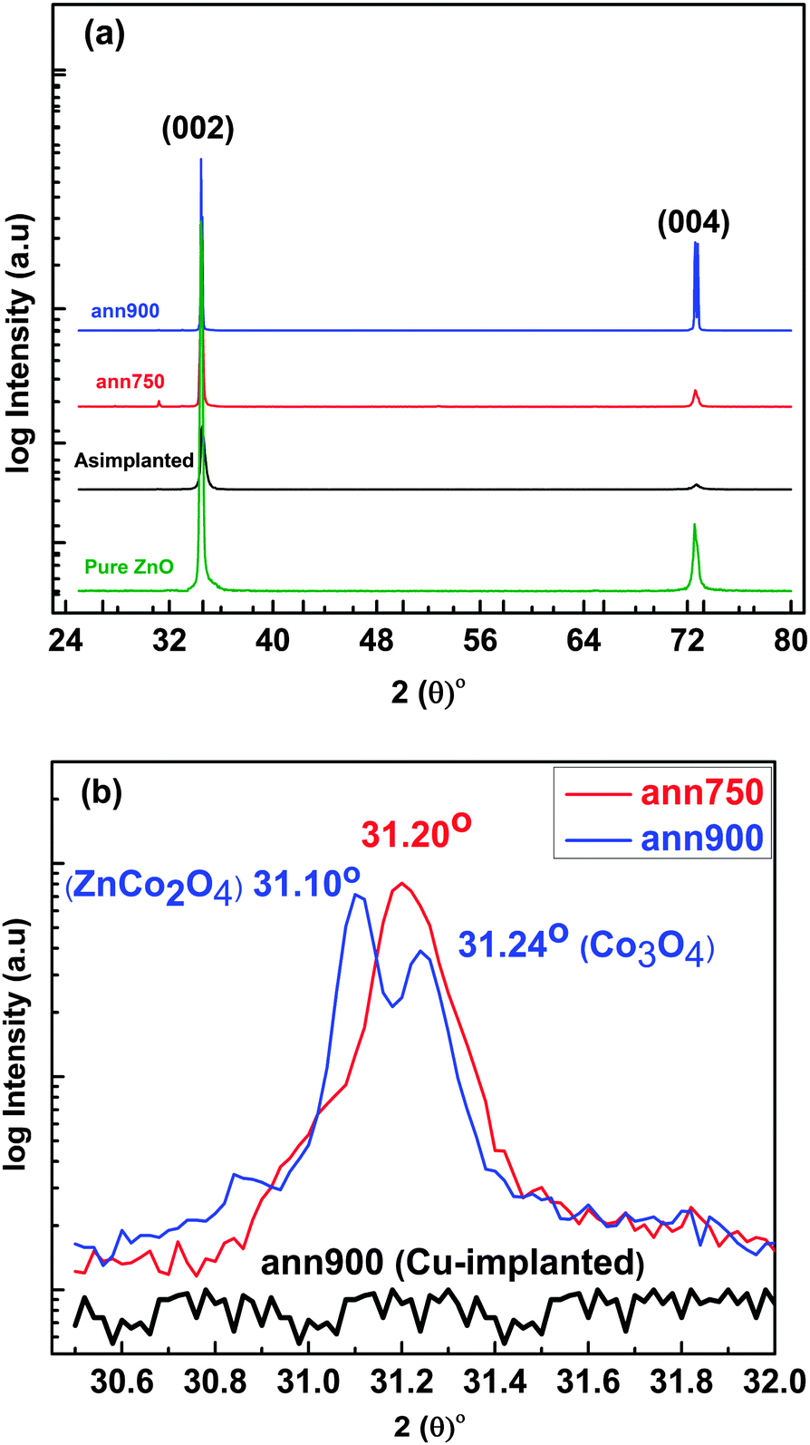 | ||
| Fig. 1 (a) XRD patterns for the Co-implanted ZnO single crystal samples and the (b) slow scan XRD from 30.5° to 32° for the as-Co-implanted sample, the 750 °C and 900 °C annealed Cu-implanted ZnO single crystals. | ||
Thus, the observed new peaks for the Co-implanted samples (which are below the typical (100) ZnO reflection peak around 31.8°) and the absence of the (100) ZnO reflection in the Cu-implanted ZnO single crystals suggest the presence of secondary phases in our 900 °C annealed Co-implanted samples. The two new peaks in the slow scan XRD (Fig. 1(b)) correspond to the spinel phases of ZnCo2O4 (JCPDS# 021069) and Co3O4 (JCPDS# 781970). Although the high temperature annealing of our ann900 sample successfully shows two secondary phases, we are unable to separate all the potentials phases for the 750 °C annealed sample (ann750) and the broad XRD peak at 31.20° is interpreted as the superposition of the corresponding thermally induced evolving phases. These evolving phases are effectively well separated on the basis of their response towards IS (will be discussed in Section 3.3). Within the detection limit of XRD, signatures related to the Co cluster and CoO are not identified. Our SIMS results (not shown here) illustrate that in the as-implanted sample, Co ions are unevenly distributed to a depth of ∼200 nm from the surface with an average concentration of ∼0.60%, and this distribution profile remains unaffected even after annealing at high temperatures (900 °C).
In order to study the electronic structure of the substituted Co at the Zn site and the influence of the possible defects, PL measurements were performed at 10 K for the as-Co-implanted ZnO single crystal and the post-implantation annealed samples. The dominant peak around 3.35 eV for both the un-implanted (inset of Fig. 2(a)) and the Co-implanted single crystals is related to the excitons bound to the neutral donors.27 After annealing the Co-implanted sample at 900 °C, the intensity of this band edge emission decreases, showing the introduction of annealing induced defects in this sample. PL spectra of the ann750 and ann900 samples show broad green luminescence at 2.40 eV in the visible region and it increases considerably for the ann900 sample. The origin of the green luminescence is still controversial and is attributed to VO, VZn and a Cu impurity.28,29 To get a deeper insight into the annealing induced green luminescence, we compared the PL spectra of the implanted samples with the un-implanted pure ZnO single crystals (inset of Fig. 2(a)). The green luminescence was also found in both the as-grown pure ZnO single crystals and the 900 °C annealed Co-implanted sample. Furthermore, our pure ZnO thin films annealed at 750 °C and 900 °C grown by pulsed laser deposition technique show a similar green luminescence pattern (not shown here). Our observation regarding the green luminescence for single crystals and thin films suggests that the observed green luminescence is irrelevant to Co but rather an intrinsic property of single crystal and thin films. The additional peak at 1.884 eV in the implanted samples is related to the electronic transitions between the d-levels of the isolated Co2+ ions in a tetrahedral symmetry of oxygen atoms which shows the Co substitution at the Zn site (CoZn).30,31
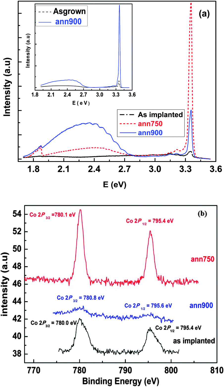 | ||
| Fig. 2 (a) PL spectra for the Co-implanted samples at 10 K. Inset shows the PL spectra for the un-implanted samples. (b) Room temperature XPS spectra of the Co 2p peaks in the Co-implanted samples. | ||
XPS has been employed to study the chemical state of Co ions in implanted samples. Fig. 2(b) shows the XPS Co 2p core level spectra. The positions and the Full Width at Half Maximum (FWHM) of peaks are presented in Table 1. For the as-implanted sample, the Co 2p3/2 peak (780.0 eV) accompanied by the Co 2p1/2 peak (795.4 eV) with ΔE = 15.4 ± 0.1 eV indicates the existence of Co2+.32,33 Although the XPS spectra show no detectable traces of CoO and Co clusters within the detection limit of XPS, the possible existence of CoO traces cannot be ignored completely due to the existence of Co2+. For the ann750 sample, the positions of the Co2p3/2, Co 2p1/2 peaks and the ΔE = 15.3 ± 0.03 eV are almost the same as that of the as-implanted sample. However, the Co peak intensities of the ann750 sample is much higher, indicating a more isolated character of the Co2+ ions. In the ann900 sample, the ΔE (= 14.80 ± 0.16 eV) is smaller than that of the as implanted and the ann750 samples. This could be due to the simultaneous existence of Co3O432 and ZnCo2O4 phases in the ann900 sample, as revealed by the XRD result. The observed main Co 2p peak position in the ann900 sample also has a much broader FWHM (∼9 eV), plausibly implying the co-existence of the Co2+ and Co3+ states in these Co3O4 and ZnCo2O4 phases. In these spinel type phases, photoelectron signals from different oxygen coordination with the Co2+ and Co3+ states are intermingled and these are normally indistinguishable by XPS.34 Furthermore, Hays et al.33 and Petitto et al.35 reported that in Co3O4 spinel type phase, the Co2+ and Co3+ oxidation states are thermodynamically stable and inter-convertible at the crystal surface, but under ambient conditions Co3O4 is the most stable phase.
| Co 2p3/2 (eV) | FWHM | Co 2p1/2 (eV) | FWHM | ΔE (eV) | |
|---|---|---|---|---|---|
| As-implanted | 780.0 ± 0.07 | 2.14 | 795.4 ± 0.03 | 2.32 | 15.4 ± 0.10 |
| ann750 | 780.1 ± 0.04 | 1.37 | 795.4 ± 0.01 | 1.45 | 15.3 ± 0.03 |
| ann900 | 780.8 ± 0.15 | 6.68 | 795.6 ± 0.17 | 8.67 | 14.8 ± 0.16 |
3.2 Magnetic properties
The room temperature M–H curve in Fig. 3 shows that the as-grown ZnO single crystal exhibits no hysteresis. For the as-implanted, ann750 and ann900 samples, FM is clearly observed in the low field region (−800–800 G). Beyond this particular field, unsaturated magnetization trends at the higher field are correlated to the paramagnetic behaviour originating from the pronounced surface spin disorder.36 The observed magnetization is converted from emu units to μB/Co on the basis of the Co concentration obtained by SIMS measurement. The resultant magnetic parameters are tabulated in Table 2, indicating that the ann750 sample has lower values of remanence magnetization (Mr), saturation magnetization (Ms) and magnetic moment (μB/Co) compared to the ann900 sample. All the implanted samples show much smaller values of μB/Co (0.2–0.5 μB/Co) than those of high-spin Co2+ (3 μB/Co) and metallic Co (1.73 μB/Co).37 The observed weak magnetic saturation not only shows the absence of metallic Co but also intimates that the ferromagnetic signal in these samples is mainly from the direct Co2+–Co2+ interactions. Furthermore, it is also observed that the intrinsic defects are not related to the magnetic properties of the implanted samples. Although the broad green luminescence peak in the as-grown pure ZnO single crystal (inset of Fig. 2a) indicates the existence of intrinsic defects, no FM is observed in this sample showing the irrelevance of the intrinsic defects to the magnetic properties. These observations show that weak FM in these samples is not of single origin, instead different behaviours are in competition with each other. To make a deeper analysis and explore the possible origin of the weak FM, IS under magnetic field was performed on these samples.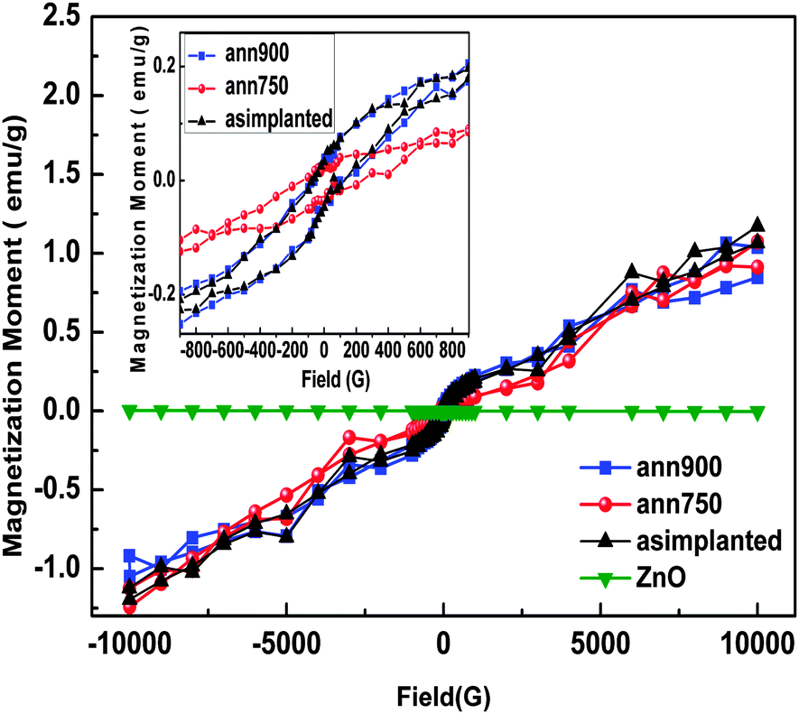 | ||
| Fig. 3 Room temperature field vs. magnetization (M–H) graph for the Co-implanted and the pure ZnO single crystals. Inset shows the magnetization in the low field region. | ||
| Mr (emu g−1) | Ms (emu g−1) | Hc (G) | μ (μB/Co) | |
|---|---|---|---|---|
| As-implanted | 0.05 | 0.19 | 151.16 | 0.478 |
| ann750 | 0.02 | 0.09 | 151.16 | 0.213 |
| ann900 | 0.04 | 0.19 | 110.00 | 0.463 |
3.3 Impedance spectroscopy
In impedance measurements Z′′ (the imaginary part of the impedance) vs. Z′ (the real part of the impedance) plots generally appear in semicircular forms and the widths and heights of these semicircles are correlated with the resistive and capacitive behaviours of the material, respectively. Different surrounding environments of the existing multiple phases and defects within the materials under observation sometime generate more than one relaxation processes. Therefore, it is a common knowledge during impedance (i.e. Z′′ vs. Z′ plots) data analysis that it is hard to spread out the competing phases when the difference in relaxation times among phases is two orders of magnitudes or less.17,18 Different phases with approximately similar or comparable relaxation times for the involved carriers in conduction confer more depressed semicircular arcs.The depressed semicircular arcs normally depict a smaller height than width, i.e. Zmax′′ < 1/2{Zmax′ − Zmin′}, where Zmax′′ represents the vertical height of the semicircle and Zmax′ and Zmin′ represent the real axis intercepts at the lower and higher frequency sides, respectively. The difference Zmax′ − Zmin′ (diameter of the semicircle) provides the total resistance of the sample under consideration.17,18 Another more general observation in the impedance measurement is that sometimes the semicircular arc does not pass through the origin due to other arcs having higher relaxation frequencies beyond the measurement limit.17 In this situation we have to utilize other available formalisms for the better resolution of the competing relaxation processes.
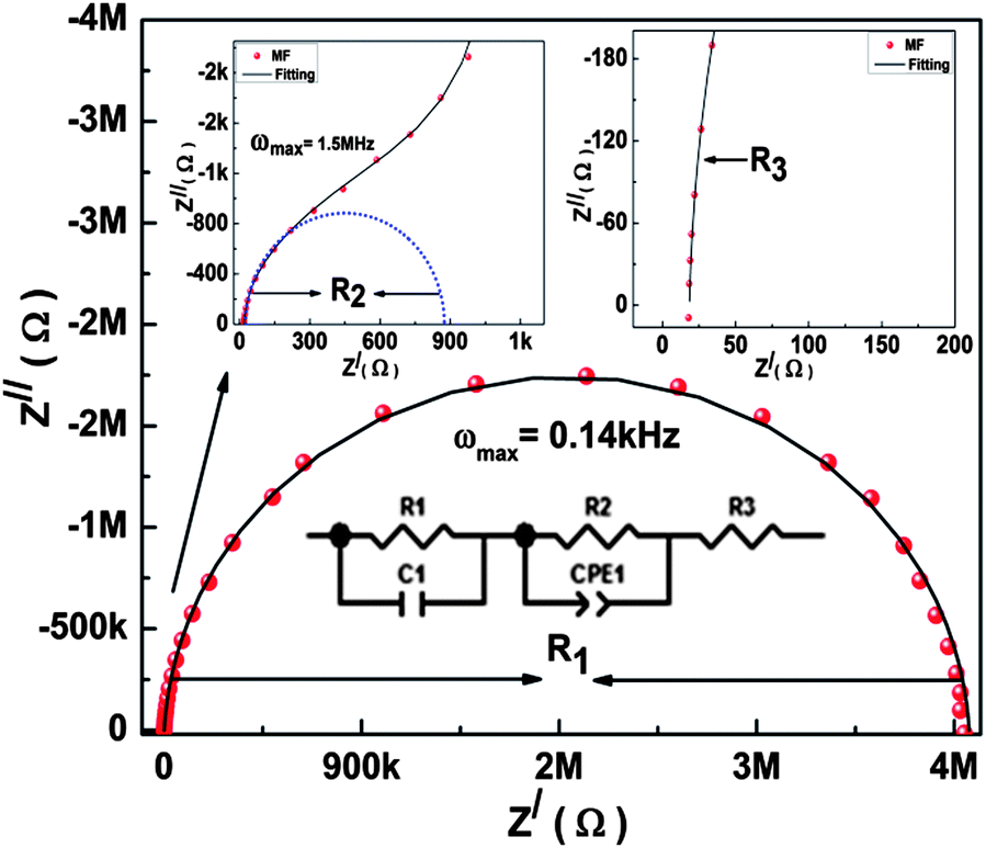 | ||
| Fig. 4 Impedance plane plots for the ann750 sample under the magnetic field (MF). Frequency increases from right to left. The left and right insets are the enlarged views of the Z′ = 0–1 kΩ region and the Z′ = 0–200 Ω region, respectively. The dots, solid lines, and dashed lines represent the data, the resultant fitted lines and the contributions from the individual elements, respectively. The fitted model is also included. | ||
For phases with very low resistance, only part of the corresponding arc can be seen in the Z′′–Z′ plot if the ωmax is outside the available frequency range.20 In the right inset of Fig. 4, the non-zero intercept at the low Z′ region (i.e. the high frequency) indicates the presence of an arc with ωmax well above the maximum measurement frequency (i.e. 107 Hz). This implies that three phases are identified in the Z′′–Z′ plot of the ann750 sample measured with the magnetic field. A similar three-phase behaviour is found in the same sample after removal of the magnetic field.
In the Z′′ vs. Z′ plots of the ann750 sample measured under the null magnetic field conditions as shown in Fig. 5 and that of the ann900 sample under the different magnetic environments (not shown here), two components are visually distinguished by the distorted arc and the non-zero intercept at high frequency.
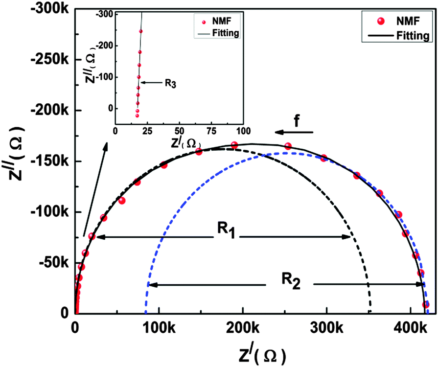 | ||
| Fig. 5 Impedance plane plots for the ann750 sample under no magnetic field (NMF). Arrows show the increasing direction in frequency. The inset shows the enlarged view of the Z′ (= 0–100 Ω) region (i.e. high frequency region). The dots, solid lines, and dashed lines represent the data, resultant fitted lines and contributions from the individual elements, respectively. | ||
Non-linear fitting was performed on all the Z′′ vs. Z′ data using ZVIEW source code with the equivalent circuit model comprising of parallel R-CPE elements (associated with the corresponding phases) connected in series. The constant phase element CPE is given by:
| C = (CPE)1/nR(1−n)/n |
The factor n has the limiting cases n = 1 and n = 0 associated with the pure capacitive and pure resistive behaviours, respectively.18 Based on the chi-squares obtained from the trial fitting and the heterogeneity that is usually present in the post-ion-implantation annealed samples, CPE instead of capacitance is used in the equivalent circuit. This is also confirmed by the large depression angles as tabulated in Table 3. The depression angles for the ann750 and ann900 samples were estimated by fitting the impedance plane plot using ZVIEW software. We observe high values of the depression angle (∼16°) under no magnetic field conditions for a single semicircle of the ann750 sample. This high depression angle indicates the presence of inhomogeneity due to the existence of the intermingled multiple phases. The value of the depression angle falls to ∼9° for small semicircles and ∼6–8° for large semicircles for the same samples in the magnetic field and the null magnetic field conditions, respectively. This indicates improved phase stability with the application of the magnetic field; this explains the observation of the three clear phases in the impedance plan plots of this sample. For the ann900 sample we observe a high depression angle (∼13°) indicating again the presence of diverse phases with very close relaxation times.
| ann750 | ann900 | |||||
|---|---|---|---|---|---|---|
| NMF | MF | AMF | NMF | MF | AMF | |
| a D.A. is depression angle, C1 = small semicircle at higher frequency, C2 = large semicircle at low frequency. | ||||||
| R 1 (Ω) | 2.31 × 10⁵ | 3.71 × 10⁶ | 2.21 × 10⁵ | 1.53 × 10⁵ | 3.24 × 10³ | 2.41 × 10³ |
| C 1 (F) | 6 × 10⁻¹⁰ | 1 × 10⁻⁹ | 10 × 10−10 | 1 × 10⁻⁹ | 10 × 10−10 | 1.2 × 10⁻⁹ |
| R 2 (Ω) | 1.3 × 10⁵ | 980.1 | 2.01 × 10³ | 4.6 × 10⁵ | 621.3 | 8.71 × 10³ |
| CPE2 | 6 × 10⁻¹⁰ | 2.1 × 10⁻⁹ | 1.9 × 10⁻⁹ | 1.2 × 10⁻⁹ | 8 × 10⁻¹⁰ | 9.4 × 10⁻¹⁰ |
| n 2 | 0.99 | 0.97 | 0.98 | 0.98 | 0.99 | 0.98 |
| C 2 (F) | 7 × 10⁻⁹ | 2 × 10⁻⁹ | 2 × 10⁻⁹ | 9.4 × 10⁻¹⁰ | 7 × 10⁻¹⁰ | 7 × 10⁻¹⁰ |
| R 3 (Ω) | 18.28 | 18.13 | 18.93 | 19.65 | 34.47 | 23.61 |
| R t (Ω) | 3.6 × 10⁵ | 3.7 × 10⁶ | 2.3 × 10⁵ | 6.1 × 10⁵ | 3.9 × 10³ | 1.1 × 10³ |
| D.A.a | 16.20 | 9.36C1 | 9.45C1 | 5.93 | 13.35 | 13.56 |
| 6.18C2 | 8.024C2 | |||||
The Z′′–Z′ plots were firstly fitted with the three-component model (i.e. the (R1CPE1)(R2CPE2)(R3CPE3) model), although in some of the Z′′–Z′ plots only two phases could be clearly visually separable. Processes with relaxation times differing less than two orders of magnitude cannot be clearly visually separable in the Z′′–Z′ plot.17,18 We have also attempted to use the two-component model on those Z′′–Z′ plots which only showed two clearly distinguishable arcs, but we found that the chi-squares were significantly inferior than those obtained by the three-component fitting. Our preliminary three-component fittings on all the samples and measuring magnetic environments have two findings, namely (1) all the fitted n1 values are effectively close to unity showing a more capacitive behaviour of the associated phase, and (2) the third component is more conducting and showing a metallic type behaviour. We thus dropped capacitance from the third RC component and carried out the final fittings using the (R1C1)(R2CPE2)(R3) model. The best fitted results of all the parameters are tabulated in Table 3. The fitted resistances R1, R2 and R3 are extracted and tabulated in Table 4 for further discussion.
| R 1 (Co3O4) | R 2 (ZnCo2O4) | R 3 (CoZn) | R t | |
|---|---|---|---|---|
| ann750 (NMF) | 2.31 × 10⁵ | 1.3 × 10⁵ | 18.28 | 3.6 × 10⁵ |
| MF | 3.71 × 10⁶ | 980.1 | 18.13 | 3.7 × 10⁶ |
| AMF | 2.21 × 10⁵ | 2.01 × 10³ | 18.93 | 2.3 × 10⁵ |
| ann900 (NMF) | 1.53 × 10⁵ | 4.6 × 10⁵ | 19.65 | 6.1 × 10⁵ |
| MF | 3.24 × 10³ | 621.3 | 34.47 | 3.9 × 10³ |
| AMF | 2.41 × 10³ | 8.71 × 10³ | 23.61 | 1.1 × 10⁴ |
It is worthy to discuss the physical origins of the three phases identified in the IS measurements. VSM and XRD data as presented previously showed that the Co-cluster and pure Co2+ (like CoO) phases were absent in the present samples and that only the ZnCo2O4 and Co3O4 phases are revealed by the XRD results. The Spinel type ZnCo2O4 has been reported to have high resistivity with hole/electron mediated ferromagnetic/antiferromagnetic behaviors.38,39 The Co3O4 is conventionally regarded as paramagnetic with Neil temperature TN ∼ 30 K and has a normal spinel structure.40,41
Regardless of the annealing temperatures and the measuring magnetic environment, R3 is always as low as ∼15–30 Ω. This is attributed to the CoZn site because of its metallic behaviour. The possibility of Co clustering is ruled out due to the low observed magnetic moments in the magnetization data. Park et al.42 also reported that Co clustering would occur in Zn1−xCoxO with x > 0.12. Paramagnetic materials have a magnetic dipole moment owing to the incomplete cancellation of the electron spin or orbital magnetic moments. Without an external magnetic field, these moments are randomly oriented and thus resulting in a zero net magnetization. Under a magnetic field, these magnetic dipoles are individually aligned without any mutual interaction.43 During IS measurements in the null magnetic field and magnetic field conditions, we observe no appreciable change in R3 in all the annealed samples. Even after retreating from the magnetic field (AMF), R3 seems to possess its original value. The lacking response of the R3 towards the magnetic environments shows that the phase is of metallic type with paramagnetic properties.
As shown in Table 4, R2 has a similar magnetic behaviour for both the 750 °C and 900 °C annealed samples. The R2 value under no magnetic field conditions is ∼105 Ω. It drops significantly to ∼1 × 10³ Ω under the magnetic field. It then slightly increases from 103 to 104 Ω after the magnetic field is removed. In antiferromagnetic materials the spin moments of the neighbouring atoms or ions align in exactly the opposite directions. The solid as a whole thus retains no net magnetic moment.43 Dietl et al.44 reported that the ferromagnetic behaviour in Co-doped ZnO is due to the uncompensated spins at the surface of the antiferromagnetic Co-rich wurtzite (Zn, Co)O phase distributed in the Co-poor (Zn, Co)O paramagnetic matrix. In our case, with the applied magnetic field, the uncompensated surface spins align accordingly. This reduces the carrier scattering and thus leads to a relatively lower impedance value. When the magnetic field is removed, these uncompensated surface spins stay aligned permanently but most of the bulk spins retain their original anti-parallel orientation and reintroduce the higher value of resistance to this phase. We thus attribute this phase to the ZnCo2O4 phase.
For the 750 °C annealed sample, the R1 value under no magnetic field conditions is ∼105 Ω. Under the applied magnetic field, it increases slightly to ∼106 Ω, and then returns to ∼105 Ω after the magnetic field is removed. This observation is similar to a typical superparamagnetic behaviour. One of the plausible explanations is that Ar annealing relaxes the structure by freeing the adsorbed species on the phase boundary. This would allow the dangling bonds to support the frustrated spin disorder. Under the magnetic field, frustrated surface spins randomly oriented in a spin-glass-like structure would act as a trap for charge carriers, and thus create a higher resistance.45 After the removal of the magnetic field, this phase regains its original lower resistance. The exact origin of this superparamagnetic phase in the ann750 sample is not unambiguously known. In the ann750 samples, three component phases are competing, namely the R1(Co3O4) with superparamagnetic behaviour, the R2(ZnCo2O4) phase with a ferromagnetic surface and antiferromagnetic core, and finally the R3(CoZn) phase having a paramagnetic behaviour. The total resistance (Rt) of the ann750 sample shows the superparamagnetic type behavior which indicate an appreciable influence of the superparamagnetic R1(Co3O4) phase to the overall ferromagnetic behaviour; therefore we observed relatively lower values of Mr, Ms, μB/Co and a higher value of Hc for this sample as discussed previously.
For the ann900 sample, the response of R1 towards the magnetic field is different. The R1 value (∼105 Ω) under no magnetic field decreases to ∼103 Ω when the measurements are taken under the magnetic field. It then maintains effectively the same value after the magnetic field is removed showing its ferromagnetic nature. The pure paramagnetic Co3O4 cannot account for this ferromagnetic behaviour, but the formation of a ferromagnetic region in the Co3O4 phase could offer a plausible explanation. Martin-Gonzalez et al.46 observed the surface reduction of the Co3O4 particle to ferromagnetic CoO in the ZnO–Co3O4 mixture. A similar formation of a CoO ferromagnetic region has likely occurred on the surface of the Co3O4 phase. The superparamagnetic R1 phase observed in the 750 °C sample as discussed in the last paragraph could be the intermediate phase for this ferromagnetic phase formed at 900 °C annealing. This is compatible with the XRD observation in which the Co3O4 peaks remained merged in a broad peak after 750 °C annealing but it is only clearly separable after 900 °C annealing (see Fig. 1(b)). The total resistance (Rt) of the ann900 sample shows a ferromagnetic type behaviour indicating the appreciable influence of the ferromagnetic R1(Co3O4) phase on the overall magnetic behaviour of this sample.
![[thin space (1/6-em)]](https://www.rsc.org/images/entities/b_char_2009.gif) f) and loss (Z′′ vs. logf) formalisms.
Up to now we have discussed all the samples in the different environments using impedance plane plots and established the link among possible secondary phases and best fitted resistances. Impedance plane plots normally exploit the most resistive phase and the less resistive part is either suppressed or may stretch out the measuring range. The electrode and interface due to the space charge effects have high resistances. The high electrode resistance if present in the sample may overlap with the other high resistive phases, and can generate an ambiguous result. For the successful attachment of the fitted results to the observed phases, it is therefore necessary to rule out the possibility of the electrode effects. In the following section, both the loss and modulus formalisms will be discussed simultaneously to justify the existence of the secondary phases and the exclusion of the contact effect.
f) and loss (Z′′ vs. logf) formalisms.
Up to now we have discussed all the samples in the different environments using impedance plane plots and established the link among possible secondary phases and best fitted resistances. Impedance plane plots normally exploit the most resistive phase and the less resistive part is either suppressed or may stretch out the measuring range. The electrode and interface due to the space charge effects have high resistances. The high electrode resistance if present in the sample may overlap with the other high resistive phases, and can generate an ambiguous result. For the successful attachment of the fitted results to the observed phases, it is therefore necessary to rule out the possibility of the electrode effects. In the following section, both the loss and modulus formalisms will be discussed simultaneously to justify the existence of the secondary phases and the exclusion of the contact effect.
Complex impedance and complex modulus are the two general electrical parameters in the IS approach to differentiate the intermingled electronic process associated with a substantial mixture of highly conductive and highly resistive suspended phases. Complex impedance (Z*) and complex modulus (M*) can be calculated using the following relations of Z* = Z′ + jZ′′ and M* = M′ + jM′′ = jωC0Z*, where Z′′/M′ and Z′′/M′′ are the real and imaginary parts of impedance and modulus, respectively, ω = 2πf, is the angular frequency, j2 = −1 and C0 is the empty cell capacitance. For a parallel RC circuit, we have the following relations for Z′ = R/1 + (ωRC)2, Z′′ = ωCR2/[1 + (ωCR)2] and M′ = ω2RCC0/[1 + (ωCR)2], M′′ = ωRC0/[1 + (ωCR)2].17,18 The loss spectrum (Z′′ vs. log(f)) in the impedance formalism reveals the most resistive part of the material as Z′′ ∼ CR2, where R and C represent the resistance and capacitance of the associated phase. Modulus formalism (M′′ vs. log(f)) highlights the bulk properties of the material under consideration by suppressing the electrode/interfacial polarization effects due to their large capacitance as M′′ ∼ 1/C2R2. In this approach, plot of M′′ vs. log![[thin space (1/6-em)]](https://www.rsc.org/images/entities/char_2009.gif) f demonstrates a maximum at a characteristic frequency in the conduction process of the relevant phase.47–49
f demonstrates a maximum at a characteristic frequency in the conduction process of the relevant phase.47–49
For the ann750 sample, we observed a noticeable impedance behaviour as shown in Fig. 6. In the absence of the magnetic field, only one distorted and asymmetric peak in both the loss and modulus spectra is observed. This broad distorted peak is correlated to the competing effects of the ZnCo2O4 and Co3O4 phases having comparable resistances (in consonance with the XRD result where superposition of two competing phases is interpreted as a single peak). However, the application of the magnetic field introduces the secondary phases by transforming the single peak into two different peaks (inset of Fig. 6). The loss spectrum shows only one peak related to the most resistive, i.e. the Co3O4 phase in this case. On the other hand, two well resolved peaks appear in the modulus formalism under the magnetic field and after the removal of the magnetic field. The lower and higher frequency peaks are coupled with the relaxation of dipoles in the low and the high conductivity Co3O4 and ZnCo2O4 phases, respectively. The low conductivity Co3O4 peaks at ∼20 Hz (MF) and ∼700 Hz (AMF) appear, respectively, in both the M′′ vs. logf and Z′′ vs. logf plots (inset of Fig. 6.), implying that there are no electrode and interfacial effects. It is because of the fact that the electrode/interfacial effects if present would appear as the most dominant peak in the loss spectrum (Z′′ vs. logf) due to their high resistance.
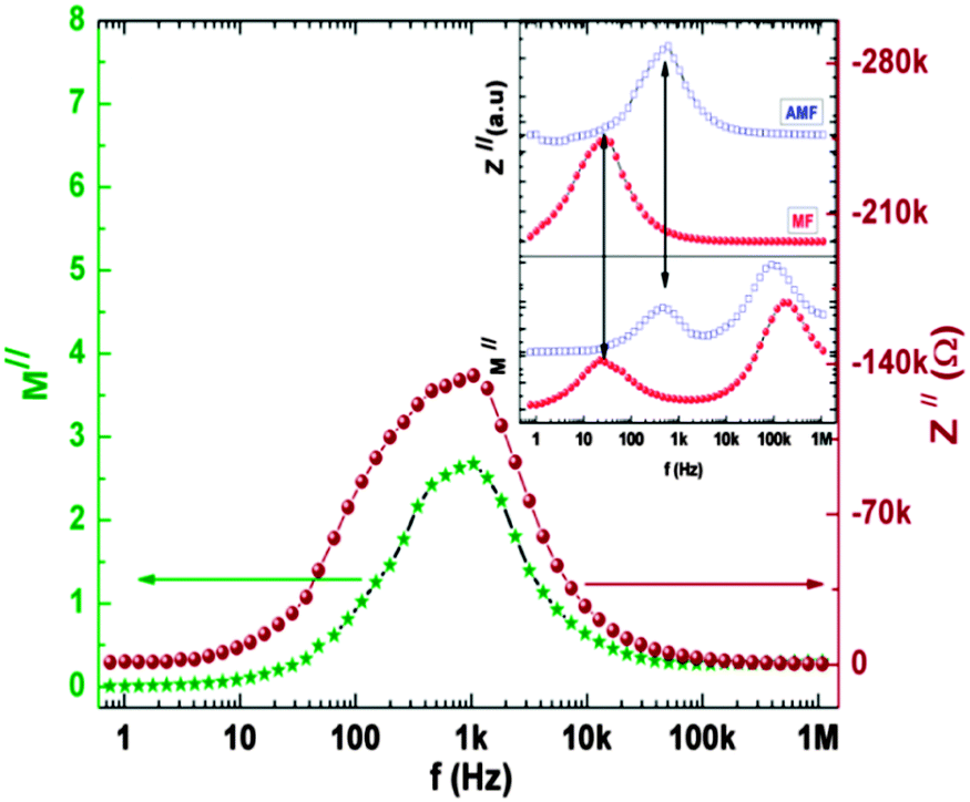 | ||
| Fig. 6 The M′′ vs. log(f) and Z′′ vs. log(f) plots for the ann750 sample measured in the null magnetic field condition (NMF). The inserts show the M′′ vs. log(f) and Z′′ vs. log(f) plots measured within the magnetic field (MF) and after the removal from the magnetic field (AMF) for the same sample. | ||
By comparing these findings with previous studies carried out by Wikberg et al.50 and Ney et al.51 on Co-implanted ZnO single crystals, we successfully identified two spinel type secondary phases embedded in the ZnO host matrix by combining the impedance results with the other spectroscopic techniques. In both these studies, the Co ions (100 keV energy) were implanted into ZnO single crystals at room temperature with higher flux values and lower annealing temperatures compared to our case. No spinel type secondary phase was observed in the XRD pattern of the as-implanted and annealed samples, instead a Co2Zn alloy was observed.50 However it was argued that for the consistent explanation of the observed ferromagnetic behaviour at least one ferromagnetic (ferrimagnetic) component with transition temperature closer to room temperature is still required.50 One of the possible reasons for their complete failure in filtering out all the potential phases inside the sample is related to the low annealing temperatures of 800 °C50 and 450 °C.51 At these low annealing temperatures, thermally induced phases may be superimposed and remain undetected by XRD, similarly to our case for the ann750 sample, but these phases were effectively well separated by IS. The other possibility is the utilization of the high implantation dose in the above-discussed studies. At comparatively low defect concentrations, the efficiency of the ZnO surface on dynamic annealing may be higher leading to the more relaxed surface. The free ZnO surface acting as a defect sink at low fluence (similar to our case with fluence ∼1 × 1015 cm−2) provides support to the dopant ions to find enough time and energy to settle down to form the spinel type secondary phases. On the other hand, at higher fluence, the defect sink properties of the surface might be degraded or dominated by the high defect concentration, leading to a more uniformly damaged surface.15,52 The damaged surface with higher fluence (∼5 × 1016 cm−2 in the above discussed study50) might provide high energy to the dopant ions to form Co2Zn alloy along with the formation of other small size secondary phases that remain unnoticed by XRD due to the detection limit problem.
4. Conclusions
We have studied the secondary phases in Co-implanted ZnO using a comprehensive spectroscopic approach. PL and XPS results indicate the signature of the Co2+ state and its substitution at tetrahedrally coordinated Zn-sites. XRD patterns for the ann900 sample reveal the ZnCo2O4 and Co3O4 phases after heat treatment. The impedance data are fitted with the three components (R1C1)(R2CPE2)(R3) model within the null magnetic field, under magnetic field and after removal of the magnetic field environments for the ann750 and ann900 samples. IS results successfully differentiated the magnetic ZnCo2O4 and Co3O4 secondary phases in the Co-implanted ZnO as well as the paramagnetic CoZn phase. The coinciding of the observed relaxation frequencies of both the loss and modulus spectra eliminate electrode interferences and show the real picture of the material. The observed FM in each sample is not of single origin but instead it is the joint effect of the secondary phases embedded in the paramagnetic host matrix. We suggest that the secondary phases are present all the time in the annealed samples but their thermal stability and mix relaxation frequencies limits their resolution. Although, the Co concentration is low in our samples, we have shown that impedance spectroscopy measurements under a magnetic field is a powerful tool to deliberately identify the intermingled phases when they are present with different conductivities.Acknowledgements
The work presented here was supported by the RGC, HKSAR under the GRF (HKU703612P) and SEG_HKUST03, as well as HKU Seed Funding Program for Basic Research (201111159037), and the National Natural Science Foundation of China (No. 61205037). We are also thankful to the EMMG, PINSTECH, Nilore, Islamabad, Pakistan for providing the IS facilities.Notes and references
- T. Dietl, H. Ohno, F. Matsukura, J. Cibert and D. Ferrand, Science, 2000, 287, 1019 CrossRef CAS.
- K. Sato and H. Katayama-Yoshida, Jpn. J. Appl. Phys., 2000, 39, L555 CrossRef CAS.
- K. Ueda, H. Tabata and T. Kawai, Appl. Phys. Lett., 2001, 79, 988 CrossRef CAS PubMed.
- C. D. Pemmaraju, R. Hanafin, T. Archer, H. B. Braun and S. Sanvito, Phys. Rev. B: Condens. Matter Mater. Phys., 2008, 78, 054428 CrossRef.
- G. Ciatto, A. Di Trolio, E. Fonda, P. Alippi, A. M. Testa and A. A. Bonapasta, Phys. Rev. Lett., 2011, 107, 127206 CrossRef CAS.
- S. Yin, M. X. Xu, L. Yang, J. F. Liu, H. Rösner, H. Hahn, H. Gleiter, D. Schild, S. Doyle, T. Liu, T. D. Hu, E. Takayama-Muromachi and J. Z. Jiang, Phys. Rev. B: Condens. Matter Mater. Phys., 2006, 73, 224408 CrossRef.
- T. C. Kaspar, T. Droubay, S. M. Heald, M. H. Engelhard, P. Nachimuthu and S. A. Chamber, Phys. Rev. B: Condens. Matter Mater. Phys., 2008, 77, 201303(R) CrossRef.
- C. N. R. Rao and F. L. Deepak, J. Mater. Chem., 2005, 15, 573 RSC.
- Z. Jin, T. Fukumura, M. Kawasaki, K. Ando, H. Saito, T. Sekiguchi, Y. Z. Yoo, M. Murakami, Y. Matsumoto, T. Hasegawa and H. Koinuma, Appl. Phys. Lett., 2001, 78, 3824 CrossRef CAS PubMed.
- A. Ney, T. Kammermeier, K. Ollefs, S. Ye, V. Ney, T. C. Kaspar, S. A. Chambers, F. Wilhelm and A. Rogalev, Phys. Rev. B: Condens. Matter Mater. Phys., 2010, 81, 054420 CrossRef.
- A. Ney, M. Opel, T. C. Kaspar, V. Ney, S. Ye, K. Ollefs, T. Kammermeier, S. Bauer, K. W. Nielsen, S. T. B. Goennenwein, M. H. Engelhard, S. Zhou, K. Potzger, J. Simon, W. Mader, S. M. Heald, J. C. Cezar, F. Wilhelm, A. Rogalev, R. Gross and S. A. Chambers, New J. Phys., 2010, 12, 013020 CrossRef.
- S. Zhou, K. Potzger, G. Talut, H. Reuther, J. von Borany, R. Grötzschel, W. Skorupa, M. Helm, J. Fassbender, N. Volbers, M. Lorenz and T. Herrmannsdorfer, J. Appl. Phys., 2008, 103, 023902 CrossRef PubMed.
- S. O. Kucheyev, J. S. Williams, C. Jagadish, J. Zou, C. Evans, A. J. Nelson and A. V. Hamza, Phys. Rev. B: Condens. Matter, 2003, 67, 094115 CrossRef.
- A. Yu. Azarov, A. Hallén, X. L. Du, P. Rauwel, A. Yu. Kuznetsov and B. G. Svensson, J. Appl. Phys., 2014, 115, 073512 CrossRef PubMed.
- M. A. Myers, M. T. Myers, M. J. Genera, J. H. Lee, L. Shao and H. Wang, Appl. Phys. Lett., 2012, 101, 112101 CrossRef PubMed.
- J. C. A. Huang and H. S. Hsu, Appl. Phys. Lett., 2005, 87, 132503 CrossRef PubMed.
- J. R. Macdonald, Impedance Spectroscopy Emphasing Solid Materials and Systems, Wiley, New York, 1987 Search PubMed.
- E. Barsoukov and J. R. Macdonald, Impedance Spectroscopy Theory, Experiments and Applications, John Wiley, New Jersey, 2nd edn, 2005 Search PubMed.
- D. C. Sinclair and A. R. West, J. Appl. Phys., 1989, 66, 3850 CrossRef CAS PubMed.
- D. C. Sinclair, T. B. Adams, F. D. Morrison and A. R. West, Appl. Phys. Lett., 2002, 80, 2153 CrossRef CAS PubMed.
- P. B. Macedo, C. T. Maynihan and R. Bose, Phys. Chem. Glasses, 1972, 13, 171 CAS.
- V. Rovenzano, L. P. Boesch, V. Volterra, C. T. Moynihan and P. B. Macedo, J. Am. Ceram. Soc., 1972, 55, 492 CrossRef PubMed.
- H. S. Hsu, J. C. A. Huang, S. F. Chen and C. P. Liu, Appl. Phys. Lett., 2007, 90, 102506 CrossRef PubMed.
- J. F. Ziegler, J. P. Biersack and U. Littmark, The Stopping and Range of Ions in Solids, Pergamon, New York, 1985 Search PubMed.
- X. Penga, J. Xub, H. Zanga, B. Wangb and Z. Wang, J. Lumin., 2008, 128, 297 CrossRef PubMed.
- G. K. Mani and J. B. B. Rayappan, J. Alloys Compd., 2014, 582, 414 CrossRef CAS PubMed.
- P. A. Rodnyi and I. V. Khodyuk, Opt. Spectrosc., 2011, 111, 776 CrossRef CAS.
- E. Biegger, M. Fonin, U. Rüdiger, N. Janßen, M. Beyer, T. Thomay, R. Bratschitsch and Yu. S. Dedkov, J. Appl. Phys., 2007, 101, 073904 CrossRef PubMed.
- H. S. Kang, J. S. Kang, J. W. Kim and S. Y. Lee, J. Appl. Phys., 2004, 95, 1246 CrossRef CAS PubMed.
- V. V. Strelchuk, V. P. Bryksa, K. A. Avramenko, P. M. Lytvyn, M. Ya. Valakh, V. O. Pashchenko, O. M. Bludov, C. Deparis, C. Morhain and P. Tronc, Semicond. Phys., Quantum Electron. Optoelectron., 2011, 14, 31 CAS.
- J. W. Quilty, A. Shibata, J. Y. Son, K. Takubo, T. Mizokawa, H. Toyosaki, T. Fukumura and M. Kawasaki, Phys. Rev. Lett., 2006, 96, 027202 CrossRef CAS.
- J. F. Moulder, W. F. Stickle, P. E. Sobol and K. D. Bomben, Handbook of X-ray Photoelectron Spectroscopy, Perkin–Elmer, Eden Prairie, 1992 Search PubMed.
- J. Hays, K. M. Reddy, N. Y. Graces, M. H. Engelhard, V. Shutthanandan, M. Lue, C. Xu, N. C. Giles, C. Wang, S. Thevuthasan and A. Punnoose, J. Phys.: Condens. Matter, 2007, 19, 266203 CrossRef CAS PubMed.
- B. J. Tan, K. J. Klabunde and P. M. A. Sherwood, J. Am. Chem. Soc., 1991, 113, 855 CrossRef CAS.
- S. C. Petitto, E. M. Marsh, G. A. Carson and M. A. Langell, J. Mol. Catal. A: Chem., 2008, 281, 49 CrossRef CAS PubMed.
- M. Younas, M. Nadeem, M. Atif and R. Grossinger, J. Appl. Phys., 2011, 109, 093704 CrossRef PubMed.
- M. Ivill, S. J. Pearton, S. Rawal, L. Leu, P. Sadik, R. Das, A. F. Hebard, M. Chisholm, J. D. Budai and D. P. Norton, New J. Phys., 2008, 10, 065002 CrossRef.
- M. Dekkers, G. Rijnders and D. H. A. Blankb, Appl. Phys. Lett., 2007, 90, 021903 CrossRef PubMed.
- H. J. Kim, I. C. Song, J. H. Sim, H. Kim, D. Kim, Y. E. Ihm and W. K. Choo, J. Appl. Phys., 2004, 95, 7387 CrossRef CAS PubMed.
- P. Dutta, M. S. Seehra, S. Thota and J. Kumar, J. Phys.: Condens. Matter, 2008, 20, 015218 CrossRef.
- M. Hamdani, R. N. Singh and P. Chartier, Int. J. Electrochem. Sci., 2010, 5, 556 CAS.
- J. H. Park, M. G. Kim, H. M. Jang, S. Ryul and Y. M. Kim, Appl. Phys. Lett., 2004, 84, 1338 CrossRef CAS PubMed.
- B. D. Cullity, Introduction to Magnetic Materials, Addison-Wesley, Readings, Massachusetts, 2nd edn, 1978 Search PubMed.
- T. Dietl, T. Andrearczyk, A. Lipińska, M. Kiecana, M. Tay and Y. Wu, Phys. Rev. B: Condens. Matter Mater. Phys., 2007, 76, 155312 CrossRef.
- M. Younas, M. Atif, M. Nadeem, M. Siddique, M. Idrees and R. Grossinger, J. Phys. D: Appl. Phys., 2011, 44, 345402 CrossRef.
- M. S. Martin-Gonzalez, J. F. Fernandez, F. Rubio-Marcos, I. Lorite, J. L. Costa-Kramer, A. Quesada, M. A. Banares and J. L. G. Fierro, J. Appl. Phys., 2008, 103, 083905 CrossRef PubMed.
- P. B. Macedo, C. T. Maynihan and R. Bose, Phys. Chem. Glasses, 1972, 13, 171 CAS.
- V. Rovenzano, L. P. Boesch, V. Volterra, C. T. Moynihan and P. B. Macedo, J. Am. Ceram. Soc., 1972, 55, 492 CrossRef PubMed.
- I. M. Hodge, K. L. Ngai and C. T. Moynihan, J. Non-Cryst. Solids, 2005, 351, 104 CrossRef CAS PubMed.
- J. M. Wikberg, R. Knut, A. Audren, M. Ottosson, M. K. Linnarsson, O. Karis, A. Hallén and P. Svedlindh, J. Appl. Phys., 2011, 109, 083918 CrossRef PubMed.
- V. Ney, S. Ye, T. Kammermeier, A. Ney, H. Zhou, J. Fallert, H. Kalt, F. Y. Lo, A. Melnikov and A. D. Wieck, J. Appl. Phys., 2008, 104, 083904 CrossRef PubMed.
- M. T. Myers, S. Charnvanichborikarn, L. Shao and S. O. Kucheyev, Scr. Mater., 2012, 67, 65 CrossRef CAS PubMed.
| This journal is © the Owner Societies 2014 |