 Open Access Article
Structure reconstruction of TiO2-based multi-wall nanotubes: first-principles calculations†
A. V.
Bandura
,
R. A.
Evarestov
and
S. I.
Lukyanov
*
Department of Quantum Chemistry, St Petersburg State University, 26 Universitetsky Avenue, Peterhof, St Petersburg 198504, Russia. E-mail: lsiq80@hotmail.com
First published on 1st May 2014
Abstract
A new method of theoretical modelling of polyhedral single-walled nanotubes based on the consolidation of walls in the rolled-up multi-walled nanotubes is proposed. Molecular mechanics and ab initio quantum mechanics methods are applied to investigate the merging of walls in nanotubes constructed from the different phases of titania. The combination of two methods allows us to simulate the structures which are difficult to find only by ab initio calculations. For nanotube folding we have used (1) the 3-plane fluorite TiO2 layer; (2) the anatase (101) 6-plane layer; (3) the rutile (110) 6-plane layer; and (4) the 6-plane layer with lepidocrocite morphology. The symmetry of the resulting single-walled nanotubes is significantly lower than the symmetry of initial coaxial cylindrical double- or triple-walled nanotubes. These merged nanotubes acquire higher stability in comparison with the initial multi-walled nanotubes. The wall thickness of the merged nanotubes exceeds 1 nm and approaches the corresponding parameter of the experimental patterns. The present investigation demonstrates that the merged nanotubes can integrate the two different crystalline phases in one and the same wall structure.
1. Introduction
Titania nanotubes (NTs) have demonstrated a wide range of potential applications such as the surface modification of biomedical implants,1 photoanodes of dye-sensitized solar cells,2 anodes in lithium-ion batteries,3,4 and photocatalysts to decompose water and organic compounds.5,6There are a variety of techniques of titania NTs synthesis. Three of these methods are most commonly used: assisted-template method, anodization and hydrothermal treatment.1 The first of these can be used to fabricate formally single walled (SW) nanotubes, although the walls of most NTs consist of several layers, so actually they can be considered as multi-walled (MW) nanotubes. Titania NTs produced by this method have lengths from 1.5 to 6.0 μm, inner diameters of 10–100 nm, outer diameters between 140 and 200 nm and wall thicknesses of around 10–120 nm.1
Hydrothermal treatment also provides the formation of multilayered or multi-walled NTs.7–9 The obtained tubular objects are observed to have wall thicknesses of 2.5 nm, inner diameters of 2–10 nm, outer diameters of 8–12 nm and their height varies from 10 to 600 nm. The NTs fabricated in one of these studies include 3–5 layers separated by 0.5 nm.8 The synthesized double-walled (DW) nanotubes of TiO2-B (bronze-phase titanium dioxide) structure exhibit a gap of about 1.0 nm between two adjacent surfaces.3 Mogilevsky et al.8 found that the crystalline structure of the investigated titania NTs corresponded to the anatase phase. These nanotubes were formed by rolling the layers perpendicular to the [001] direction8 with the central axis oriented along the [010] direction. At the same time, the walls of the TiO2 NTs obtained by hydrothermal treatment7 consist of two layers and the exact structure of these layers is not sufficiently clear. The possible compositions are H2Ti3O7, H2Ti2O4(OH)2, or H2Ti4O9·H2O.7 The crystalline structure of trititanic acid (H2Ti3O7) nanotubes was analyzed.3 Chen et al.3 have proposed that the layered scroll-like NTs were formed by rolling (100) titanate sheets around the [010] axis. However, Ma and co-workers10 suggested that TiO2-based NTs produced by the hydrothermal procedure are constructed from lepidocrocite HxTi2−x/4□x/4O4 (x ∼ 0.7, □: vacancy) sheets. Finally, W. Wang and co-workers11 based on their experimental results suggested a mechanism of anatase NT growth by means of the hydrothermal method used in the three studies.3,10,11 According to W. Wang et al.,11 the resulting anatase NTs have the [010] direction as the central axis. Hence, there are at least three different interpretations of the crystal structure (titanate,3 lepidocrocite10 and anatase11) of TiO2 NTs obtained by one and the same hydrothermal method.
Using the sol–gel method, Y. Q. Wang and co-workers12 synthesized anatase NTs with an inner diameter of around 5 nm and an outer diameter of about 9 nm. High-resolution transmission electron microscopy studies showed that these NTs possess a layered anatase structure with (101) layer spacing of about 0.71 nm. The tube axis was determined to be along the [010] direction of the anatase phase.
Anodic oxidation of metallic Ti with the oxide formation produces TiO2 nanotubular arrays or layers. Depending on the applied electrolyte, the resulted NTs may be multi-walled (mainly double-walled) or single walled.13,14 The wall thickness of SW NTs varies from 10 nm to 70 nm, their inner diameter varies from 70 to 620 nm, outer diameter from 15 nm to 820 nm, and the length of NTs ranges from ∼100 nm up to 1 mm.1,13–15 The transmission electron microscopy images of DW NTs demonstrate that NT walls consist of two regions: an outer shell and an inner shell of the tube.13–16 The DW NTs have an outer shell thickness of ∼25 nm or 30 nm. The thickness of the inner shell varies from a few nm to 50 nm, the total diameter of these NTs is in the range of 160–230 nm and they have an inner pore diameter of about 70 nm. The tube length or the height of the DW NT array is 10–20 μm.2,13 Using anodic oxidation, DW NTs have also been prepared16 with the inner diameter of the outer shell equal to about 70 nm.
After annealing at 150–500 °C the DW and SW NTs transform into NTs with a crystalline anatase phase.1,13,14 Increasing the temperature to 800 °C leads to the conversion of the anatase structure to the rutile structure.13
Though a lot of experimental data on synthesized titania NTs have been obtained, these data are not sufficient for the development of unambiguous theoretical models, accurately describing the chemical structure and morphology of the TiO2 based NTs. Most of the modern theoretical models of rolled-up NTs are created through the folding of crystalline layers or sheets.17 However this procedure provides NTs with thin (monolayer) walls only (see paragraph below). As a result, the most of the theoretical calculations are performed for rolled-up NTs with a wall thickness less than 0.3 nm. Nevertheless, the minimum wall thickness of synthesized TiO2 NTs is about 2.5 nm.
At least two problems arise in the realistic modelling of inorganic NTs. The first problem is connected to the slab rolling-up procedure. A large tension appears within the NT due to the difference between the circumferences of the inner and outer surfaces of the NT. Let us suppose that the maximal overstrain δ leading to the breaking of some transverse (approximately oriented perpendicular to the tube axis) chemical bonds is 0.1 (10% is a reasonable admissible change of chemical bond length). This means that the ratio of the bond length s′ in the outer surface of the NT to its normal value s in the central (unstrained) shell, s′/s, should be less than 1.1: s′/s = 1 + δ < 1 + 0.1. On the other hand, if we use the rolling procedure, s′/s = 2π(R + w/2)/(πD), where R = NT radius, D = diameter, and w = NT wall thickness. Consequently, we have δ = w/D < 0.1. The breaking of this relation can lead to the disruption of chemical bonds and disintegration of the NT walls. Therefore, it is necessary to provide alternative methods for the formation of NTs with dimensions close to those in the experimentally observed patterns where the ratio w/D is normally about 0.3 or higher. For example, recently, an alternative method18 has been proposed to construct faceted NTs. The authors of this work18 cut a hole in the TiO2 faceted nanowire crystalline sample to obtain NTs with a wall thickness approaching 1 nm. The theoretical studies of ZnO faceted NTs cut from a bulk crystal are also discussed in a recent review.19
The second problem is connected to scanning of the potential energy surface of multi-atomic systems. In many cases it is necessary to apply molecular mechanics (MM) or molecular dynamics (MD) methods to get the most stable atomic configuration. Any algorithm used in both quantum mechanical (QM) or MM structure optimization procedure enables reaching of the local minimum on the potential energy surface (PES) that is nearest to the initial state. Generally, the PES of a multi-atomic system is very complex, and the result of optimization is very dependent on the choice of the initial structure. Our experience showed that a force-field PES used in MM is smoother than a QM PES. Because of this, the MM optimization permits us to reach a favorable state which is more remote from the initial state than the nearest QM local minimum from the given initial state. Also, due to very fast computations, MM and MD methods provide an opportunity to scan a lot of initial states. Obviously, the relative stability of the MM states differs from that of the QM states. However, this difference is not critical for a carefully adjusted force-field. In the majority of cases, use of the MM output structure as the initial structure for QM optimization produces a new stable state. Hence, the combination of MM modelling and ab initio calculations provides a more effective PES scan. Note, this strategy is not new and has been applied in a large number of studies of different complex systems (see, for example, ref. 20).
In this work we consider a new method of theoretical modelling of polyhedral SW NTs with sufficiently thick walls which is based on the merging of walls of coaxial MW NTs. At an initial stage the “ideal” MW NT is formed by combining two or more rolled-up SW NTs folded from a thin layer with similar chiralities and different diameters. At the second stage an optimization process of the MW NT structure is performed. Depending on the strength of the interactions between the constituent SW NTs and the interwall distance, the whole system may retain the MW structure (that is, be stable) or may undergo a crucial transformation to the SW NT. The proposed technique originated from our previous studies of MW NTs. Thus, in our recent paper21 titania coaxial DW NTs rolled up from hexagonal layers were investigated. The stability of high-symmetry DW NTs depends mainly on the difference ΔRNT between the radii of the inner and outer SW NTs and on the diameter of the inner shell (DinNT). The results21 indicate that the DW TiO2 NTs with zigzag and armchair chiralities are unstable at ΔRNT < 4.1 Å and ΔRNT < 4.8 Å, respectively. (Note, the radius RNT of rolled-up TiO2 SW NT can be estimated as the radius of the middle Ti subshell.) Continuing this study, here we consider the DW and MW TiO2 NTs with low ΔRNT values providing significantly strong interactions between the constituents of MW NTs. The transformations of MW NTs caused by the interwall interactions are examined and the results of these transformations are analyzed. Molecular mechanics has been used for the preliminary optimization of the DW NT structure. In the majority of considered cases the SW constituents of DW NT have merged into a NT with consolidated single wall (CSW NT) upon MM optimization. The quantum mechanical structure optimization was performed starting both from the initial and from the MM optimized structures. Due to computational reasons we have preserved the symmetry rotation axis of order 4–8 during the optimization process in most cases. It should be noted that the relaxing of this condition may increase the NT stability.
In the next section we describe the simulation method used in our study. The obtained results are presented and discussed in the Results and discussion section and conclusions are given in the final section.
2. Computational details
All the QM calculations were performed within the periodic density functional theory (DFT) methods implemented in the CRYSTAL09 computer code.22,23 This code uses the localized Gaussian-type functions as the basis for the expansion of crystalline orbitals as the linear combination of atomic orbitals (LCAO). An all-electron basis set24 for O atoms was chosen. The CRENBL25 small-core pseudopotentials and the corresponding basis set were used for Ti atom. It is well known that in the LCAO calculations of crystals the basis set of a free atom has to be modified as the diffuse functions cause numerical problems because of the large overlap with the core functions of the neighboring atoms in a dense-packed crystal.17 The diffuse exponents of valence s, p and d-orbitals have been optimized26 for the stable anatase phase of bulk titania.The NT monoperiodic rototranslational symmetry is adopted for our NT calculations as it is implemented with NANOTUBE and HELIX options in the CRYSTAL09 code.23 The LCAO basis, which is used in the CRYSTAL09 code, allows one to describe both 1D nanotubes and 2D sheets, unlike the plane wave (PW) basis requiring spurious periodicity introduction. Indeed, to restore the 3D periodicity in the PW calculations, the NT supercell is artificially introduced: the NTs are placed into a square array with an inter-tube distance of 10–30 Å. The convergence of the results obtained using PW calculations depends on the artificial inter-tube interactions, therefore, additional computational efforts should be provided to ensure their negligibility. This artefact is certainly absent in our LCAO calculations.
The shrinking factor for 1D Brillouin zone summation was taken as 12. Calculations were considered as converged only when the total energy obtained in the self-consistency procedure differed by less than 10−7 a.u. in two successive cycles. Coordinates of all atoms in the 1D unit cells were allowed to relax when performing the optimization procedure until the root-mean-square forces on the atoms were less than 0.003 eV Å−1 in bulk and slab systems, and less than 0.03 eV Å−1 in NTs.
A hybrid Hartree–Fock–Kohn–Sham approach with PBE0 exchange–correlation functional27 was applied in most of the QM computations. This method reproduces the bulk properties of anatase and rutile phases of TiO2 in good agreement with experiment. Thus, for the anatase phase we have obtained the lattice parameters a = 3.781 Å (3.782 Å), c = 9.531 Å (9.502 Å), and the dimensionless parameter for the position of oxygen atom u = 0.207 (0.208). The calculation results for the bulk rutile phase: a = 4.587 Å (4.587 Å), c = 2.961 Å (2.954 Å), and u = 0.305 (0.305). (The experimental values for the anatase and rutile28 phases at 15 K are given in parentheses.) The same exchange–correlation functional and basis set were used in our previous studies21,26,29 of SW and DW TiO2 NTs with different morphology.
Before performing the present study we have analyzed the possibility of including the empirical dispersion correction in our calculations of the TiO2 nanosystems. It is known that addition of the dispersion C6 term to the atomic interaction potential may be important for the correct description of molecular and layered crystals, self-assembled nanotubes and nanostructures.30–33 We start with the parameterization30 of the PBE0-D method which reproduces the correct order of the formation energies as well as the cell constants of TiO2 rutile and anatase polymorphs. Analyzing the potential energy contributions we have revealed that the damping function (used to avoid near-singularities for small interatomic distances) admits the value of 1/2 at the equilibrium Ti–O bond distance. This means that the proposed C6 term introduces a huge contribution at the distance where the DFT description is quite perfect and no dispersion correction is needed. Our attempt to reduce the C6 contributions at low distances by modification of the damping function failed. So, we have concluded that the empirical correction used in the DFT-D method affects strongly the DFT description at small distances and is capable of distorting the DFT PES and its derivatives with respect to atomic positions in solid oxides. However, we need to calculate the bulk, slab and NT properties in the same approximation. That is why we decided to use the regular PBE0 exchange correlation functional. This choice also allows us direct comparison of the new results with the data of our previous studies of single- and double-walled TiO2 NTs.21,26,29 Nevertheless, we have performed DFT-D calculations for several selected systems. We have applied the PBE0-D method using the original Conesa parameterization31 with a minor modification. The value of 0.5 was adopted for the scaling s0 parameter. This value provides the better rutile and anatase cell constants than the original value of 0.75 in the case of the PBE0 functional. The obtained results are briefly discussed in Section 3.1 below.
The molecular mechanics approach has been used as the auxiliary method to obtain stable NT structures. For MM simulations we have used the GULP computer code.34 The MM optimization is disparately faster than quantum mechanics calculation and permits a more detailed study of the potential energy surface in some special cases (see discussion in the Introduction section). In our MM simulations we have used the force-field of Matsui and Akaogi35 which was developed to reproduce the structure of TiO2 polymorphs. Note, the dispersion contributions are explicitly taken into account by this force-field. It was shown previously36 that it is sufficiently correct in predicting surface relaxation of the TiO2 rutile phase. Moreover, our preliminary calculations have evidenced that it can reproduce the general structure of TiO2 SW NTs and provide accurate values of their strain energies obtained in quantum mechanics calculations. Further calculations demonstrated that the Matsui and Akaogi potential is able to predict the overall structure of NTs with the consolidated walls. Nevertheless, all the force-field generated structures were taken just as the input for the further quantum mechanical optimization. Therefore, all the data reported in this paper were ultimately calculated by an ab initio method.
3. Results and discussion
3.1. Nanotubes folded from layers with hexagonal morphology
The symmetry and structure of SW NTs can be simply described using so-called layer folding,37 which means the construction of cylindrical surfaces of NTs by rolling up 2D-periodic crystalline nanolayers (sheets or slabs). The resulting NT is defined by the translation vector Lt = l1a + l2b and the chiral vector Rc = n1a + n2b, where l1, l2, n1 and n2 are integers, and a and b are the translation vectors of the 2D lattice. The NT of chirality (n1,n2) is obtained by folding the layer in a way that the chiral vector Rc becomes the circumference of the NT. The orthogonality relation RcLt = 0 has to be used to define the NT chiralities (n1,n2) compatible with the initial 2D lattice periodicity.37,38We have investigated a large set of MW NTs folded from (111) 3-plane slab (Fig. 1a) cut from a fluorite-like TiO2 crystal (space group Fm![[3 with combining macron]](https://www.rsc.org/images/entities/char_0033_0304.gif) m). This cubic structure can really exist in a metastable phase of bulk titania under extremely high pressure.39 The (111) layer of this phase has a hexagonal morphology (with cadmium iodide structure). It was used for the construction of SW26,29 and DW21 NTs in our previous studies. Below we report the results for the selected DW and MW NTs stacked up from SW NTs with hexagonal morphology. Only the armchair and zigzag chiralities have been considered here for the SW constituents.
m). This cubic structure can really exist in a metastable phase of bulk titania under extremely high pressure.39 The (111) layer of this phase has a hexagonal morphology (with cadmium iodide structure). It was used for the construction of SW26,29 and DW21 NTs in our previous studies. Below we report the results for the selected DW and MW NTs stacked up from SW NTs with hexagonal morphology. Only the armchair and zigzag chiralities have been considered here for the SW constituents.
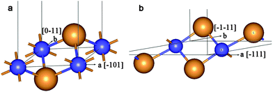 | ||
| Fig. 1 Unit cell of 2D lattice of 3-plane (111) fluorite layer (a) and 6-plane (101) anatase layer (b). Large orange balls = O2− anions and small blue balls = Ti4+ cations. | ||
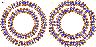
The final structure of the MW NT depends on the initial interwall distance ΔRNT. The values of ΔRNT were calculated for MW NTs constructed by stacking two or three SW constituents which were separately optimized by the ab initio method. The results of MM and QM calculations indicate that there are two stable configurations for each of the two initially cylindrical armchair DW TiO2 NTs: (12,12)@(18,18) and (10,10)@(15,15). The first stable configuration is a high symmetry coaxial DW NT and the second is a NT with the consolidated wall produced by the merging of the SW constituents of the initial DW NT (Fig. 2).
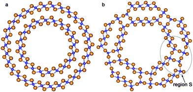 | ||
| Fig. 2 Cross section images of TiO2 NTs: (a) optimized structure of DW NT (10,10)@(15,15); (b) CSW NT obtained from DW NT (10,10)@(15,15). See Fig. 1 for legend. | ||
We have selected the four above-mentioned systems to test the influence of the C6 dispersion term on the calculated results. We have found that dispersion correction31 does not noticeably change the optimized geometry of NTs, but it affects the values of the formation, strain, and binding energies considerably (see ESI†). Thus, the binding energies of both double- and consolidated single-walled NTs are lowered by about 10 kJ mol−1 relative to the PBE0 values. However, since this shift is almost constant, C6 correction does not influence significantly the relative stability of the four considered NTs and it could not alter the conclusions of the preceding paragraph. So, the introduction of the dispersion correction via the PBE0-D method (if it would be accepted) should not considerably affect the conclusions of this study.
The values of ΔRNT for the initial coaxial structure of the DW NTs (12,12)@(18,18) and (10,10)@(15,15) are 4.9 Å and 4.1 Å, respectively. In the case of the DW NT (12,12)@(16,16) the interwall distance is less than or equal to 3.3 Å. As a result of this small ΔRNT, it becomes very unstable and the ab initio structural optimization leads to a break of its external wall. However, Fig. 3a indicates that the MM optimization, followed by the QM optimization of (12,12)@(16,16) (with preservation of the 4-fold rotation axis) leads to the CSW NT.
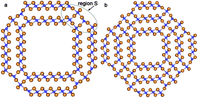 | ||
| Fig. 3 Cross section images of TiO2 SW NTs with the consolidated wall obtained from different initial coaxial cylindrical NTs with hexagonal morphology: (a) from DW (12,12)@(16,16); (b) from TW (8,8)@(12,12)@(16,16). See Fig. 1 for legend. | ||
The transformation of a DW NT into a CSW NT occurs through a break of the Tiin–Oin bonds of the inner and the Tiout–Oout bonds of the outer SW constituents and subsequent formation of new Ti–O bonds. As it follows from Fig. 2b and 3a the two SW constituents are sewn together by pairs of bridging oxygen atoms. One of the oxygen atoms belonging to the same pair comes from the outer shell and the other oxygen comes from the inner shell. The comparison of Fig. 4a and b demonstrates that two combined bridging pairs are forming an element of the rutile(110) slab. All three initial DW NTs, (12,12)@(18,18), (10,10)@(15,15), and (12,12)@(16,16), have the chiralities of the constituents with the greatest common divisors equal to 6, 5 and 4, respectively. Because of this the resulted SW NTs have the rotational (rototranslational) axes of order 6, 5 and 4 (Fig. 2b and 3a), respectively and the corresponding polyhedral shape.
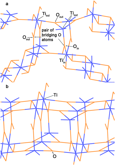 | ||
| Fig. 4 (a) The detailed view of the region S in Fig. 2b. (b) The view of (110) 6-plane rutile TiO2 slab along the [001] direction. Orange lines = O2− anions and blue lines = Ti4+ cations. | ||
The rutile-like structure of the bridging elements becomes more prominent in the case of the merged triple-walled (TW) TiO2 NT (8,8)@(12,12)@(16,16). Both MM and QM optimizations lead to the merging of walls of the initially cylindrical TW NT with hexagonal morphology (Fig. 3b). The consolidated wall of this SW NT consists of the planar residues of outer, inner and middle shells of the initial hexagonal layer structure which are connected by the broad rudiments of the rutile(110) slabs. It is possible to distinguish at least three layers (containing 9 (110) atomic planes) of the rutile structure inside the SW NT’s consolidated wall.
An important property of the CSW NT is the wall thickness. Due to irregularity of walls it depends on the direction in which the thickness is measured. In this work we accept the conventional definition of the wall thickness: this is the distance between the atom (oxygen) most remote from the NT axis and the nearest atom (oxygen) to the NT axis projected to the direction of measurement, which must be specially defined for each kind of NT. The mentioned surface oxygen atoms should lie close to the indicated direction. In the cylindrical NT the wall thickness measurement should be performed along the diameter. If flat sectors exist in the inner and/or outer shell, the measurement should be performed along the normal to one or both surface planes. Obviously, the different directions can give the different wall thicknesses. Thus, in the CSW NTs considered in Fig. 2 and 3 the wall thickness of the elements of the rutile slab structure is minimal. The maximal wall thickness corresponds to the hexagonal residues of inner and outer shells.
In Table 1 the structural and energetic properties of the investigated NTs are given. The values of the formation energy, Ef, strain energy, Estr, and binding energy, Ebind, were calculated according to the following equations:
| Nanotube |
E
f
![[thin space (1/6-em)]](https://www.rsc.org/images/entities/char_2009.gif)
|
E
str
![[thin space (1/6-em)]](https://www.rsc.org/images/entities/char_2009.gif)
|
E
bind
![[thin space (1/6-em)]](https://www.rsc.org/images/entities/char_2009.gif)
|
w, Wall thickness/Å | ΔRNT![[thin space (1/6-em)]](https://www.rsc.org/images/entities/char_2009.gif) d/Å d/Å |
N
NT
![[thin space (1/6-em)]](https://www.rsc.org/images/entities/char_2009.gif)
|
||
|---|---|---|---|---|---|---|---|---|
| kJ mol−1 |
w
min
![[thin space (1/6-em)]](https://www.rsc.org/images/entities/char_2009.gif)
|
w
max
![[thin space (1/6-em)]](https://www.rsc.org/images/entities/char_2009.gif)
|
||||||
| a The definitions of energy parameters are given in the text. b w max and wmin are the maximum and minimum values of the CSW NT wall thickness calculated according to the conventional definition discussed in the text. c The wall thickness of the SW constituent of the DW NT with optimized configuration. d ΔRNT is an interwall distance discussed in the text. e N NT is the number of formula units in the 1D unit cell of the NT. | ||||||||
| Armchair | ||||||||
| (12,12)@(18,18) | DW NT | 47.5 | 3.9 | −3.5 | 2.0c | 2.0c | 4.9 | 60 |
| CSW NT | 48.5 | 4.9 | −2.5 | 3.9 | 7.9 | |||
| (10,10)@(15,15) | DW NT | 53.1 | 9.5 | −1.1 | 1.9c | 1.9c | 4.1 | 50 |
| CSW NT | 44.5 | 0.9 | −9.7 | 3.4 | 7.3 | |||
| (12,12)@(16,16) | CSW NT | 41.7 | −1.9 | −10.2 | 3.4 | 6.6 | 3.3 | 56 |
| (8,8)@(12,12)@(16,16) | CSW NT | 33.7 | −9.9 | −22.0 | 6.8 | 11.2 | 6.5 | 72 |
| Zigzag | ||||||||
| (16,0)@(24,0) | DW NT | 56.6 | 13.0 | 0.6 | 2.0c | 2.0c | 3.7 | 80 |
| CSW NT | 60.3 | 16.7 | 4.3 | 5.1 | 6.1 | |||
| (14,0)@(21,0) | CSW NT | 54.5 | 10.9 | −5.3 | 4.8 | 6.3 | 3.3 | 70 |
Here, ENT is the total energy of the SW, MW or CSW NT 1D unit cell obtained via the geometry optimization; Ebulk is the total energy of the optimized bulk (rutile) unit cell; NNT is the number of formula units in the 1D unit cell of the NT; Nbulk is the number of formula units in the bulk unit cell; Eslab is the total energy of the optimized slab 2D unit cell; Nslab is the number of formula units in the 2D unit cell of the slab; ESWNT,i is the total energy of i-th SW constituent calculated as a result of the geometry optimization, and n indicates the number of walls producing the initial MW NT. Strain energy, Estr, is the energy of NT formation from an optimized slab. Traditionally, Estr is used as the measure of the stability of single- and multi-walled rolled-up NTs. We list the values of Estr in Tables 1–3 mainly for the purpose of comparison with the results published earlier for rolled-up SW and DW NTs.21,26,29
It follows from Table 1 that the cylindrical (12,12)@(18,18) configuration and the corresponding CSW NT are both stable in regard to the SW constituents. Nevertheless, the former NT is slightly more stable than the latter, ΔEbind = 0.97 kJ mol−1. In contrast, in the case of NT (10,10)@(15,15) the CSW NT is preferable, ΔEbind = −8.57 kJ mol−1. As mentioned above, an ab initio optimized (12,12)@(16,16) coaxial structure could not be obtained. So, it can be concluded that a transformation from cylindrical DW NTs to polyhedral CSW NTs should occur in the interval of ΔRNT = 4.9–4.0 Å. The wall thickness in the resulting CSW NT varies in the interval of 6.6–7.9 Å.
As discussed above, the combined method of the MM and subsequent QM structure optimization allows us to simulate the SW NT with the consolidated wall initiating from the coaxial TW NT (8,8)@(12,12)@(16,16). The data on the binding energy in Table 1 indicate that this is the most stable SW NT with the maximum wall thickness among all considered NTs with hexagonal morphology. This CSW NT has a wall thickness of 11.2 Å which is five times thicker than the walls in the initial SW constituents (≈2 Å, see Table 1).
According to the present study, the mechanism of the NT wall merging depends on the initial DW NTs chirality. As discussed above, the armchair SW constituents are sewn together due to the appearance of the bridging oxygen atoms. However, the other way of merging is also possible. Note that each of the two constituents of the initial DW NT was obtained by folding of the 3-plane layer (Fig. 5a). The conglutination of the tube surfaces can be processed through the restoration of Ti–O bonds which were broken when slabs were cut from the bulk crystal. This is the way for the SW constituents to merge in the initial zigzag (16,0)@(24,0) and (14,0)@(21,0) DW NTs with the hexagonal morphology (Fig. 4). Since merging tubes have different diameters, the restoration of the maximum set of interwall Ti–O bonds corresponds to the restoration of all possible bonds from the outer surface of the inner SW. Nevertheless, as follows from Fig. 5b, only a half of the outer surface of the inner shell is involved in the Ti–O bonds restoration. The restored interlayer or interwall Ti–O bonds form several elements of the fluorite bulk structure. Similar to the armchair nanotubes the CSW NTs (16,0)@(24,0) and (14,0)@(21,0) consist of the residues of the corresponding SW NTs, but connected by the fluorite bulk structure elements in this case.
 | ||
| Fig. 5 Cross section images of TiO2 NTs with hexagonal morphology and zigzag initial chiralities. (a) Optimized structure of coaxial cylindrical DW (16,0)@(24,0); (b) SW NT with the consolidated wall obtained from DW (16,0)@(24,0). See Fig. 1 for legend. | ||
Zigzag CSW NTs (14,0)@(21,0) is stable in regard to the SW constituents, which initially were separated by ΔRNT = 3.3 Å (see Table 1). The DW NTs with narrower interwall gap cannot be obtained due to strong repulsion of oxygens in the internal surfaces. The DW NTs retain their coaxial cylindrical structure when ΔRNT is increased (Table 1).
In the case of zigzag chirality a merging transformation takes place at ΔRNT = 3.7–3.3 Å, that is lower than in the case of the armchair chirality (4.9–4.0 Å). The ΔRNT value of the initial DW NT (14,0)@(21,0) is close to that of the initial DW NT (12,12)@(16,16). The wall thickness in the CSW NT (14,0)@(21,0) is rather lower than the wall thickness in the CSW NT (12,12)@(16,16) (see Table 1). At the same time, the armchair CSW NT is more stable since its Ebind is almost twice as much as the Ebind of the zigzag CSW NT. Consequently, merging the SW constituents with the hexagonal morphology through the bridging oxygen bonds of the rutile slab elements is more favorable than merging these constituents through simply restoring the Ti–O bonds between the two layer's surfaces.
3.2. Nanotubes folded from layers of anatase, rutile and lepidocrocite
Experiments evidenced that the anatase structure (bulk space group I41/amd) is the most frequently observed in TiO2 NTs. In this study we have considered DW NTs folded from the anatase (101) 6-plane layer with (n1,n1)@(n2,n2) and (−n1,n1)@(−n2,n2) chiralities corresponding to the centered rectangular 2D unit cell of the (101) slab (Fig. 1b). The SW NTs rolled up from the indicated layer were studied in our previous works.29,38 The rutile structure (bulk space group P42mnm) is also reported for the experimentally found TiO2 NTs.13,40 To construct the initial structures of NTs with the rutile morphology we have used the rutile(110) 6-plane layer with (0,n1)@(0,n2) chiralities corresponding to the primitive rectangular 2D unit cell. It is known that the (110) surface is the most stable among the other possible rutile faces.41 Finally, the (001) 6-plane layer with lepidocrocite morphology has been used to fold the DW NTs with chirality (0,n1)@(0,n2).To investigate the formation of CSW NTs with the anatase morphology we have constructed a set of coaxial DW NTs with different initial interwall distance. We have found that merging become possible at ΔRNT below 7 Å. It is in accordance with the results of the above-mentioned authors12 who have observed the same value of the interwall distance in real anatase MW NTs.
In the present study two NTs with anatase morphology and chirality (8,8)@(12,12) have been obtained (Table 2): the first one is the cylindrical DW NT of very low relative stability, and the second one is the notably stable CSW NT. The data in Table 2 indicate that in the case of the (n1,n1)@(n2,n2) chirality the transition to a stable anatase-based CSW NT takes place at ΔRNT ≈ 6.6 Å. A similar transition has been found in the interval 5.7 Å ≥ ΔRNT ≥ 5.1 Å for the (−n1,n1)@(−n2,n2) chirality. In that way, the transitions to the stable CSW NTs in anatase-based NTs are achieved at greater ΔRNT than those transitions in fluorite-based NTs.
| Nanotube | E f | E str | E bind | w, Wall thickness/Å | ΔRNT/Å | N NT | ||
|---|---|---|---|---|---|---|---|---|
| kJ mol−1 | w min | w max | ||||||
| a The energetic and structural parameters are defined in Table 1. | ||||||||
| (8,8)@(12,12) | DW NT | 71.6 | 2.8 | 0.0 | 2.4 | 2.4 | 6.6 | 80 |
| CSW NT | 55.8 | −13.1 | −15.8 | 4.5 | 7.7 | |||
| (6,6)@(9,9) | CSW NT | 48.9 | −20.0 | −24.9 | 5.9 | 7.3 | 4.9 | 60 |
| (9,9)@(11,11) | CSW NT | 47.2 | −21.7 | −24.4 | 5.8 | 5.9 | 3.3 | 80 |
| (−10,10)@(−20,20) | DW NT | 77.8 | 8.9 | −1.8 | 2.5 | 2.5 | 5.7 | 120 |
| (−9,9)@(−18,18) | CSW NT | 64.0 | −4.9 | −16.9 | 5.6 | 6.6 | 5.1 | 108 |
| (−14,14)@(−21,21) | CSW NT | 52.8 | −16.1 | −24.9 | 5.7 | 6.5 | 3.9 | 140 |
Sewing together the anatase-based SW constituents of both considered chiralities occurs through the restoration of Ti–O bonds between folded layers. In contrast to the fluorite-based zigzag NTs, the structure of the anatase-based SW constituents of coaxial DW NTs provides a restoration of the majority of possible bonds from the outer surface of the inner SW constituents (compare Fig. 6 and 7). One can see in the selected region S in Fig. 6b and 7a that the restored Ti–O bonds form the characteristic elements of the anatase slab structure. The data in Table 2 indicate that the conventional wall thickness in the region of these elements varies in the interval 4.5–5.9 Å for all considered anatase-based CSW NTs. The wall thicknesses of anatase-based CSW NTs are close to the values of this parameter for fluorite-based NTs (see Tables 1 and 2). Unlike the fluorite-based CSW NTs, the anatase-based NTs of both chiralities do not exhibit the structural elements of an additional TiO2 bulk phase.
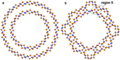 | ||
| Fig. 6 Cross section images of TiO2 NTs folded from the anatase layer: (a) optimized structure of coaxial cylindrical DW (8,8)@(12,12); (b) SW NT with the consolidated wall obtained from DW (8,8)@(12,12). See Fig. 1 for legend. | ||
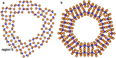 | ||
| Fig. 7 Cross section images of TiO2 NTs folded from the anatase layer. SW NTs with the consolidated wall obtained from the initial coaxial cylindrical DW NTs: (a) (6,6)@(9,9); (b) (−14,14)@(−21,21). See Fig. 1 for legend. | ||
The (110) rutile layers (Fig. 8a) have never been used before for the folding of NTs. It is known, however, that the rutile phase is the most stable among the other TiO2 phases, and its favorable (110) surface has been observed in different nanoobjects.13,40 This is the reason why we have included NTs with the rutile morphology in our study. In this case we have only considered the (0,n) chirality which was obtained by folding the (110) layer along the [−110] direction. The folding along the [001] direction leads to a great repulsion between the bridging oxygens on the inner tube surface, so the other possible chirality (n,0) is obviously less stable. The results of our calculations of selected DW and CSW NTs are listed in Table 3.
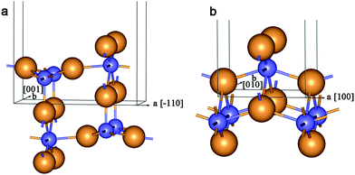 | ||
| Fig. 8 Unit cell of 2D lattice of 6-plane (110) rutile layer (a) and 6-plane (001) lepidocrocite layer (b). See Fig. 1 for legend. | ||
| Nanotube | E f | E str | E bind | w, Wall thickness/Å | ΔRNT/Å | N NT | ||
|---|---|---|---|---|---|---|---|---|
| kJ mol−1 | w min | w max | ||||||
| a The energetic and structural parameters are defined in Table 1. | ||||||||
| (0,10)@(0,20) | DW NT | 52.7 | 16.9 | −1.8 | 5.8 | 5.8 | 6.9 | 120 |
| (0,12)@(0,20) | CSW NT | 37.3 | 1.5 | −17.1 | 12.6 | 12.8 | 4.8 | 128 |
| (0,12)@(0,18) | CSW NT | 34.3 | −1.4 | −20.9 | 12.3 | 12.3 | 2.8 | 120 |
Optimization of the structure of rutile-based SW NTs with computationally treatable diameters leads to the breaking of a great deal of Ti–O bonds on the NT's outer surface. This is a consequence of the relatively large thickness of the rutile (110) 6-plane layer. The inner and outer SW constituents in Fig. 9a demonstrate such behavior. From Fig. 9b one can see that the interaction between the SW constituents of the DW NT provides a restoration of some bonds on the outmost surface upon merging. The transformation of rutile-based DW NTs to CSW NTs presumably takes place in the interval of ΔRNT = 7–5 Å.
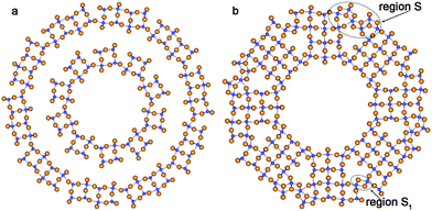 | ||
| Fig. 9 Cross section images of optimized structure of TiO2 NTs folded from the rutile layer. (a) Coaxial cylindrical DW (0,10)@(0,20); (b) SW NTs with the consolidated wall obtained from (0,12)@(0,20) DW NT. See Fig. 1 for legend. | ||
Merging of the rutile-based SW constituents of the NTs with (0,n) chiralities is performed through the restoration of Ti–O bonds between folded layers. The obtained CSW NTs consist of rutile nanorods combined by the sets of Ti–O bonds arranged as in the bulk fluorite structure (Fig. 9a and b). One can see in the selected regions S, S1 in Fig. 9b that the linking fragments of rutile nanorods were transformed into the elements of the bulk fluorite structure. As was discussed in the Introduction, the coexistence of the two crystalline phases is widely observed in the experimental studies of NTs.13,40 However, in the present study we have not observed the mixing of the rutile and anatase phases which is frequently reported in the experimental works. Instead of this we have found combinations of the fluorite and rutile structures.
The lepidocrocite morphology is one which has been considered as the probable structure of the TiO2 NTs with relatively thin walls.42 Because of this we have included two selected DW NTs with lepidocrocite morphology in our consideration (Fig. 10). For the construction of such NTs we have used the 6-plane (001) layer (Fig. 8b) of the hypothetical TiO2 phase of the space group 137 (P42/nmc). The chirality (n,0) only was investigated.
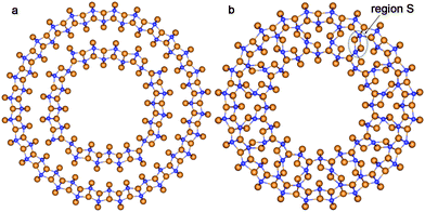 | ||
| Fig. 10 Cross section images of TiO2 NTs folded from the lepidocrocite layer. (a) (16,0)@(28,0) with optimized configuration; (b) SW NT with the consolidated wall obtained from the initial coaxial cylindrical DW NT (16,0)@(24,0). See Fig. 1 for legend. | ||
The consolidated wall NT was obtained through the merging of two SW constituents of the DW NT (16,0)@(24,0) rolled up from the TiO2 lepidocrocite (001) layers. However, this CSW NT is unstable relative to the corresponding DW NT, since the Ebind is positive (2.1 kJ mol−1). Nevertheless, the lepidocrocite-based CSW has a number of interesting properties. This NT keeps the cylindrical symmetry of the inner and outer shells after merging. Joining the two SW constituents is implemented through a break of Ti–O bonds in the inner SW shell and the creation of Ti–O bonds between the inner and outer SW constituents. From the selected region S in Fig. 10b one can see that, in contrast to the other considered NTs, the formation of the interwall bonds in lepidocrocite-based NTs creates new structure elements which cannot be found in the known TiO2 bulk phases.
3.3. Comparison of stability of nanotubes with consolidated walls
The anatase-based CSW NTs have the lowest values of Ebind, as can be seen from Tables 1–3. At the same time, the rutile-based CSW NTs have binding energies comparable with the energies of anatase-based NTs. The binding energies of fluorite-based CSW NTs generated from DW NTs are significantly higher. The stability of some fluorite-based CSW is comparable with that of the parent cylindrical DW NTs. However, Ebind = −22 kJ mol−1 of the CSW NT (8,8)@ (12,12)@(16,16) obtained from the TW NT is close to that of the rutile-based CSW NT (0,12)@(0,18) and a little higher than Ebind of the most favorable anatase-based NTs. A large negative value of the binding energy of fluorite-based CSW NT provides the negative value of its strain energy, Estr. In other words, such a CSW NT is a more stable nanostructure than the nanolayer used to roll up the initial TW NT. NTs which are stable in regard to their precursor layers have also been found among the other anatase- and rutile-based CSW NTs. Moreover, all the CSW NTs obtained from layers with anatase morphology in the present investigation are stable relative to these layers (see Estr values in Table 2).The formation energy of nanoobjects in respect to the rutile phase can be regarded as the measure of their absolute stability. As follows from the data in Tables 1–3, the formation energies of all SW and DW nanotubes considered here are positive and, consequently, they are metastable objects. However, the merging process of two or three SW constituents decreases the formation energy considerably in most cases except the NTs folded from lepidocrocite layers. In that way, it can be proposed that merging several SW NTs could increase the NTs stability significantly. To compare the absolute stability of different nanoobjects one must take into account the number of formula units NNT in the appropriate 1D unit cell. The greater the number of atoms, the closer the properties of the nanoobject should be to the properties of the corresponding bulk system. The formation energies of anatase-based CSW NTs are about 50 kJ mol−1 for chiralities (n,n) and (−n,n) at NNT ≈ 70 and 140, respectively. At the same time, the binding energy of rutile-based NTs varies in the interval (−21 kJ mol−1 to −17 kJ mol−1) which is close to the interval for anatase-based CSW NTs (−25 kJ mol−1 to −16 kJ mol−1). The formation energy of the rutile-based (0,n) NTs equals 34 kJ mol−1 at NNT = 120. The CSW NTs (8,8)@(12,12)@(16,16) obtained from the TW NT with hexagonal morphology demonstrate low binding (−22.0 kJ mol−1) and formation (34 kJ mol−1) energies at NNT = 72. This object as well as the rutile-based CSW NTs incorporates the residuals of the rutile phase structures. So, we can conclude that CSW NTs based on the rutile bulk structure are the most stable among all the calculated nanoobjects. Besides this, it should be noted that the rutile-based CSW NTs demonstrate wall thicknesses larger than 1 nm (Table 3), which is greater than the wall thickness of all the other considered NTs.
3.4. Electronic structure of nanotubes with consolidated walls
The calculated band gaps of the considered objects are given in Table 4. As expected, the TiO2 bulk phases pertain to the wide-gap semiconductors with band gaps between 3 and 4.5 eV. The hybrid PBE0 functional can provide better agreement with the experimental observations than the plane DFT,17 although it may slightly overestimate this property. The calculated band gaps of most bulk crystals are indirect, except that of the rutile phase, where it is direct. The band gaps in slabs are generally higher than those of the corresponding bulk phase because of quantum confinement. The maximal value (5.2 eV) has been found in the case of the 6-plane (101) anatase slab. According to the data in Table 4, the band gaps of NTs lie between the bulk and slab values. The nanotubes and single layers exhibit mostly indirect band gaps. Direct gaps were obtained in the fluoride-based CSW NT with chirality (8,8)@(12,12)@(16,16) which exhibits the evident elements of the rutile structure. The band gap of the rutile-based CSW NT (0,12)@(0,18) approaches the corresponding bulk value. It also follows from Table 4 that the energy band gap of DWNTs can be either lower than the band gap of the parent SW NT (rutile case), practically the same (anatase and lepidocrocite cases), or higher than it (fluorite case).| Parent phase | Object | Average diameter DNT/Å | Average wall thickness wNT/Å | Band gap | |
|---|---|---|---|---|---|
| (eV) | Direct (d)/indirect (i) | ||||
| a The wall thickness of the SW constituent of the DW NT with optimized configuration. b Experimental values for the anatase43 and rutile44 phases are given in parentheses. c Hypothetical TiO2 phase with the lepidocrocite structure. | |||||
| Fluorite | Bulk, Fm![[3 with combining macron]](https://www.rsc.org/images/entities/char_0033_0304.gif) m m |
— | — | 3.07 | i |
| 3-Plane (111) slab | — | 1.9 | 4.84 | i | |
| DWNT (10,10)@(15,15) | 20.7 | (2.0)a | 3.66 | d | |
| CSWNT (10,10)@(15,15) | 22.1 | 5.4 | 4.57 | i | |
| CSWNT (12,12)@(16,16) | 23.8 | 5.0 | 4.42 | i | |
| CSWNT (8,8)@(12,12)@(16,16) | 22.1 | 9.0 | 4.30 | d | |
| Anatase | Bulk, I41amd | — | — | 4.02 | i |
| (3.2)b | |||||
| 6-Plane (101) slab | — | 2.4 | 5.15 | i | |
| DWNT (8,8)@(12,12) | 33.0 | (2.4)a | 4.58 | i | |
| CSWNT (8,8)@(12,12) | 32.0 | 6.1 | 4.67 | i | |
| CSWNT (9,9)@(11,11) | 32.7 | 5.9 | 4.37 | i | |
| CSWNT (−14,14)@(−21,21) | 20.8 | 6.1 | 4.95 | i | |
| Rutile | Bulk, P42mnm | — | — | 3.79 | d |
| (3.0)b | |||||
| 6-Plane (110) slab | — | 6.0 | 4.50 | d | |
| DWNT (0,10)@(0,20) | 33.7 | (5.9)a | 4.41 | i | |
| CSWNT (0,12)@(0,18) | 32.6 | 12.3 | 3.82 | i | |
| (Lepidocrocite)c | Bulk, P42nmc | — | — | 4.33 | i |
| 6-Plane (001) slab | — | 4.2 | 5.11 | d | |
| DWNT (16,0)@(28,0) | 26.7 | (4.2)a | 4.26 | i | |
| CSWNT (16,0)@(24,0) | 24.7 | 9.3 | 4.50 | d | |
Table 4 also lists the values of the average NT diameters and wall thicknesses. The former are calculated as the sum of radial distances to outermost and innermost (oxygen) atoms in relaxed structures and the latter are equal to (wmin + wmax)/2. In the infinite diameter limit, the band gap of the cylindrical rolled-up SW NT should be equal to the corresponding slab value. Recently, Wong and Ye32 proposed a linear dependence of the band gap of NTs on their inverse diameter. This fact is in accordance with our previous data for TiO2 SW NTs with hexagonal26 and rectangular29 morphology at sufficiently large diameters. The structure of the consolidated NT walls obtained in the present study is very inhomogeneous (see, for example, Fig. 2 and 3) and does not correspond to any slab cut from a certain TiO2 phase. Moreover, the NT diameter and wall thickness are not well-defined quantities for the considered CSW NTs. Therefore, we could not establish a clear dependence of the CSW NT band gap on the tube inverse average diameter, or on the average wall thickness.
4. Conclusions
In this study, we have proposed a new method of theoretical modelling of polyhedral SW NTs based on consolidation of walls in rolled-up MW NTs. Using first principle calculations we have studied the structure and stability of a variety of SW and MW nanotubes based on the TiO2 fluorite, anatase, rutile and lepidocrocite morphologies. The combination of force-field and ab initio approaches provides a more detail study of the potential energy surface of complex tubular nanoobjects. We have found that the SW constituents of DW or MW NTs are inclined to merge together when the interwall distances become sufficiently small.During the formation of consolidated walls, the Ti–O bonds between the inner and outer shells are created or restored joining up the SW constituents of DW or TW NTs. Because of this, the binding energy of the SW constituents in the merged NTs becomes significantly lower than the binding energy of MW NTs consisting of separate coaxial cylindrical SW constituents. Consequently, merged CSW NTs have higher stability as compared to SW or MW NTs studied in our previous works.21,26,29 In the majority of cases the merged CSW NTs prove to be more stable nanostructures than the layers which they are folded from.
The structures of merged fluorite- and rutile-based MW NTs include the structural elements of the rutile and fluorite crystals, respectively. Hence, the creation and restoration of Ti–O bonds between the inner and outer shells during the merging process results in the formation of the foreign phase structural insets within the parent structure. The CSW NTs with rutile phase intercalation demonstrate the greatest stability and they are the most promising for describing real titania NTs. In contrast to the fluorite- and rutile-based NTs, the anatase- and lepidocrocite-based CSW NTs do not demonstrate the structural elements of an additional TiO2 bulk phase.
The wall thickness of the merged SW NTs with consolidated walls obtained from fluorite-, anatase-, and rutile-based DW NTs and TW NTs varies from 4.5 to 12.8 Å. This wall thickness approaches that of the experimentally synthesized TiO2 NTs.
Acknowledgements
The authors wish to acknowledge the assistance of St Petersburg State University Computer Center and financial support from the Russian Foundation for Basic Research (grant 14-03-00107a).Notes and references
- A. W. Tan, B. Pingguan-Murphy, R. Ahmad and S. A. Akbar, Ceram. Int., 2012, 38, 4421–4435 CrossRef CAS PubMed.
- Y. Ji, M. Zhang, J. Cui, K.-C. Lin, H. Zheng, J.-J. Zhu and A. C. S. Samia, Nano Energy, 2012, 1, 796–804 CrossRef CAS PubMed.
- Q. Chen, G. H. Du, S. Zhang and L.-M. Peng, Acta Crystallogr., Sect. B: Struct. Sci., 2002, 58, 587–593 CrossRef CAS PubMed.
- D. Kowalski, D. Kim and P. Schmuki, Nano Today, 2013, 8, 235–264 CrossRef CAS PubMed.
- E. Y. Kim, J. H. Park and G. Y. Han, J. Power Sources, 2008, 184, 284–287 CrossRef CAS PubMed.
- J. Joo, S. G. Kwon, T. Yu, M. Cho, J. Lee, J. Yoon and T. Hyeon, J. Phys. Chem. B, 2005, 109, 15297–15302 CrossRef CAS PubMed.
- D. V. Bavykin, A. A. Lapkin, P. K. Plucinski, J. M. Friedrich and F. C. Walsh, J. Phys. Chem. B, 2005, 109, 19422–19427 CrossRef CAS PubMed.
- G. Mogilevsky, Q. Chen, A. Kleinhammes and Y. Wu, Chem. Phys. Lett., 2008, 460, 517–520 CrossRef CAS PubMed.
- J. Qu, Q.-D. Wu, Y.-R. Ren, Z. Su, C. Lai and J.-N. Ding, Chem. - Asian J., 2012, 7, 2516–2518 CrossRef CAS PubMed.
- R. Ma, Y. Bando and T. Sasaki, Chem. Phys. Lett., 2003, 380, 577–582 CrossRef CAS PubMed.
- W. Wang, O. K. Varghese, M. Paulose, C. A. Grimes, Q. Wang and E. C. Dickey, J. Mater. Res., 2004, 19, 417–422 CrossRef CAS.
- Y. Q. Wang, G. Q. Hu, X. F. Duan, H. L. Sun and Q. K. Xue, Chem. Phys. Lett., 2002, 365, 427–431 CrossRef CAS.
- S. P. Albu, A. Ghicov, S. Aldabergenova, P. Drechsel, D. LeClere, G. E. Thompson, J. M. Macak and P. Schmuki, Adv. Mater., 2008, 20, 4135–4139 CAS.
- N. Liu, H. Mirabolghasemi, K. Lee, S. P. Albu, A. Tighineanu, M. Altomareab and P. Schmuki, Faraday Discuss., 2013, 164, 107 RSC.
- J. Ni, K. Noh, C. J. Frandsen, S. D. Kong, G. He, T. Tang and S. Jin, Mater. Sci. Eng., C, 2013, 33, 259–264 CrossRef CAS PubMed.
- Y. Ji, K.-C. Lin, H. Zheng, J.-j. Zhu and A. C. S. Samia, Electrochem. Commun., 2011, 13, 1013–1015 CrossRef CAS PubMed.
- R. A. Evarestov, Quantum Chemistry of Solids. The LCAO First Principles Treatment of Crystals and Nanostructures, Springer Series in Solid-State Sciences 153, Springer, Berlin, Heidelberg, 2nd edn, 2012 Search PubMed.
- D. B. Migas, A. B. Filonov, V. E. Borisenko and N. V. Skorodumova, Phys. Chem. Chem. Phys., 2014, 16, 9490 RSC.
- M. J. S. Spencer, Prog. Mater. Sci., 2012, 57, 437–486 CrossRef CAS PubMed.
- J. Rogan, G. García, C. Loyola, W. Orellana, R. Ramírez and M. Kiwi, J. Chem. Phys., 2006, 125, 214708 CrossRef PubMed.
- R. A. Evarestov, Yu. F. Zhukovskii, A. V. Bandura, S. Piskunov and M. V. Losev, J. Phys. Chem. C, 2011, 115, 14067–14076 CAS.
- R. Dovesi, R. Orlando, B. Civalleri, C. Roetti, V. R. Saunders and C. M. Zicovich-Wilson, Z. Kristallogr., 2005, 220, 571–573 CrossRef CAS.
- R. Dovesi, V. R. Saunders, C. Roetti, R. Orlando, C. M. Zicovich-Wilson, F. Pascale, B. Civalleri, K. Doll, N. M. Harrison, I. J. Bush, D'P. Arco and M. Llunell, CRYSTAL09 User's Manual, University of Turin, Turin, 2013 Search PubMed.
- A. Schäfer, C. Huber and R. Ahlrichs, J. Chem. Phys., 1994, 100, 5829–5835 CrossRef PubMed.
- M. M. Hurley, L. F. Pacios, P. A. Christiansen, R. B. Ross and W. C. Ermler, J. Chem. Phys., 1986, 84, 6840–6853 CrossRef CAS PubMed.
- R. A. Evarestov, Yu. F. Zhukovskii, A. V. Bandura and S. Piskunov, J. Phys. Chem. C, 2010, 114, 21061–21069 CAS.
- C. Adamo and V. Barone, J. Chem. Phys., 1999, 110, 6158–6170 CrossRef CAS PubMed.
- J. K. Burdett, T. Hughbanks, G. J. Miller, J. W. Richardson and J. V. Smith, J. Am. Chem. Soc., 1987, 109, 3639–3646 CrossRef CAS.
- R. A. Evarestov, A. V. Bandura, M. V. Losev, S. Piskunov and Yu. F. Zhukovskii, Phys. E, 2010, 43, 266–278 CrossRef CAS PubMed.
- S. Grimme, R. Huenerbein and S. Ehrlich, ChemPhysChem, 2011, 12, 1258–1261 CrossRef CAS PubMed.
- J. C. Conesa, J. Phys. Chem. C, 2010, 114, 22718–22726 CAS.
- B. M. Wong and S. H. Ye, Phys. Rev. B: Condens. Matter Mater. Phys., 2011, 84, 075115 CrossRef.
- B. M. Wong, S. H. Ye and G. O'Bryan, Nanoscale, 2012, 4, 1321–1327 RSC.
- J. D. Gale, Z. Kristallogr., 2005, 220, 552–554 CrossRef CAS.
- M. Matsui and M. Akaogi, Mol. Simul., 1991, 6, 239 CrossRef.
- A. V. Bandura and J. D. Kubicki, J. Phys. Chem. B, 2003, 107, 11072–11081 CrossRef CAS.
- M. Damnjanović, B. Nicolić and I. Miloević, Phys. Rev. B: Condens. Matter Mater. Phys., 2007, 75, 033403 CrossRef.
- A. V. Bandura and R. A. Evarestov, Surf. Sci., 2009, 603, L117–L120 CrossRef CAS PubMed.
- K. Lagarec and S. Desgreniers, Solid State Commun., 1995, 94, 519–524 CrossRef CAS.
- L. Cui, K. N. Hui, K. S. Hui, S. K. Lee, W. Zhou, Z. P. Wan and C.-N. H. Thuc, Mater. Lett., 2012, 75, 175–178 CrossRef CAS PubMed.
- U. Diebold, Surf. Sci. Rep., 2003, 48, 53–229 CrossRef CAS.
- A. N. Enyashin and G. Seifert, Phys. Status Solidi B, 2005, 242, 1361–1370 CrossRef CAS.
- D. C. Cronemeyer, Phys. Rev., 1952, 87, 876 CrossRef CAS.
- H. Tang, H. Berger, P. E. Schmid, F. Lévy and G. Burri, Solid State Commun., 1993, 87, 847 CrossRef CAS.
Footnote |
| † Electronic supplementary information (ESI) available. See DOI: 10.1039/c4cp00903g |
| This journal is © the Owner Societies 2014 |

