 Open Access Article
Creative Commons Attribution 3.0 Unported Licence
High performance photoelectrochemical hydrogen generation and solar cells with a double type II heterojunction†
Lai-Hung
Lai
a,
Widianta
Gomulya‡
a,
Loredana
Protesescu‡
bc,
Maksym V.
Kovalenko
bc and
Maria A.
Loi
*a
aZernike Institute for Advanced Materials, University of Groningen, Nijenborgh 4, Groningen, 9747 AG, The Netherlands. E-mail: M.A.Loi@rug.nl; Fax: +31 50363 8751; Tel: +31 50363 4119
bDepartment of Chemistry and Applied Biosciences, ETH Zürich, Wolfgang-Pauli-Str. 10, Zurich, 8093, Switzerland
cEMPA-Swiss Federal Laboratories for Materials Science and Technology, Überlandstrasse 129, Dübendorf, 8600, Switzerland
First published on 21st February 2014
Abstract
We report on the fabrication of CdSe quantum dot (QD) sensitized electrodes by direct adsorption of colloidal QDs on mesoporous TiO2 followed by 3-mercaptopropionic acid (MPA) ligand exchange. High efficiency photoelectrochemical hydrogen generation is demonstrated by means of these electrodes. The deposition of ZnS on TiO2/CdSe further improves the external quantum efficiency from 63% to 85% at 440 nm under −0.5 V vs. SCE. Using the same photoelectrodes, solar cells with the internal quantum efficiency approaching 100% are fabricated. The ZnS deposition increases the photocurrent and chemical stability of the electrodes. Investigation of the carrier dynamics of the solar cells shows that ZnS enhances the exciton separation rate in CdSe nanocrystals, which we ascribe to the formation of a type II heterojunction between ZnS and CdSe QDs. This finding is confirmed by the dynamics of the CdSe photoluminescence, which in the presence of ZnS becomes noticeably faster.
1. Introduction
Photocatalytic water splitting was first demonstrated by Honda and Fujishima by employing TiO2 as a photoanode and Pt as a cathode in 1972.1 Owing to the wide band gap characteristics of TiO2, the energy conversion efficiency was rather low. In the last 40 years myriads of researchers tried to improve the efficiency of water splitting by different approaches. For example, N-doped TiO2 photoanodes were used to extend the absorption towards the visible region2 but the doping induces defects,3 which are the origin of performance degradation. Another route, which has been largely investigated, is to harvest the visible light by introducing narrow band gap semiconductors as absorbers on mesoporous TiO2.4–8Narrow band gap nanoparticles seem ideal due to their tunable band gap, high extinction coefficient and stability. Recently, the use of semiconducting nanoparticles mostly grown by chemical bath deposition (CBD) or similar techniques has emerged as a viable and simple method to enhance the performance of photoelectrochemical H2 generation.4,5,7,9–11 For instance, CdSe nanoparticles deposited by atomic layer deposition and ion exchange reaction (ALDIER) on electrodes of TiO2 inverse opals show a remarkable current density of about 15.7 mA cm−2 for photoelectrochemical H2 generation in three electrode configuration.5 Mesoporous TiO2 electrodes sensitized with PbS/CdS deposited by successive ionic layer adsorption and reaction (SILAR) show a current density of 6 mA cm−2 in two electrode configuration.7
Compared to the great number of studies, which use CBD or similar in situ growth techniques, a limited number of articles report photocatalytic water splitting devices sensitized by ex situ synthesized quantum dots of controlled size and shape (monodispersed colloidal quantum dots). ZnO nanowire electrodes sensitized with CdTe colloidal nanocrystals linked with MPA showed 2 mA cm−2 in a non-sacrificial electrolyte.12 Photoelectrodes made by InP nanocrystals crosslinked by 1,4-benzenedithiol (BDT) are reported to show photocatalytic water reduction properties.13
Looking at the homologous solar cell devices, the efficiency of devices fabricated by CBD was significantly enhanced in recent years. CdSe0.45Te0.55 alloyed nanoparticles sensitized solar cells exhibiting a record power conversion efficiency of 6.36%.14 CdSe and CdS co-sensitized nanoparticles4,6,9,15–17 and PbS nanoparticles8,18 fabricated by CBD and SILAR were used as absorbers for sensitized solar cells owing to their narrower band gaps and appropriate band alignment with respect to TiO2 and ZnO. However, the in situ deposition methods give polydispersed nanoparticles, which due to the variation of the bandgap may give rise to charge trapping. Ex situ nanocrystal sensitization, such as electrophoretic deposition19–21 and direct adsorption10 on metal oxide, should in principle allow for a better-controlled energy landscape.
Among the many heterostructures proposed, CdSe and CdS sensitized electrodes are the ones more systematically studied.15,21,22 In particular a CdS interlayer deposited between TiO2 and CdSe has been found to help charge separation.15 The alignment of the Fermi level after contact between CdS and CdSe results in a downward and upward shift of the CdS and CdSe band gap, respectively. This has been reported to allow the formation of a type II heterostructure, which drives the charge separation upon illumination.15,22
Here we report on the fabrication of efficient photocatalytic electrodes composed by TiO2 and colloidal CdSe QDs. The CdSe quantum dot (QD) sensitized electrodes are made by direct adsorption of colloidal QDs on mesoporous TiO2 followed by MPA ligand exchange. The external quantum efficiency (EQE) of 63% at 440 nm under −0.5 V vs. SCE is obtained. A significant improvement of the quantum efficiency, EQE from 63% to 85% at 440 nm under −0.5 V vs. SCE, is achieved upon deposition of ZnS on the electrodes.
By using the same semiconductor heterostructure, solar cells with internal quantum efficiency approaching 100% are obtained. The photophysics and carrier transport dynamics of CdSe QD sensitized electrodes in photoelectrochemical hydrogen generation and solar cells are studied to elucidate the device functioning mechanism. Time-resolved spectroscopy shows a reduction of the exciton lifetime for the samples coated with ZnS (from ∼11 ps (τ1) and ∼150 ps (τ2) for the TiO2/CdSe to ∼8 ps (τ1) and ∼41 ps (τ2) for the TiO2/CdSe/ZnS(2L)) demonstrating the formation of a type II heterojunction between ZnS and the CdSe QDs. These data are confirmed by impedance spectroscopy, which shows that ZnS enhances the charge injection (separation) efficiency.
2. Experimental section
CdSe nanocrystal synthesis
The synthesis of CdSe NCs was adopted from ref. 23. To prepare a Cd-myristate precursor, cadmium nitrate (1.542 g, 5 mmol, in 150 mL methanol) was added dropwise to sodium hydroxide (0.6 g, 15 mmol) and myristic acid (3.42 g, 15 mmol) in methanol (500 mL). The resulting white precipitate was washed with methanol three times, and then dried at ∼60 °C under vacuum overnight. CdSe NCs were then synthesized by combining 1.132 g (2 mmol) of cadmium myristate, SeO2 (2 mmol) and ODE (128 mL) in a 500 mL three-neck flask. The resulting mixture was degassed under vacuum (∼50 mTorr, 10 min) at room temperature. Under argon flow and with stirring, the mixture was heated to the reaction temperature (240 °C) at a rate of 20 °C min−1. After 3 minutes at 240 °C, 4 mL of oleic acid was injected and the mixture was cooled down to RT. ODE was distilled from the crude solution at 155 °C under vacuum until 20 mL of solvent was left in the flask. The particles were washed 3 times with solvent hexane and nonsolvent ethanol. A quantum yield of about 1.7% is measured for CdSe/oleate (reference Rhodamine 26).Preparation of the photoanode
The FTO substrates (Sigma-Aldrich, sheet resistivity ∼7 Ω sq−1) were cleaned with soap water and sonicated in deionized (DI) water, acetone and isopropyl alcohol in an ultrasonic bath for 10 min for each cleaning step. A thin and compact TiO2 layer was coated on FTO by immersing the substrates in 40 mM TiCl4 at 70 °C for 30 min. Mesoporous TiO2 films were prepared with TiO2 paste (Solaronix D/SP) by doctor blading. Samples were annealed at 450 °C for 30 min to remove organics and make the film porous. Another thin TiO2 layer was formed using TiCl4 as the procedure described before. Further annealing process was done at 450 °C for 30 min. The final TiO2 thickness is ∼4 μm as measured using a step profiler (Veeco DEKTAK 150). The QD colloidal solution (5 mg mL−1) was drop-casted on the TiO2 photoelectrodes and left drying for 20 min. After colloidal deposition samples were washed with hexane to remove residual QDs not absorbed on the TiO2 surface. Ligand exchange was done by immersing QD-sensitized TiO2 in 10% (v/v) 3-mercaptopropionic acid (3-MPA) (99%, Sigma-Aldrich) in methanol solution for 10 min. Samples were again washed with methanol followed by annealing at 90 °C for 10 min to remove the solvent. ZnS was deposited by two SILAR half cycle reactions. First, samples were dipped into 0.1 M aqueous Zn(NO3)2 (Zn(NO3)2·6H2O, 98%, Sigma-Aldrich) for 1 min, followed by rinsing with DI water and drying using a N2 gun. For the second cycle, samples were dipped into 0.1 M aqueous Na2S (Na2S·9H2O, 98%, Sigma-Aldrich) for 1 min, followed by rinsing with DI water and drying using a N2 gun. These two half cycle reactions are named one SILAR layer.Assembly of CdSe QDSSCs
The photoanode (active area is 1 cm2) and the CuxS counter electrode were sandwiched together with a Teflon spacer (∼2 mm thickness), the 2 M Na2S/2 M S in H2O–MeOH (7![[thin space (1/6-em)]](https://www.rsc.org/images/entities/char_2009.gif) :
:![[thin space (1/6-em)]](https://www.rsc.org/images/entities/char_2009.gif) 3, v/v) polysulfide electrolyte was injected into the cell.
3, v/v) polysulfide electrolyte was injected into the cell.
Assembly of the photoelectrochemical cell
The three electrode electrochemical cell is composed of a QD sensitized electrode, a Pt counter electrode, a saturated calomel electrode (SCE) and the 0.35 M Na2SO3/0.25 M Na2S aqueous electrolyte.Characterization
Absorbance, reflectance and transmittance are recorded using an UV-3600 UV-Vis-NIR spectrophotometer (Shimadzu Scientific Instruments) equipped with 3 detectors (PMT, InGaAs and PbS) and an integrating sphere. The ZnS thickness is measured using an Ellipsometer (V-VASE, J. A. Woollam Co., Inc.), in which ZnS was deposited on Si substrates with 300 nm SiO2 on the top. I–V curves were measured on a SP-200, Bio-Logic potentiostat equipped with an electrochemical impedance spectroscopy analyzer. Solar cell measurements are performed under 100 mW cm−2 AM 1.5G conditions achieved using a solar simulator (SF150 class A, Sciencetech) calibrated by a Si reference cell (SRC-1000-RTD-QZ, VLSI Standards Incorporated). The external quantum efficiency (EQE) measurements are performed using a 250 W quartz tungsten halogen lamp (6334NS, Newport with lamp housing 67009, Newport), wavelength selection is achieved using a set of band pass filters (Thorlabs) with full width half max (FWHM) = 10 ± 2 nm from 400 nm to 740 nm. PD300 (Ophir Optics) is used as calibrated photodiodes. Impedance spectroscopy was performed by applying a 15 mV ac signal over the frequency range 1 MHz–50 mHz at the open circuit voltage under different light intensities (from AM 1.5, 1 sun to 0.1 sun).Photoluminescence measurements were performed by exciting the samples at 380 nm using the second harmonic of a mode-locked Ti:sapphire laser delivering pulses of 150 fs and repetition frequency of 76 MHz. The steady state PL was recorded using a Si CCD detector, while the time-resolved PL was recorded on a Hamamatsu streak camera working in synchroscan mode. All PL spectra are corrected for the spectral response of the setup. The measurements are done in transmission mode.
3. Results and discussion
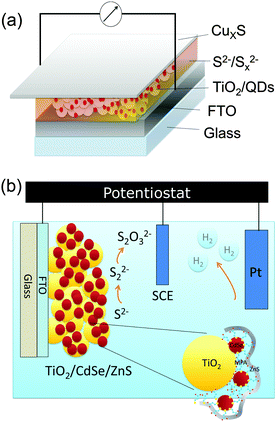
Fig. 1 shows the structures of the CdSe QD-sensitized electrodes for solar cells (Fig. 1(a)) and photocatalytic water splitting (Fig. 1(b)). The solar cells are composed of the mesoporous TiO2 sensitized with QDs, the polysulfide electrolyte, and a CuxS counter electrode. The photocatalytic water splitting device is composed of a QD sensitized mesoporous TiO2 photoelectrode (details in Fig. 1(b)), the electrolyte, a saturated calomel electrode (SCE) as reference, and a Pt coil as a counter electrode. In both devices ZnS is deposited on top of the QDs (Fig. 1(b)).The electrochemical reactions for both the water splitting and the solar cell devices are reported in the ESI.† The main difference between the two device structures is the electrolyte. The polysulfide electrolyte (Na2S/S) is used for QDSSCs and the sacrificial electrolyte (Na2S/Na2SO3) is used for the photoelectrochemical device.
The J–V characteristics and the EQE of the CdSe QD-sensitized solar cells with different number of ZnS layers are shown in Fig. 2(a) and (b), respectively. The CdSe QD sensitized electrodes with 5L ZnS coating on top made using the SILAR procedure show 1.6 times higher photocurrent and 6.3% higher photovoltage than the samples without ZnS coating. The energy conversion efficiency enhanced from 1.21% to 1.93% (2L ZnS) and to 2.04% (5L ZnS) upon ZnS coating. All the device parameters, obtained as an averaged value of the fabricated devices are reported in Table 1.
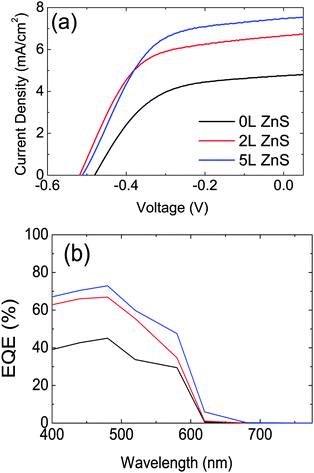 | ||
| Fig. 2 (a) J–V curves of CdSe QD-sensitized solar cells with 0, 2 and 5 layers of ZnS measured under 100 mW cm−2 at AM1.5. (b) The EQE of CdSe QD-sensitized solar cells as in panel (a). | ||
| Sample | I sc (mA cm−2) | V oc (V) | FF | Efficiency (%) |
|---|---|---|---|---|
| 0L ZnS | 4.81(0.36) | −0.48(0.01) | 0.53(0.01) | 1.21(0.15) |
| 2L ZnS | 6.65(0.04) | −0.52(0.01) | 0.56(0.02) | 1.93(0.11) |
| 5L ZnS | 7.52(0.44) | −0.51(0.01) | 0.53(0.02) | 2.04(0.15) |
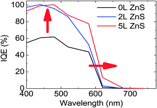
From the EQE data and the reflection and transmission measurements performed on the devices (Fig. S3 of the ESI†) we derived the internal quantum efficiency (IQE) of our solar cells (Fig. 3). Fig. 3 shows that 2L ZnS coating is enough to increase the IQE from 61% to 100% at 440 nm. Nevertheless, the highest power conversion efficiency of the devices is obtained with 5L ZnS, which seems to be due to the extended low energy tail of the EQE spectra of the sample. A similar red-shift is observed in the absorption measurements which are reported in Fig. S4 of the ESI.†
A similar effect upon ZnS deposition was reported by other authors24 and explained as being due to the larger delocalization of the carrier wave function in the presence of ZnS. We believe that the reason for this phenomenon should be found in interfacial effects occurring between CdSe and ZnS and in particular in the heterostructure formation between the two semiconductors, which will be discussed in detail later.
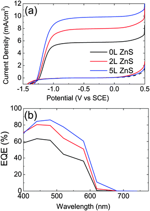
The same photoelectrodes are used to demonstrate photoelectrochemical hydrogen generation. The main difference with respect to the QDSSC is the electrolyte and the counter electrodes as shown in Fig. 1(b). The J–V characteristics and the EQE of the photocatalytic CdSe QD-sensitized electrodes for water splitting are shown in Fig. 4(a) and (b), respectively. The three electrode configuration is used to characterize the properties of the photoanodes. In this configuration the H2 generation rate is proportional to the current density. Similarly to what was shown by the QDSSC, the CdSe QD-sensitized electrodes with 2L and 5L ZnS coating show 1.38 and 1.7 times higher photocurrent at −0.5 V vs. SCE, respectively, compared to that without ZnS coating. Current density up to ∼10 mA cm−2 under −0.5 V vs. SCE is achieved for CdSe QD-sensitized electrodes with 5L ZnS coating. The EQE spectra (Fig. 4(b)) recorded at −0.5 V vs. SCE show significantly enhanced photocurrent from 63% to 84% at 480 nm wavelength, upon 5L ZnS deposition. Moreover, here also the onset of the EQE spectra shows, similarly to the solar cells, a broadening at around 620 nm. This broadening makes the photocurrent spectra resemble closely the absorption spectra of the electrodes shown in Fig. S3b (ESI†).
The stability of the photoelectrodes under continuous light illumination is shown in Fig. 5, demonstrating that the ZnS coating not only increases the efficiency of the devices but also the photostability. The photocurrent of the pristine CdSe photoanode decays 60% after 1 h continuous illumination under AM 1.5 at 1 sun light intensity; while for the same electrode with 2L and 5L of ZnS coating, the photocurrent decays 33% and 10%, respectively.
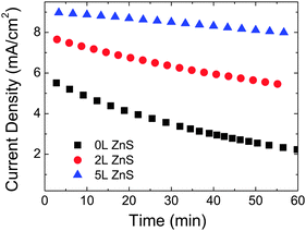 | ||
| Fig. 5 Time dependent current density of the CdSe QD-sensitized electrodes under continuous illumination with 100 mW cm−2 and a bias of −0.5 V vs. SCE. | ||
Many authors of the recent literature believe that ZnS coating acts as a barrier, which suppresses the recombination of electrons (in either TiO2 or CdSe) with the electrolyte; others reported that ZnS has the role of passivating defects at the quantum dot surface and preventing photocorrosion.24–28 To further investigate the working mechanism of ZnS coating in the colloidal quantum dot-sensitized electrodes using MPA as a crosslinker, steady-state and time-resolved photoluminescence are measured.
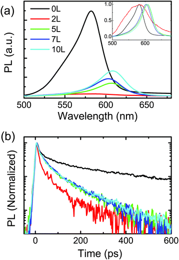
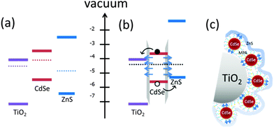
Fig. 6(a) shows the steady state PL spectra of the TiO2/CdSe electrode with different number of layers of ZnS. Upon deposition of 2L of ZnS, the photoluminescence signal is strongly quenched and becomes very broad (inset of Fig. 6(a)). The further deposition of ZnS layers on the same sample red-shifts the photoluminescence signal (peak from 581 nm to 607 nm) while the intensity partially recovers (Fig. 6(a)). Time-resolved photoluminescence measurements allow gaining a clearer picture of the physics at the interface between CdSe and ZnS. Fig. 6(b) shows the PL lifetimes of samples of TiO2/CdSe and TiO2/CdSe with 2, 5, 7 and 10 layers of ZnS on top. The lifetimes fitted with a bi-exponential function are ∼11 ps (τ1) and ∼150 ps (τ2) for the TiO2/CdSe, quenched to ∼8 ps (τ1) and ∼41 ps (τ2) for the TiO2/CdSe/ZnS (2L). With 5L of ZnS coating, the exciton lifetime increases to 12 ps (τ1) and 67 ps (τ2). The results of the fittings of the time-resolved PL are summarized in Table S2 (ESI†). It is worth noting that the measurements were performed in the absence of the electrolyte on a single sample, on top of which subsequent layers of ZnS were deposited. The faster decay of the photoluminescence suggests the formation of a type II heterojunction between the CdSe QDs and ZnS as shown in the schematic in Fig. 7(b) in which ZnS acts as a hole transporting layer. In addition, PL measurements in samples in which ZnS (2L) is deposited between TiO2 and CdSe were performed and compared with the reference samples composed of CdSe on TiO2 and with the samples with ZnS on top of CdSe. The measurements reported in Fig. S5 (ESI†) show an increase of the photoluminescence in the sample with ZnS between TiO2 and CdSe. These experiments provide further proof that CdSe/ZnS forms a type II heterostructure as shown in Fig. 7(b).
To explain how CdSe/ZnS can form a type II heterojunction (Fig. 7(b)) even if in bulk it forms a type I like heterojunction (Fig. 7(a)), we need to look carefully at the macroscopic view of our samples. Again, the QD-sensitized electrode is made by direct adsorption of CdSe QDs on mesoporous TiO2 followed by 3-mercaptopropionic acid ligand exchange. The thiols and carboxylic acid groups have a preference to bind with Cd and TiO2, respectively (Fig. 7(c)). 3-Mercaptopropionic acid is a molecular dipole on the CdSe QD surface, which shifts the relative band positions of CdSe and ZnS.29 It is supposed that the band energy is affected by both the Fermi levels of ZnS and CdSe as well as the dipoles of linkers.30 In general CdSe nanocrystals have n-type properties31 and ZnS has been reported having both n-type and p-type properties depending on the stoichiometric ratio of Zn and S.32 For the SILAR ZnS, the polarity is still not clear. As for the CdSe QDs with a thin layer (2L) of ZnS coating, the dipole dominates the band shifting, forming a type II heterojunction. However, with a relatively thick layer (5L) of ZnS coating, the Fermi level of ZnS causes the shifting of the band position, resulting in slightly enhanced light emission and exciton lifetimes. The red shift of PL (and of the absorption) peak with the increasing of the number of layers of ZnS coating is ascribed to the weakening of the quantum confinement in CdSe QDs towards the HOMO of the ZnS nanolayer. This is also demonstrated by the fact that the PL peak wavelength does not have variation until 5 layers of ZnS are deposited, which also correspond with the absorption measurements reported in Fig. S4 (ESI†). It is also interesting to note that the transition between 2 and 5 layers of ZnS correspond to the size of 1 nm and 2.4 nm, respectively, (determined by ellipsometry) in which the ZnS stops to be quantum confined (Bohr radius of ZnS is about 2.5 nm33).
The impact of ZnS coating is also investigated by impedance spectroscopy. The details of these experiments are reported in the ESI.† Briefly, the charge injection (separation) efficiency (Φinj) and the charge collection efficiency (ηc) can be derived according to eqn (1).
| IQE = Φinj·ηc | (1) |
Since the EQE measurement was done under weak light intensity (∼1 mW cm−2), Fig. S8c (ESI†) indicates that the charge collection efficiencies (ηc) of both devices under low light intensity are approaching 100%; therefore, Φinj can be estimated to have the same value as the IQE shown in Fig. 3. The main reason for the enhanced performance of the samples coated with ZnS is the increased charge injection efficiency. It is important to underline that the impedance spectroscopy, the optical measurements and the electrical measurements performed on the device point to the same interpretation of the role of ZnS in our device architecture, namely, TiO2/CdSe and the CdSe/ZnS heterojunctions drive the charge separation upon illumination.
4. Conclusions
We demonstrate highly efficient water splitting and sensitized solar cells by direct adsorption of colloidal CdSe QDs on mesoporous TiO2 followed by 3-mercaptopropionic acid ligand exchange. The QDSSC with 5L ZnS coating shows the best performance with the internal quantum efficiency approaching 100% and the energy conversion efficiency over 2%, while for photoelectrochemical H2 generation the current of ∼10 mA cm−2 under −0.5 V vs. SCE was achieved with the same electrode. Moreover, by correlating results from different experimental techniques we explain the role of the ZnS coating in the improved performance of the photo-electrode. Time-resolved photoluminescence indicates the formation of a type II heterojunction in CdSe/ZnS QDs, which together with the other type II heterojunctions formed with TiO2 allows a more efficient carrier separation. Carrier dynamic measurements performed with impedance spectroscopy indicate that the enhanced efficiency of the device with ZnS coating is caused by the higher carrier injection efficiency. Finally, the device results, the impedance spectroscopy, and the optical measurements all point to the same interpretation of the role of ZnS in our device architecture.Acknowledgements
Financial support from Foundation for Fundamental Research on Matter (FOM) for project “Towards bio-solar cells” (FOM15) and the Zernike Institute for Advanced Materials is acknowledged. The authors thank A. Kamp, R. Gooijaarts, and J. Baas for technical support. Finally, the authors would like to thank W. P. Liao, M. C. Chang and Dr S. Z. Bisri for discussions. L. H. Lai would like to thank Delta Electronics for their support.Notes and references
- A. Fujishima and K. Honda, Nature, 1972, 238, 37–38 CrossRef CAS.
- S. Hoang, S. Guo, N. T. Hahn, A. J. Bard and C. B. Mullins, Nano Lett., 2012, 12, 26–32 CrossRef CAS PubMed.
- M. Batzill, E. Morales and U. Diebold, Phys. Rev. Lett., 2006, 96, 026103 CrossRef.
- J. Luo, L. Ma, T. He, C. F. Ng, S. Wang, H. Sun and H. J. Fan, J. Phys. Chem. C, 2012, 116, 11956–11963 CAS.
- J. Luo, S. K. Karuturi, L. Liu, L. T. Su, A. I. Tok and H. J. Fan, Sci. Rep., 2012, 2, 451 Search PubMed.
- J. Hensel, G. Wang, Y. Li and J. Z. Zhang, Nano Lett., 2010, 10, 478–483 CrossRef CAS PubMed.
- R. Trevisan, P. Rodenas, V. Gonzalez-Pedro, C. Sima, R. S. Sanchez, E. M. Barea, I. Mora-Sero, F. Fabregat-Santiago and S. Gimenez, J. Phys. Chem. Lett., 2013, 4, 141–146 CrossRef CAS.
- J. W. Lee, D. Y. Son, T. K. Ahn, H. W. Shin, I. Y. Kim, S. J. Hwang, M. J. Ko, S. Sul, H. Han and N. G. Park, Sci. Rep., 2013, 3, 1050 Search PubMed.
- H. Kim, M. Seol, J. Lee and K. Yong, J. Phys. Chem. C, 2011, 115, 25429–25436 CAS.
- P. Rodenas, T. Song, P. Sudhagar, G. Marzari, H. Han, L. Badia-Bou, S. Gimenez, F. Fabregat-Santiago, I. Mora-Sero, J. Bisquert, U. Paik and Y. S. Kang, Adv. Energy Mater., 2013, 3, 176–182 CrossRef CAS.
- K. Shin, S. I. Seok, S. H. Im and J. H. Park, Chem. Commun., 2010, 46, 2385–2387 RSC.
- H. M. Chen, C. K. Chen, Y. C. Chang, C. W. Tsai, R. S. Liu, S. F. Hu, W. S. Chang and K. H. Chen, Angew. Chem., Int. Ed., 2010, 49, 5966–5969 CrossRef CAS PubMed.
- T. Nann, S. K. Ibrahim, P. M. Woi, S. Xu, J. Ziegler and C. J. Pickett, Angew. Chem., Int. Ed., 2010, 49, 1574–1577 CrossRef CAS PubMed.
- Z. Pan, K. Zhao, J. Wang, H. Zhang, Y. Feng and X. Zhong, ACS Nano, 2013, 7, 5215–5222 CrossRef CAS PubMed.
- Y.-L. Lee, C.-F. Chi and S.-Y. Liau, Chem. Mater., 2010, 22, 922–927 CrossRef CAS.
- G. Wang, X. Yang, F. Qian, J. Z. Zhang and Y. Li, Nano Lett., 2010, 10, 1088–1092 CrossRef CAS PubMed.
- M. Seol, J.-W. Jang, S. Cho, J. S. Lee and K. Yong, Chem. Mater., 2013, 25, 184–189 CrossRef CAS.
- L. H. Lai, L. Protesescu, M. V. Kovalenko and M. A. Loi, Phys. Chem. Chem. Phys., 2013, 16, 736–742 RSC.
- A. Salant, M. Shalom, I. Hod, A. Faust, A. Zaban and U. Banin, ACS Nano, 2010, 4, 5962–5968 CrossRef CAS PubMed.
- A. Salant, M. Shalom, Z. Tachan, S. Buhbut, A. Zaban and U. Banin, Nano Lett., 2012, 12, 2095–2100 CrossRef CAS PubMed.
- X. Y. Yu, J. Y. Liao, K. Q. Qiu, D. B. Kuang and C. Y. Su, ACS Nano, 2011, 5, 9494–9500 CrossRef CAS PubMed.
- K.-H. Lin, C.-Y. Chuang, Y.-Y. Lee, F.-C. Li, Y.-M. Chang, I. P. Liu, S.-C. Chou and Y.-L. Lee, J. Phys. Chem. C, 2012, 116, 1550–1555 CAS.
- O. Chen, X. Chen, Y. Yang, J. Lynch, H. Wu, J. Zhuang and Y. C. Cao, Angew. Chem., Int. Ed., 2008, 47, 8638–8641 CrossRef CAS PubMed.
- N. Guijarro, J. M. Campina, Q. Shen, T. Toyoda, T. Lana-Villarreal and R. Gomez, Phys. Chem. Chem. Phys., 2011, 13, 12024–12032 RSC.
- S.-m. Yang, C.-h. Huang, J. Zhai, Z.-s. Wang and L. Jiang, J. Mater. Chem., 2002, 12, 1459–1464 RSC.
- L. J. Diguna, Q. Shen, J. Kobayashi and T. Toyoda, Appl. Phys. Lett., 2007, 91, 023116 CrossRef PubMed.
- Y.-L. Lee and Y.-S. Lo, Adv. Funct. Mater., 2009, 19, 604–609 CrossRef.
- X. Wang, R. Liu, T. Wang, B. Wang, Y. Xu and H. Wang, ACS Appl. Mater. Interfaces, 2013, 5, 3312–3316 CAS.
- M. Soreni-Harari, N. Yaacobi-Gross, D. Steiner, A. Aharoni, U. Banin, O. Millo and N. Tessler, Nano Lett., 2008, 8, 678–684 CrossRef CAS PubMed.
- M. Shalom, S. Ruhle, I. Hod, S. Yahav and A. Zaban, J. Am. Chem. Soc., 2009, 131, 9876–9877 CrossRef CAS PubMed.
- J. S. Lee, M. V. Kovalenko, J. Huang, D. S. Chung and D. V. Talapin, Nat. Nanotechnol., 2011, 6, 348–352 CrossRef CAS PubMed.
- O. K. Echendu, A. R. Weerasinghe, D. G. Diso, F. Fauzi and I. M. Dharmadasa, J. Electron. Mater., 2013, 42, 692–700 CrossRef CAS.
- B. Bhattacharjee, D. Ganguli, K. IakoubovskIi, A. Stesmans and S. Chaudhuri, Bull. Mater. Sci., 2002, 25, 175–180 CrossRef CAS.
Footnotes |
| † Electronic supplementary information (ESI) available: Electrochemical reaction in photoanodes and cathodes, the effects of MPA ligand exchange for QDSSCs, absorbance, transmittance and reflectance spectra, photoluminescence of samples with different sequences of CdSe and ZnS on TiO2, electrochemical impedance spectroscopy (EIS) measurements, equivalent circuit fitting results of EIS and other parameters of cells, and TRPL fitting results. See DOI: 10.1039/c4cp00632a |
| ‡ These authors contributed equally to this work. |
| This journal is © the Owner Societies 2014 |

